

Wiedenmann Mega Twister Translation Of Original Operating Instructions

Translation of original
operating instructions
Leaf blower
Mega Twister
891.002
From machine ID no. :
Version :
August 2013
891 99 09
2
All information, illustrations and specifications in this manual are based on the latest information
available at the time of publication. We reserve the right to make changes at any time without notice.

3
|
All information, illustrations and specifications in this manual are based on the latest information
available at the time of publication. We reserve the right to make changes at any time without notice.

4
Introduction
PLEASE READ THESE OPERATION INSTRUCTIONS CAREFULLY in order to
familiarize yourself the correct method of operation and maintenance
and in order to avoid personal injuries or damage to the machine.
This manual and safety decals on your machine may also be available
in other languages (see your dealer to order).
THIS MANUAL SHOULD BE CONSIDERED a permanent part of your machine and
should remain with the machine when you sell it.
MEASUREMENTS in this manual are given in both metric and customary
U.S. unit equivalents. Only use suitable parts and screws. Metric
and inch fasteners may require a specific metric or inch wrench.
RIGHT - HAND AND LEFT - HAND sides refer to the direction of travel
the implement when going forward.
WRITE PRODUCT IDENTIFICATION NUMBERS (P.I.N.) in the Specification or
Identification Numbers section. Please ensure that all numbers are
correctly recorded. to help in tracing the machine should it be
stolen. Your dealer also requires this number when you order spare
parts. File the identification numbers in a secure place away from
the machine.
BEFORE DELIVERING THIS MACHINE, your dealer performed a pre-delivery
inspection to ensure best performance.
THIS MACHINE IS DESIGNED EXCLUSIVELY for commercial use and generating
wind with air without particles in the air flow in the maintenance
of grassy areas and parks (“INTENDED USE“).
Use in any other way is considered contrary to the intended use. The
manufacturer accepts no liability for damage or injury resulting
from this misuse, and these risks must be borne solely by the user.
Using the equipment in accordance with the specifications also
includes observance of the operating and maintenance conditions as
specified by the manufacturer.
PREDICTABLE MISUSE AND ABUSE. Persons and objects must not be
transported with the machine attached. Do NOT add material to the
blower through the suction screen.
THIS MACHINE SHOULD BE OPERATED, serviced and repaired only by persons
familiar with all its particular characteristics and acquainted with
the relevant safety requirements (accident prevention). The accident
prevention regulations, all other generally recognized regulations
on occupational health and safety, and the road traffic regulations
must be observed at all times. Any unauthorized modifications
carried out on this machine will relieve the manufacturer of all
liability for any resulting damage or injury.
NOTE THE INSTRUCTIONS
for driving on public roads:
"This machine is not suitable for travel on Highways or public
roads. It requires additional equipment for this (lighting kit,
warning signs for slow vehicles/SMV sign, reflectors). Please
contact us if you wish to purchase this optional equipment “
All information, illustrations and specifications in this manual are based on the latest information
available at the time of publication. We reserve the right to make changes at any time without notice.

5
C O N T E N T S Page
* * * * * * * * * * * * * * * * * * * * * * * * * * * * * * * * * * * * * * * * * * * * * * * * * * *
1.0. Safety............................................................. 6&15
1.1. Safety Decals.............................................. 11&13
1.2. Safety Equipment........................................... 14
1.3. The safety devices......................................... 15
2.0. Assembly........................................................... 16&22
2.1. General.................................................... 16
2.2. Mounting support wheels.................................... 16
2.3. Mounting roller unit....................................... 17
2.4. Hydraulic adjustment of the blowing nozzle................. 18
2.5. Hydraulic adjustment of the
blowing nozzle with control valve.......................... 19&20
2.6. Mounting electrical blowout nozzle adjustment............. 21
2.7. Mounting blowing nozzle.................................... 22
3.0. Transport.......................................................... 23&26
4.1. General.................................................... 23
4.2. Transporting the Mega Twister.............................. 24&25
4.3. Transportation with three-point attachment................. 26
4.0. Connecting to the tractor.......................................... 27&30
4.1. General.................................................... 27
4.2. Installing on the tractor.................................. 28
4.3. Adapting PTO Shaft......................................... 29
4.4. Supports................................................... 29
4.5. Unscrewing the running gear safety device.................. 29
4.6. Hydraulic connections...................................... 30
5.0. Disconnecting from the tractor..................................... 31&32
5.1. General.................................................... 31
5.2. Removing from tractor...................................... 31
5.3. Disconnecting hydraulic lines.............................. 32
5.4. Disconnecting drive shaft.................................. 32
5.5. Locking support wheels..................................... 32
6.0. Before Using....................................................... 33&35
6.1. General.................................................... 33
6.2. Drive speed and direction of rotation...................... 31
6.3. Top connecting rod position for working.................... 31
6.4. Swiveling the blower housing............................... 35
6.5. Adjusting the blowing nozzle............................... 35
7.0. Operation.......................................................... 36&37
7.1. General.................................................... 36
7.2. Switching on............................................... 36
7.3. Blower wheel............................................... 36
7.4. Danger zone................................................ 37
7.5. Work / Transport........................................... 37
8.0. Maintenance........................................................ 38&49
8.1. General.................................................... 38
8.2. Maintenance intervals...................................... 39
8.3. Lubrication points......................................... 40&41
8.4. Changing the gear oil...................................... 42
8.5. Cleaning................................................... 43
8.6. Hydraulics system.......................................... 43
8.7. Hydraulic connection diagram............................... 44&45
8.8. V – belt................................................... 46
8.9. Tire pressure.............................................. 47
8.10. Dismounting / Disposal..................................... 48
8.11. Unauthorized moddification and spare part manufacturing.... 49
9.0. Scope of delivery / Optional equipment............................. 50651
9.1. Series equipment........................................... 50
9.2. Accessories................................................ 51
10.0. Specification...................................................... 52&57
10.1. Dimensions, weights and other specifications.............. 52&55
10.2. Metric bolt and cap screw torque values................... 56
10.3. Serial Number............................................. 57
All information, illustrations and specifications in this manual are based on the latest information
available at the time of publication. We reserve the right to make changes at any time without notice.

6
Recognize safety information
This is the safety-alert
symbol. When you see this
symbol on your machine or
in this manual, be alert
to the potential for
personal injury.
Follow recommended
precautions and safe
operating practices.
1.0. Safety
Follow safety instuctions
Carefully read all safety
messages in this manual and on
your machine safety signs. Keep
safety signs in good condition.
Replace missing or damaged
safety signs. Be sure new
equipment components and repair
parts include the current
safety signs. Replacement
safety signs are available from
your dealer.
Learn how to operate the
machine and to use controls
properly. Do not let anyone
operate without instruction.
Keep your machine in proper
working condition. Unauthorized
modifications to the machine
may impair the fuction and/or
safety and affect machine life.
If you do not understand any
part of this manual and need
assistance, contact your
dealer.
All information, illustrations and specifications in this manual are based on the latest information
available at the time of publication. We reserve the right to make changes at any time without notice.
7
Observe road traffic regulations
Always observe local road
traffic regulations when using
public roads.
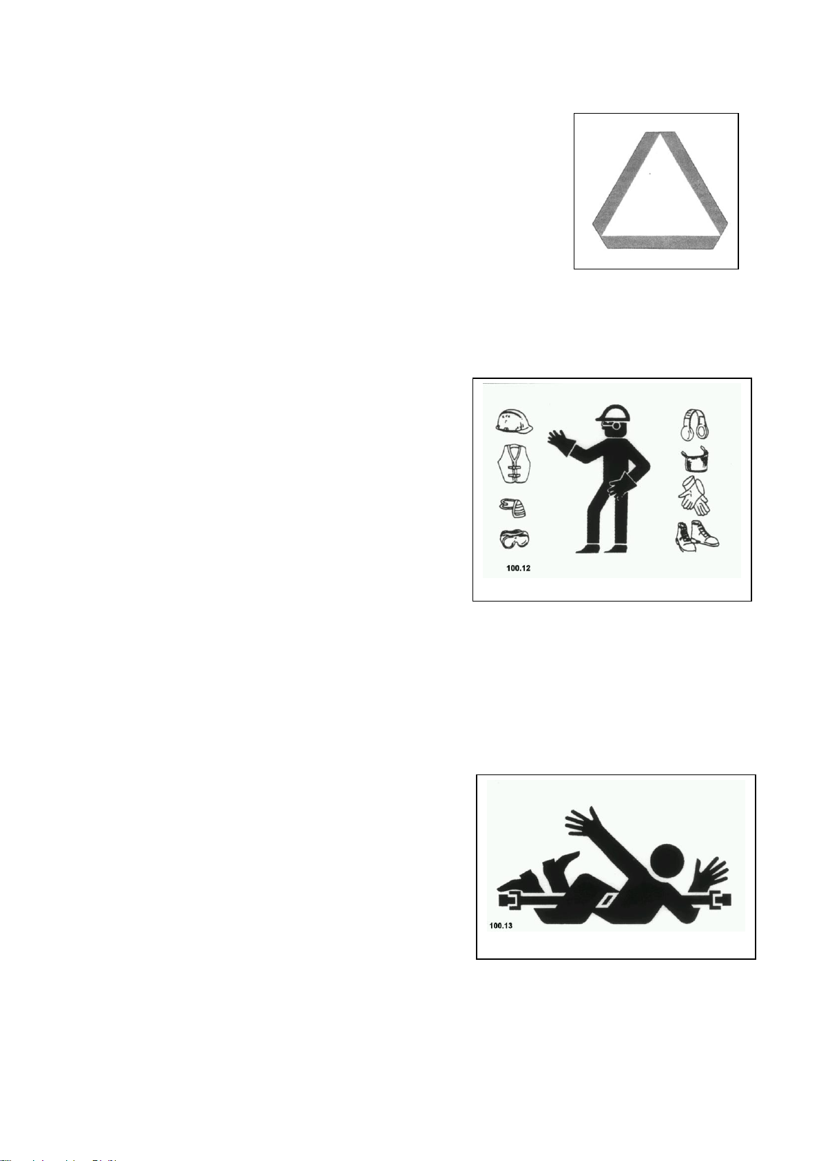
Wear protective clothing
Wear close fitting clothing and
safety equipment appropriate to
the job.
Prolonged exposure to loud
noise can cause impairment or
loss of hearing.
Wear a suitable hearing
protective device such as
earplugs to protect against
objectionable or uncomfortably
loud noises.
Operating equipment safety
requires the full attention of
the operator. Do not wear radio
or music headphones while
operating machine.
1.0. Safety
Stay clear of rotating drivelines
Entanglement in rotating
driveline can cause serious
injury or death.
Keep tractor master shield and
driveline shields in place at
all times. Make sure rotating
shields turn freely.
Wear close fitting clothing.
Stop the engine and be sure PTO
driveline is stopped before
making adjustments,
connections, or cleaning out
PTO driven equipment.
All information, illustrations and specifications in this manual are based on the latest information
available at the time of publication. We reserve the right to make changes at any time without notice.
8
Guard and shields
Keep guards and shields in
place all the times. Ensure
that they are in good condition
and installed correctly.
Always disengage the driveline,
turn off engine and remove key
before removing any guards or
shields.
Keep hands, feet and clothing
away from moving parts.
1.0. Safety
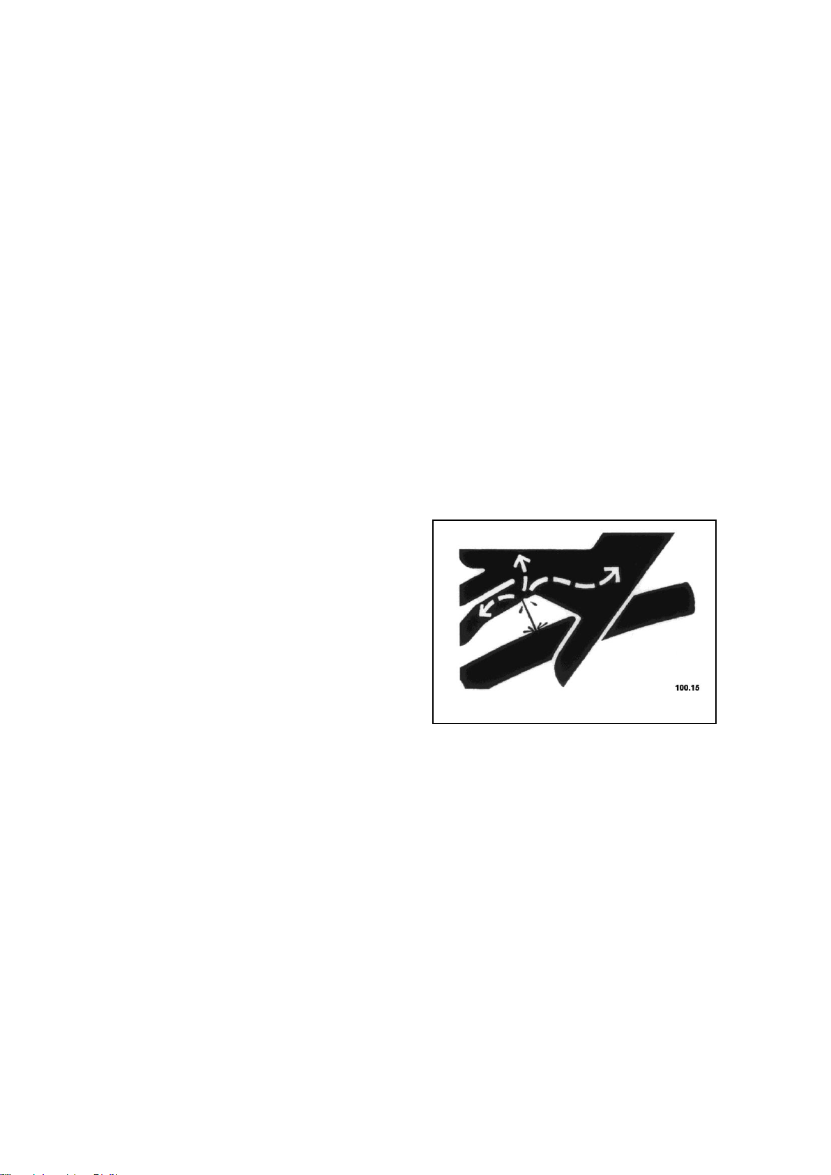
Avoid high - pressure fluids
Escaping fluid under pressure
can penetrate the skin causing
serious injury.
Avoid the hazard by relieving
pressure before disconnecting
hydraulic or other lines.
Tighten all connections before
applying pressure.
Search for leaks with a piece
of cardboard. Protect hands and
body from high pressure fluids.
If an accident occurs, see a
doctor immediately. Any fluid
injected into the skin must be
surgically removed within a few
hours or gangrene may result.
Doctors unfamiliar with this
type of injury should reference
a knowledgeable medical source.
All information, illustrations and specifications in this manual are based on the latest information
available at the time of publication. We reserve the right to make changes at any time without notice.
9
Use safety lights and devices
Prevent collisions between
other road users, slow moving
tractors with attachments or
towed equipment, and selfpropelled machines on public
roads. Frequently check for
traffic from the rear,
especially in turns, and use
hand signals or turn signal
lights. Use headlights,
flashing warning lights, and
turn signals day and night.
Follow local regulations for
equipment lighting and marking.
Keep lighting and marking
visible and in good working
order. Replace or repair
lighting and marking that has
been damaged or lost. An
implement safety lighting kit
is available from your dealer.
1.0. Safety
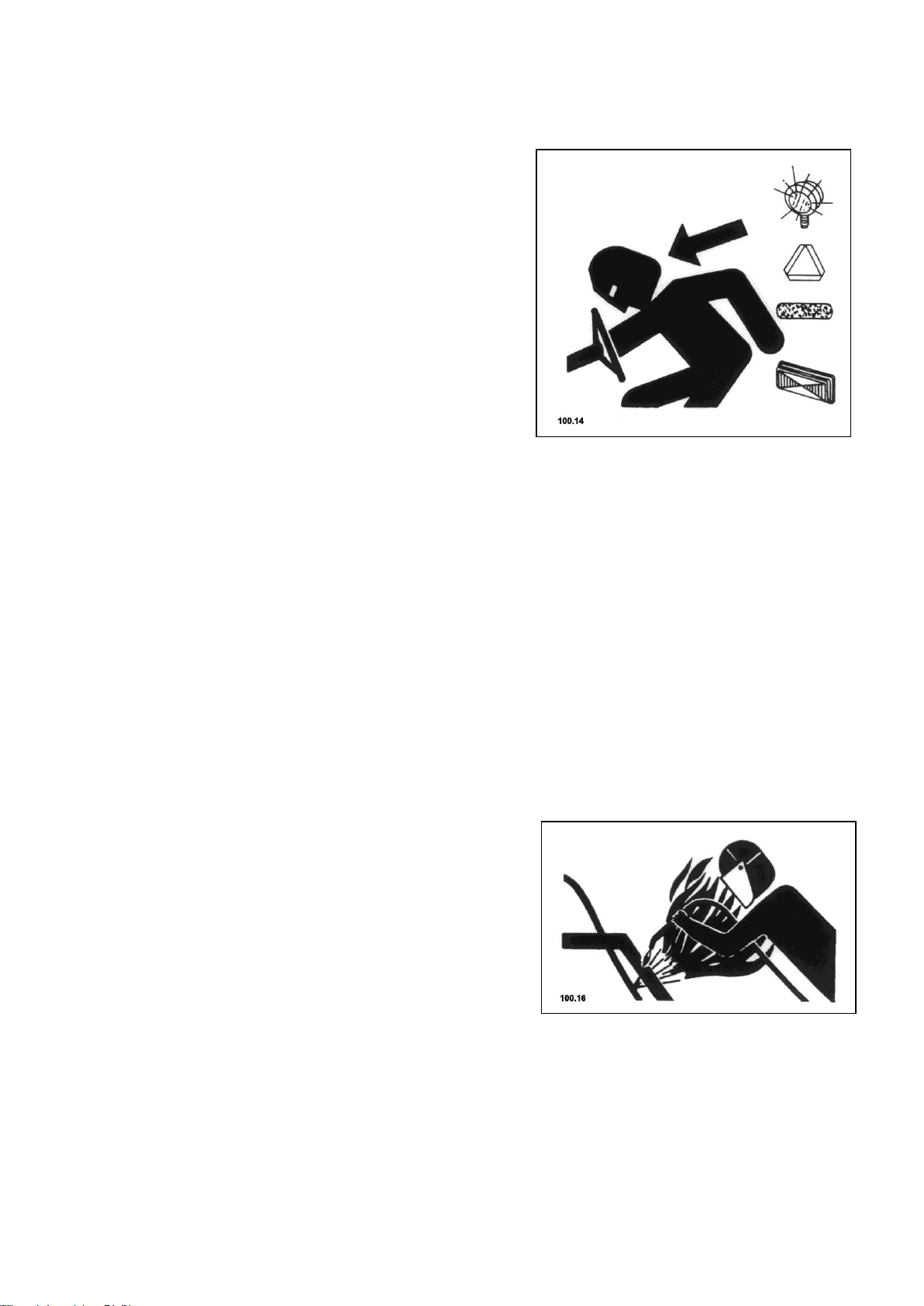
Avoid heating near pressurized fluid lines
Flammable spray can be
generated by heating near
pressurized fluid lines,
resulting in severe burns to
yourself and bystanders.
Do not heat by welding,
soldering, using a torch near
pressurized fluid lines or
other flammable materials.
Pressurized lines can be
accidentally cut when heat goes
beyond the immediate flame
area.
All information, illustrations and specifications in this manual are based on the latest information
available at the time of publication. We reserve the right to make changes at any time without notice.

10
1.0. Safety
Avoid heating near pressurized fluid lines
Welding must be conducted only
by persons with appropriate
qualifications.
Avoid potentially toxic fumes
and dust.
Hazardous fumes can be
generated when paint is heated
by welding, soldering, or using
a torch.
Do all work outside or in a
well ventilated area. Dispose
of paint and solvent properly.
Remove paint before welding or
heating:
If you sand paint, avoid
breathing the dust. Wear an
approved respirator.
If you use solvent or paint
stipper, clean with soap and
water before welding. Remove
solvent or paint stripper
containers and other flammable
material from area. Allow
fumes to disperse at least 15
minutes before welding or
heating.
All information, illustrations and specifications in this manual are based on the latest information
available at the time of publication. We reserve the right to make changes at any time without notice.
11
1.1. SAFETY DECALS
891.01
891.02
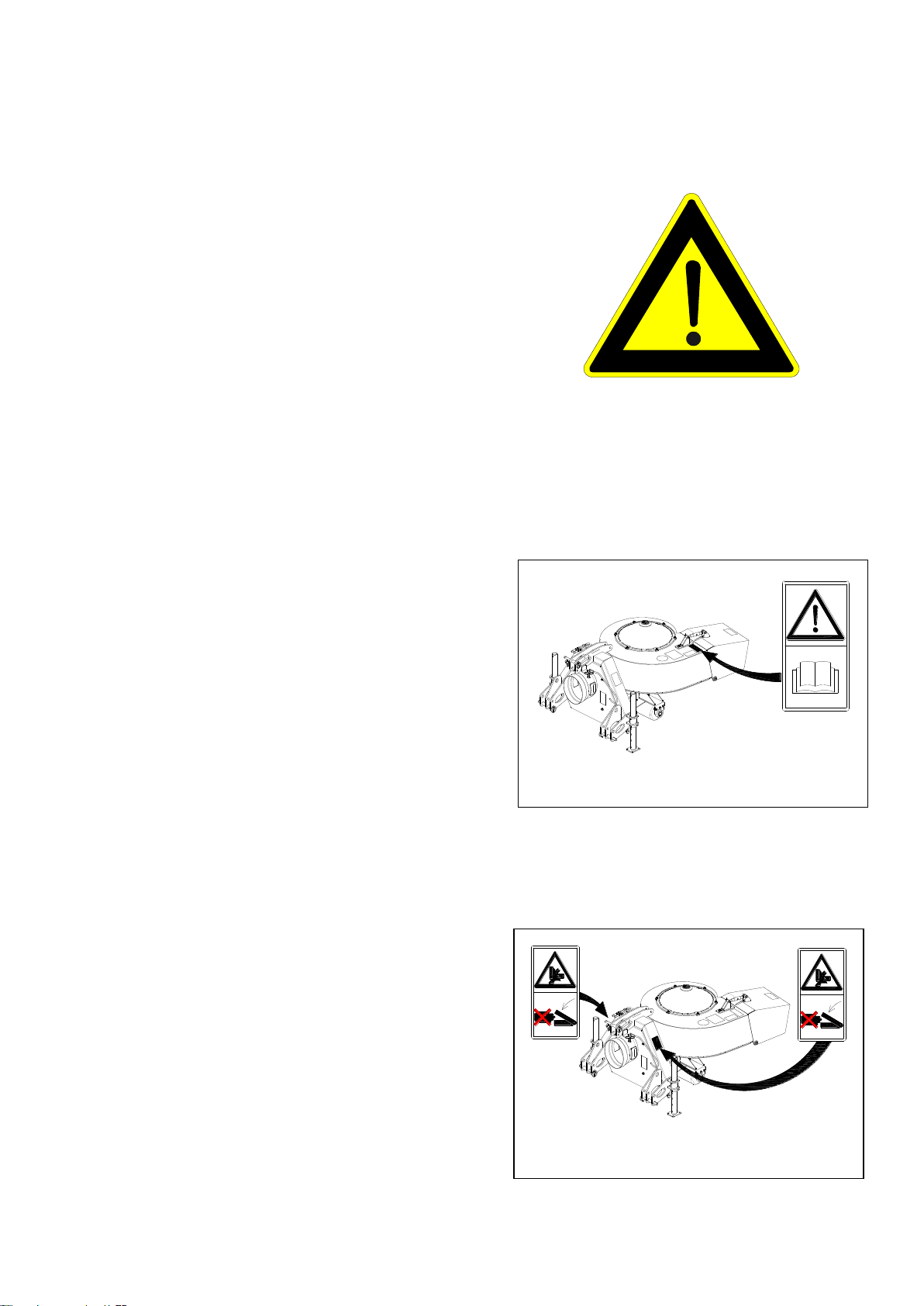
Pictorial safety signs
At several important places on this
machine safety signs are affixed in
order to signify potential danger.
The hazard is identified by a
exclamation point in a warning
triangle. An adjacent pictorial
provides information on how to
avoid personal injury. These safety
signs, their placement on the
machine and a brief explanatory
text are shown below.
1.0. Safety
Operator’s manual
This operator’s manual contains
all important information
necessary for safe machine
operation.
Carefully observe all safety
rules to avoid accidents.
Swiveling range
Due to danger of crushing,
never put your hands in danger
areas as long as components are
still moving.
All information, illustrations and specifications in this manual are based on the latest information
available at the time of publication. We reserve the right to make changes at any time without notice.
12
1.1. SAFETY DECALS
891.03
891.04
891.05
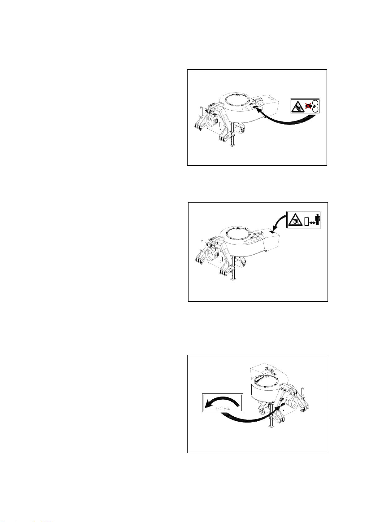
Blower
Never put your hands inside the
blower while the engine is
running.
Blowing nozzle
When operating ensure that
sufficient distance is left as
there is a risk of injury from
thrown or flying objects.
1.0. Safety
Power take-off shaft direction of
rotation and speed
It is essential that the
direction of rotation of the
power take-off shaft be
observed. Please check during
commissioning. The specified
speed must not be exceeded
because this would cause
serious damage to the blower.
All information, illustrations and specifications in this manual are based on the latest information
available at the time of publication. We reserve the right to make changes at any time without notice.
13
1.1. SAFETY DECALS
891.06
891.07
891.08
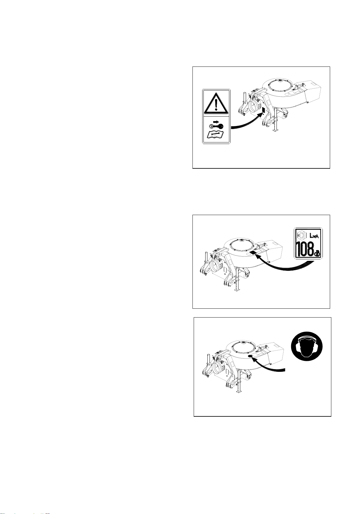
Service
Before performing service or
repair work, turn off engine
and remove key.
Noise level
This decal indicates the value
determined in accordance with
Article 13 of Directive
2000/14/EC
When used for several hours, we
recommend the use of ear
protectors.
1.0. Safety
All information, illustrations and specifications in this manual are based on the latest information
available at the time of publication. We reserve the right to make changes at any time without notice.

14
1.2. Safety instructions
1. Besides the information in
these operating
instructions, please also
observe generally
applicable safety and
accident-prevention
standards!
2. Familiarize yourself with
all equipment and operating
elements and their
functions before starting
work. Ensure that all
protective equipment has
been properly installed.
It is too late to do this
when you have started work!
3. In the working area, the
user is responsible for the
safety of other persons.
4. All persons must be out of
the danger area before
starting.
5. If there are persons in the
danger zone of the machine,
switch off the drives
immediately.
6. During operation on public
highways, the relevant
traffic regulations must be
observed.
7. Before moving off, ensure
that the immediate area of
the machine is clear e.g.
no children nearby. Ensure
that your visibility is not
impaired!
1.0. Safety
9. Mount the appliance only
when the motor and the
power take-off shaft have
been switched-off.
10. Use only cardan shafts
prescribed for the machine
which is being mounted.
11. Always ensure there is
sufficient axle load; the
steering capability of the
vehicle must be
maintained.
12. The driving and
operational
characteristics of the
tractor may be influenced
by the attachment of the
machine. Always adapt your
driving style to match the
terrain and ground
conditions. Special care
should be taken when
working and turning on a
slope.
13. Switch off the machine and
the tractor engine when
performing any maintenance
work. All protective
devices must be mounted
before operating the
blower.
8. Keep all persons clear of
the danger zone of the
machine!
All information, illustrations and specifications in this manual are based on the latest information
available at the time of publication. We reserve the right to make changes at any time without notice.
15
1.0. Safety
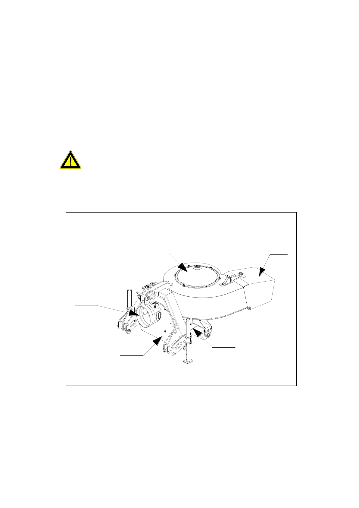
A = Covers, only removable
with tools.
C = Grid plates, only
removable with tools.
B = Protection for p.t.o.
shaft connection can only
be released using a tool.
D = Blower funnel, only
removable with tools.
C
A
B
A
891.09
D
1.3. The safety devices
GENERAL REQUIREMENTS FOR SAFETY IDENTIFICATION
Safety identification with the following safety actions or similar
notification should be attached to the machine. Where possible,
the label should be visible from all work positions.
a) Read the Operating Instructions.
b) Never operate the machine without protection, shields and
functioning safety devices.
c) Never operate the machine if persons, especially children, are
nearby.
d) Never allow the machine to be operated by persons who have not
received instruction.
CAUTION, DANGER! Never operate the Mega Twister without
safety devices. Otherwise you would be exposing yourself
and those around you to extreme danger.
Very serious injuries can be caused by moving parts.
The locations of the safety devices on your machine
All information, illustrations and specifications in this manual are based on the latest information
available at the time of publication. We reserve the right to make changes at any time without notice.
16
2.1. General
The machine must be attached
to the tractor for all work.
Lift the attached machine
with the rear hydraulics
until the stand can be
inserted into one of the top
holes.
- RISK OF INJURY!
For this work, please use your
personal protective equipment
(PSA) such as: gloves,
goggles, ear protectors.
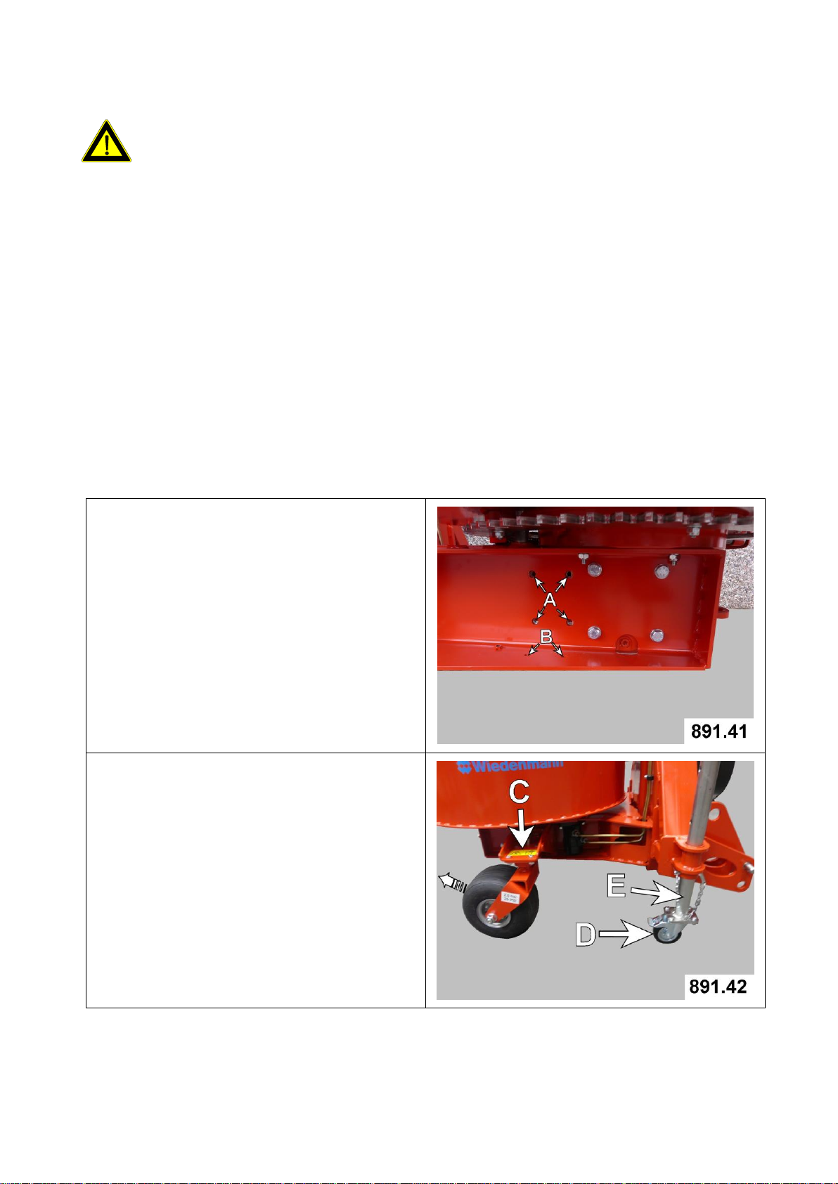
The mounting points for the two
support wheel holders are:
4 threaded holes (A)
2 holes (B)
Figure 891.42 shows the right
support wheel (C) mounted and
the locked wheel is rotated to
the back.
The included support roller with
brake (D) must be fastened to
the bottom of the stand (E).
Attention:
2.2. Mounting support wheels
2.0. Assembly
All information, illustrations and specifications in this manual are based on the latest information
available at the time of publication. We reserve the right to make changes at any time without notice.
17
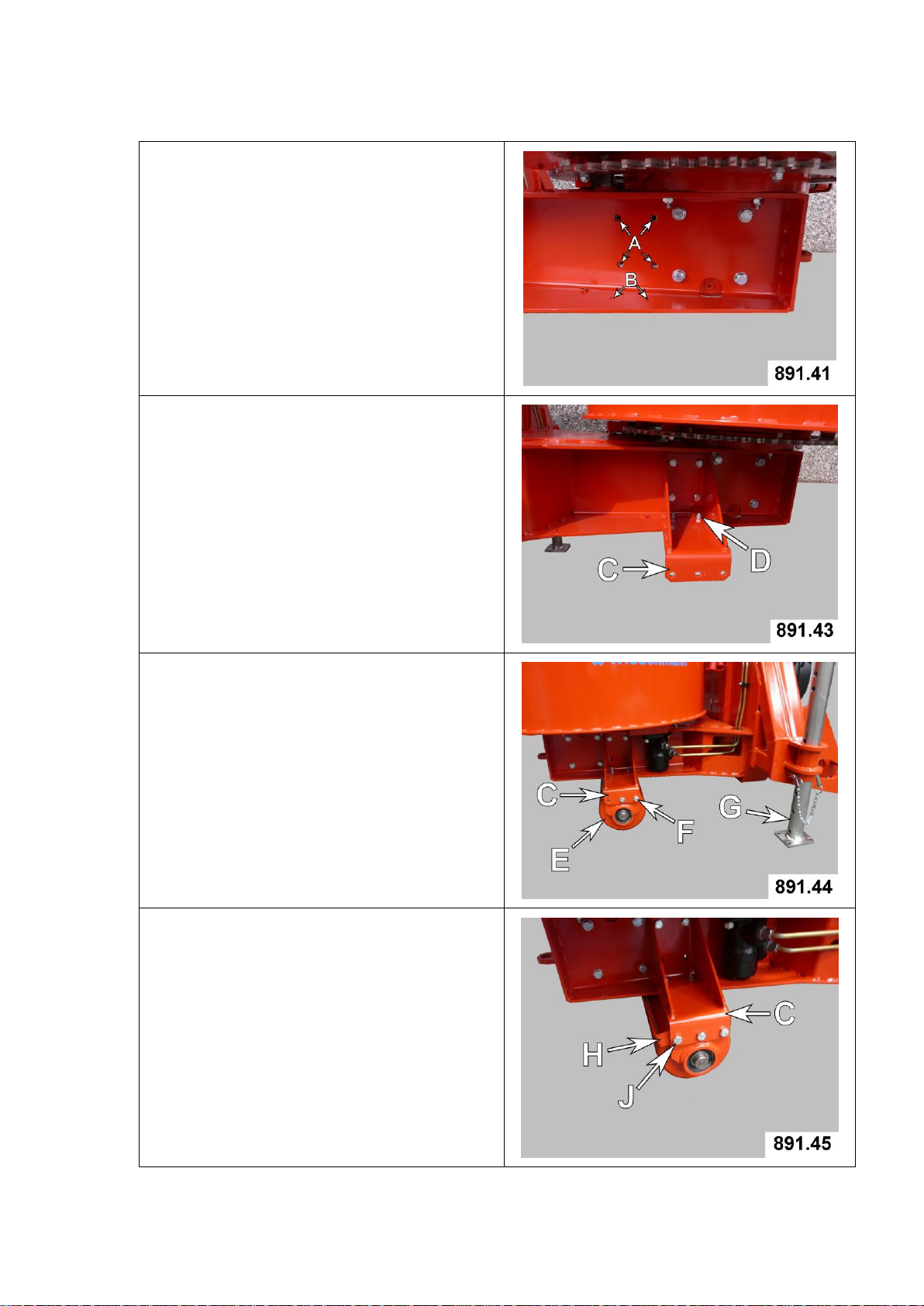
2.3. Mounting roller unit
The mounting points for the
roller unit are:
4 threaded holes (A)
2 holes (B)
Mount support (C) on both
sides..
The hexagonal bolts (D) must be
inserted from below.
The roller (E) with the
bearings must be fastened on
both sides to the support (C)
at the front holes with two
hexagonal bolts each (F).
Support rollers are NOT mounted
on the stand (G) with the
roller unit version.
The wiper bracket (H) is
fastened to the support (C)
with the last hexagon bolts (J)
and fixed to the roller with a
small clearance.
2.0. Assembly
All information, illustrations and specifications in this manual are based on the latest information
available at the time of publication. We reserve the right to make changes at any time without notice.
18
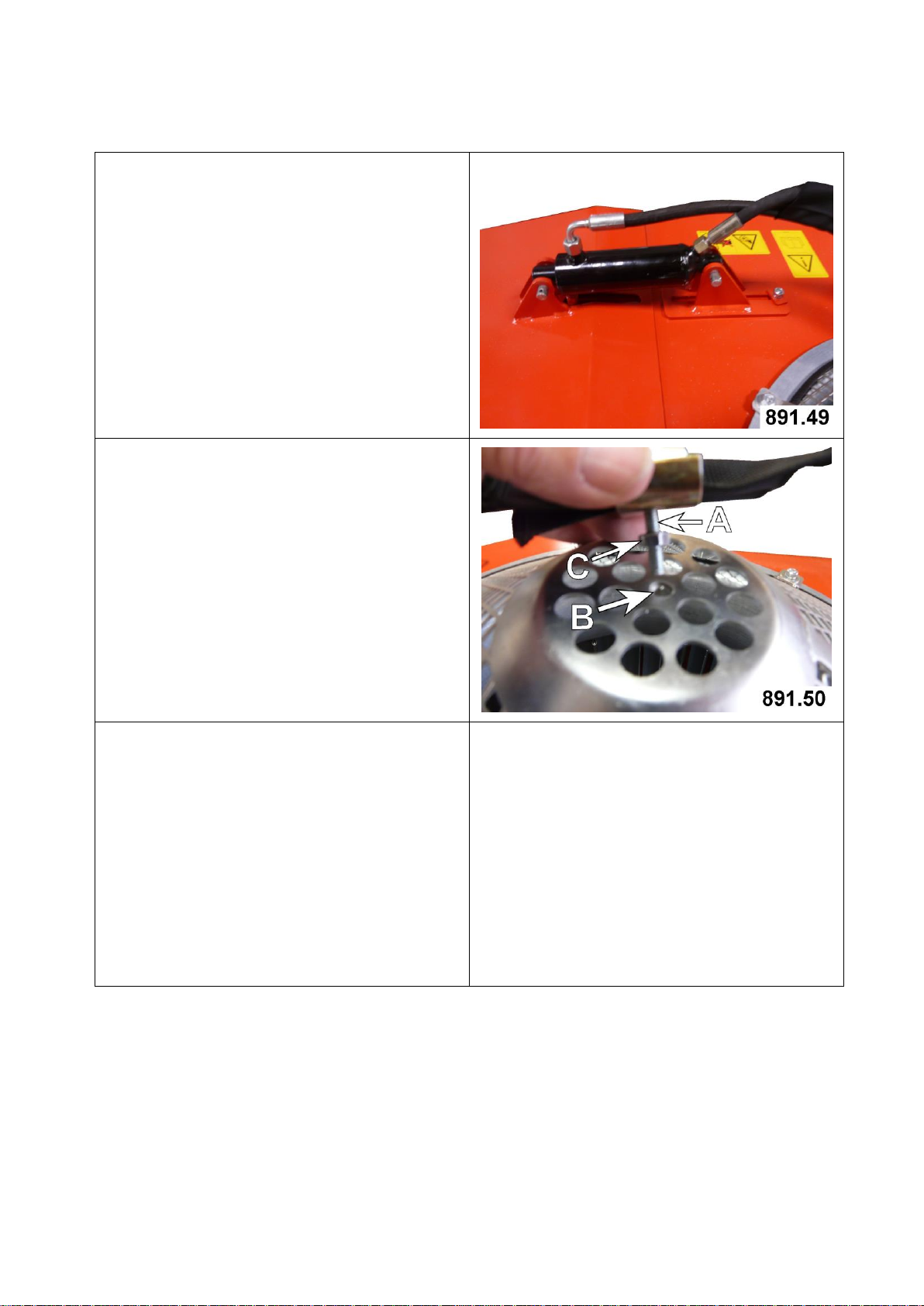
2.0. Assembly
Carried out via an additional
hydraulic cylinder (optional).
Mount the hydraulic cylinder
instead of the mechanical
adjustment.
Secure pin with linch pin.
Screw hexagon bolt (A) into the
thread on the screen (B).
Screw the hexagon nut (C) down
to fix the bolt.
The hydraulic hoses fixed by the
two fastening clips must be able
to move easily.
Take the swiveling of the blower
housing into account when fixing
the hydraulic hoses.
2.4. Hydraulic adjustment of the blowing nozzle
All information, illustrations and specifications in this manual are based on the latest information
available at the time of publication. We reserve the right to make changes at any time without notice.
 Loading...