

Wiedenmann Combi Clean 2350 Original Operating Instructions

Wiedenmann
Translation of original
Operating
Instructions
Sweeper
Combi Clean 2350
2350.002
Stand : August 2005
2350 99 01
Wiedenmann GmbH - D 89192 Rammingen
Tel. No.: +49 7345 / 953-02 Fax No.: +49 7345 / 953 233

EC-Declaration of Conformity
We
Wiedenmann GmbH
Am Bahnhof
89192 Rammingen
declare under our sole responsibility, that the product
Sweeper Combi Clean
Typ 2352 / 2353 / 2354
to which this declaration relates corresponds to the relevant basic safety and
health requirements of the Directive 98/37/EG.
Rammingen, the 27. July 2004 Peter Rischar
Technical Service
(Place and date of issue) (Name, function and signature
of authorised person)
NOTE: The conformity statement is no longer valid if changes are made to the
equipment that have not been agreed with the manufacturer.
2
All information, illustrations and technical specifications in this publication correspond to the latest version as per the time of
publishing. Constructions and designs are subject to modifications without prior notice.

Introduction
READ THIS MANUAL carefully to learn how to operate and service
your machine correctly Failure to do could result in personal
injury or equipment damage. This manual and safety signs on your
machine may also be avaiable in other languages (see yourdealer
to order).
THIS MANUAL SHOULD BE CONSIDERED a permanent part of your machine
and should remain with the machine when you sell it.
MEASUREMENTS in this manual are given in both metric and customary
U.S. unit equivalents. Use only correct repacement parts and
fasteners. Metric and inch fasteners may require a specific
metric or inch wrench.
RIGHT - HAND AND LEFT - HAND sides are determined by facing the
direction the implement will travel when going forward.
WRITE PRODUCT IDENTIFICATION NUMBERS (P.I.N.) in the Specification
or Identification Numbers section. Accurately record all the
numbers to help in tracing the machine should it be stolen. Your
dealer also needs these numbers when you order parts. File the
identification numbers in a secure place off the machine.
BEFORE DELIVERING THIS MACHINE, your dealer performed a predlivery
inspection to ensure best performance.
THIS MACHINE IS DESIGNED EXCLUSIVELY for regular employment in the
maintenance of roads and grassy areas (“SPECIFIED USE“).
Use in any other way is considered as contrary to the intended
use. The manufacturer accepts no liability for damage or injury
resulting from this misuse, and these risks must be borne solely
by the user. Compliance with and strict adherence to the
conditions of operation, service and repair as specified by the
manufacturer also constitute essential elements for the intended
use.
THIS MACHINE SHOULD BE OPERATED, serviced and repaired only by
persons familiar with all ist particular characteristics and
acquainted with the relevant safety rules (accident prevention)
The accident prevention regulation, all other generally
recognized regulations on safety and occupational medicine and
the road traffic regulations must be observed at all times.
Any arbitrary modifications carried out on this material
collection system will relieve the manufacturer of all liability
for any resulting damage or injury.
All information, illustrations and technical specifications in this publication correspond to the latest version as per the time of
publishing. Constructions and designs are subject to modifications without prior notice.
3

C O N T E N T S Page
* * * * * * * * * * * * * * * * * * * * * * * * * * * * * * * * * * * * * * * * * * * * * * * * * *
1.0. Safety Measure 5-9
1.1. Safety Label........................................................................................ 10-11
1.2. Safety Directions.................................................................................. 12
2.0. Connecting 13-17
2.1. General............................................................................................... 13
2.2. Installation with standard three-point linkage CAT.1……......................... 13
2.3.
2.4. Extension for standard three-point linkage and triangular coupling........... 15
2.5. Etting cylinder broom............................................................................ 15
2.6. Direction of rotation of cylinder broom.................................................... 16
2.7. Support leg.......................................................................................... 16
2.8. Connecting the hydraulics..................................................................... 16
2.9.
3.0. Disconnecting 18-19
3.1.
3.2. Support leg.......................................................................................... 18
3.3. Dismantling with standard three-point linkage cat.1................................. 19
3.4. Dismantling
Mounting Using the Coupling Triangle
Cardan shaft adjustment....................................................................... 17
General............................................................................................... 18
with Coupling Triangle
................................................ 14
...................................................... 19
4.0. Operating 20-21
4.1. General............................................................................................... 20
4.2. Installation of the side mounting............................................................ 20
4.3. Installation of dirt container................................................................... 21
4.4. Installing lateral broom............................................................................. 21
5.0. Operation 22-24
5.1. General............................................................................................... 22
5.2. Working with the sweeping machine...................................................... 22
5.3. Working speed..................................................................................... 23
5.4. V-belt drive.......................................................................................... 23
5.5. Changing speed of driving motor........................................................... 23
5.6.
5.7.
Switching off lateral broom drive............................................................ 24
Switching on lateral broom drive............................................................ 24
6.0. Maintenance 25-30
6.1.
6.2.
General............................................................................................... 25
Changing the cylinder broom................................................................. 25
6.3. Cleaning.............................................................................................. 26
6.4. Check and tension the drive V-belts....................................................... 26
6.5. Lubrication points................................................................................. 27+28
6.6. Hydraulic installation............................................................................. 29
6.7. Dismounting/Disposal........................................................................... 30
6.8. Modification......................................................................................... 30
7.0. Device combinations
7.1. Versions.............................................................................................. 31
8.0. Additional equipment
7.2. Accessories......................................................................................... 32
9.0. Technical specifications...................................................................................... 33-40
4
All information, illustrations and technical specifications in this publication correspond to the latest version as per the time of
publishing. Constructions and designs are subject to modifications without prior notice.
Recognize safety information
This is the safety-alert symbol.
When you see this symbol on your
machine or in this manual, be
alert to the potential for
personal injury.
Follow recommended precautions
and safe operating practices.
Follow safety instuctions
Carefully read all safety
messages in this manual and on
your machine safety sings. Keep
safety sings in good condition.
Replace missing or damaged safety
sings. Be sure new equipment
components and repair pqarts
include the curret safety sings.
Replacement safety sings are
available from your dealer.
1.0. Safety
Learn how to operate the machine
and to use controls properly. Do
not let anyone operate without
instruction.
Keep your machine in proper
working condition. Unauthorized
modifications to the machine may
impair the fuction and/or safety
and afect machine life.
If you do not understand any part
of this manual and need assistance,
contact your dealer.
All information, illustrations and technical specifications in this publication correspond to the latest version as per the time of
publishing. Constructions and designs are subject to modifications without prior notice.
5

Observe road traffic regulations
Always observe llocal road traffic
regulations when using public roads.
Wear protective clothing
Wear close fitting clothing and
safety equipment appropriate to
the job.
Prolonged exposure to loud noise
can cause impairment or loss of
hearing.
Wear a suitable hearing
protective device such as
earmuffs or earplugs to protect
against objectionable or
uncomfortable loud noises.
1.0. Safety
Operating equipment safety
requires the full attention of
the operator. Deo not wear radio
or music headphones while
operating machine.
Stay clear of rotating drivelines
Entanglement in rotating
driveline can cause serious
injury or death.
Keep tractor master shield and
driveline shields in place at
all times. Make sure rotating
shields turn freely.
Wear close fitting clothing.
Stop the engine and be sure PTO
driveline is stopped before
making adjustments,
connections, or cleaning out
PTO driven equipment.
6
All information, illustrations and technical specifications in this publication correspond to the latest version as per the time of
publishing. Constructions and designs are subject to modifications without prior notice.

Guard and shields
Keep guards and shields in
place all the times. Ensure
that they are in good condition
and installedcorrectly.
Always disengage the driveline,
shut off engine and remove key
before removing any guards or
shields.
Avoid high - pressure fluids
Escaping fluid under pressure
can penetrate the skin causing
serious injury.
Avoid the hazard by relieving
pressure before disconnecting
hydraulic or other lines.
Tighten all connections before
applying pressure.
1.0. Safety
Search for leaks with a piece
of cardboard. Protect hands and
body from high pressure fluids.
If an accident occurs, see a
doctor immediately. Any fluid
injected into the skin must be
surgically removed within a few
hours or gangrene may result.
Doctors unfamiliar with this
type of injury should reference
a knowledgeable medical source.
All information, illustrations and technical specifications in this publication correspond to the latest version as per the time of
publishing. Constructions and designs are subject to modifications without prior notice.
7
1.0. Safety
Keep hands, feet and clothing away
from moving parts.Use safety lights and devices
Prevent collisions between
other road users, slow moving
tractors with attachments or
towed equipment, and selfpropelled machines on public
roads. Frequently check for
traffic from the rear,
especially in turns, and use
hand signals or turn signal
lights.
Use headlights, flashing
warning lights, and turn
signals day and night. Follow
local regulations for equipment
lighting and marking. Keep
lighting and marking visible
and in good working order.
Replace or repair lighting and
marking that has been damaged
or lost. An implement safety
lighting kit is available from
your dealer.
Avoid heating near pressurized
fluid lines
Flammable spray can be
generated by heating near
pressurized fluid lines,
resulting in severe burns to
yourself and bystanders. Do not
heat by welding,
soldering,using a torch near
pressurized fluid lines or
other flammable materials.
Pressurized lines can be
accidentally cut when heat goes
beyond the immediate flamme
area.
8
All information, illustrations and technical specifications in this publication correspond to the latest version as per the time of
publishing. Constructions and designs are subject to modifications without prior notice.

Remove paint before welding or heating
Avoid potentially toxic fumes
and dust.
Hazardous fumes can be
generated when paint is heated
by welding, soldering, or using
a torch.
Do all work outside or in a
well ventilated area. Dispose
of paint and solvent properly.
Remove paint before welding or
heatingh:
• If you sand or grind paint,
avoid breathing the dust.
Wear an approved respirator.
• If you use solvent or paint
stipper with soap and water
before welding. Remove
solvent or paint stripper
containers and other
flammable material from area.
Allow fumes to disperse at
least 15 minutes before
welding or heating.
1.0. Safety
All information, illustrations and technical specifications in this publication correspond to the latest version as per the time of
publishing. Constructions and designs are subject to modifications without prior notice.
9
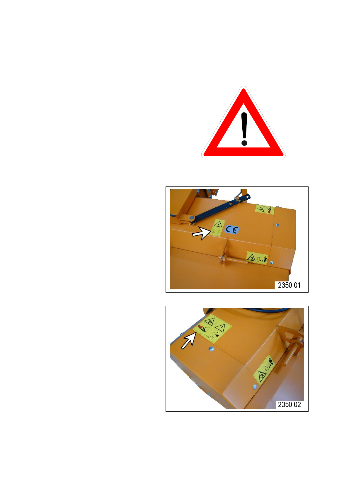
1.1. Safety Decals
Pictorial safety sings
At several important places
of this machine safety sings
are affixed intendent to
signify potenial danger. The
hazard is identified by a
pictorial in a warning
triangle. An adjacent
pictorial provides information
how to avoid personal injury.
These safety sings, their
placement on the nachine and
a brief explanatory text are
shown below.
Operator’ manual
This operator’s manual
containsall important
information necessary for
safe machine operation.
Carefully observe all
safety rules to avoid
accidents.
Protectors
Never reach into areas of
crushing hazard as long
as any parts may move.
1.0. Safety
10
All information, illustrations and technical specifications in this publication correspond to the latest version as per the time of
publishing. Constructions and designs are subject to modifications without prior notice.
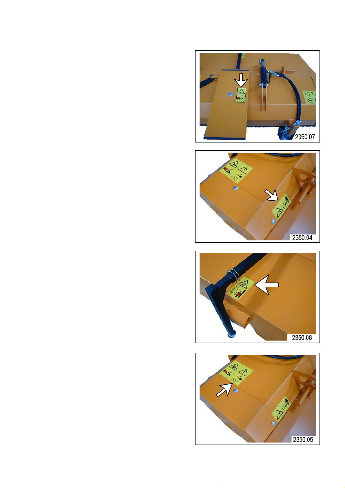
1.1. Safety Decals
Avoiding injury from rotating blade
When the engine is running,
keep a safe distance from
the mowing blades.
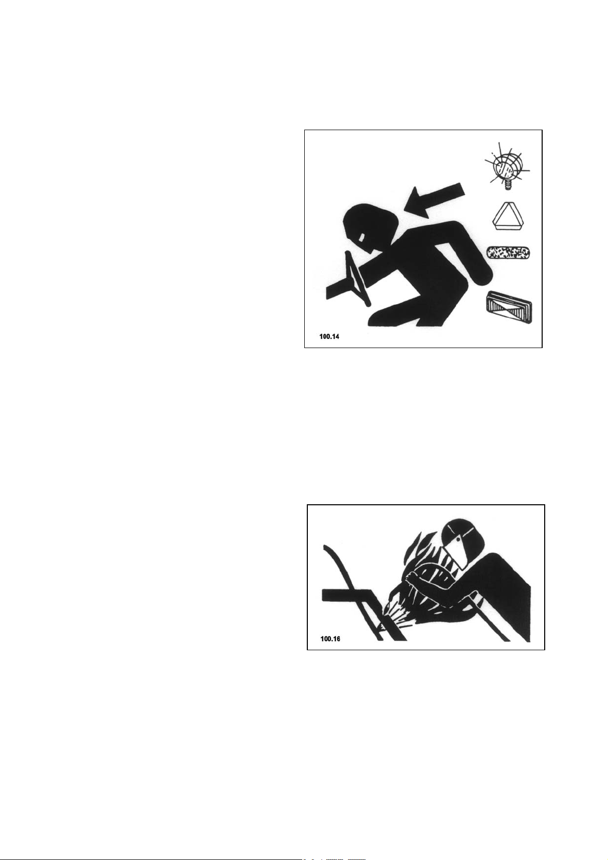
Tools
When operating ensure that
sufficient distance is left as
there is a risk of injury from
thrown or flying objects.
Container opening
When the tractor engine is
running, stay clear of the
swivel area of the container
Service
Before performing service
or repair work, turn off
engine and remove key.
1.0. Safety
All information, illustrations and technical specifications in this publication correspond to the latest version as per the time of
publishing. Constructions and designs are subject to modifications without prior notice.
11

1.2. Safety instructions
1.0. Safety
- Besides the information in
these operating
instructions, please also
observe generally applicable
safety and accidentprevention standards!
- Familiarise yourself with
all equipment and operating
elements and their functions
before starting work. Ensure
that all protective
equipment has been properly
installed. It is too late to
do this when you have
started work!
- During work operation, the
user is responsible for the
safety of third parties!
- During operation on public
highways, the relevant
traffic regulations must be
observed!
- Before moving off, ensure
that the immediate area of
the machine is clear e.g. no
children nearby. Ensure that
your visibility is not
impaired!
- When driving the machine
outside the work area, the
drive should be switched off
and the attachment placed in
transport position.
- In event of malfunctions
(vibrations) or if the
machine runs over a foreign
object, turn off the drive,
switch off the engine (remove
ignition key or spark-plug
connector) and examine the
machine, particularly the
equipment, for damage.
- Damaged equipment must be
replaced.
- When working on the tool,
precautions should be taken
to prevent injury (e.g.
gloves).
- The driving and operational
characteristics of the
tractor may be influenced by
the attachment of the
sweeper. Always adapt your
driving style to match the
terrain and ground
conditions.
- Keep all persons clear of
the danger zone of the
machine!
- Mount the appliance only
when the motor and the power
take-off shaft have been
switched-off.
- Use only cardan shafts
prescribed for the machine
which is being mounted.
12
All information, illustrations and technical specifications in this publication correspond to the latest version as per the time of
publishing. Constructions and designs are subject to modifications without prior notice.
- Before carrying out any
maintenance work, the machine
and the tractor engine must
be switched off.
All protective devices must
be mounted before initial
operation.
 Loading...