

WidTherm MPR 1000 Installation And Maintenance Instructions

MPR PLINTH
Radiator
Installation and Maintenance
Instructions
Model MPR 1000
Widney Leisure Ltd
Saxon Business Park,
Hanbury Road,
Stoke Prior, Bromsgrove,
Worcestershire, B60 4AD.
England.
Telephone: +44 (0)1527 577800
Fax: +44 (0)1527 577900
CONNECTION TO THE MAINS POWER SUPPLY
Electrical installation shall be carried out by a competent installer who is registered with the
National Inspection Council for Electrical Installation Contracting (NICEIC) in accordance with BS
7671:1992 (16th Edition IEE W iring Regulations) and any local authority byelaws.
This appliance must be earthed
IMPORTANT: IF IN DOUBT ALWAYS SEEK THE ADVICE OF A COMPETENT ELECTRICIAN.
The Symbol shown here and on the product indicates that the product is classed as Electrical or Electronic Equipment
and should not be disposed with other household or commercial waste at the end of its working life.
The Waste of Electrical an d Electronic
Equipment (WEEE) Directive (2002/96 /EC) has been put in place to recycle products using best available recovery and recycling
techniques to minimise the impact on the e nvironment, treat any hazardous substances and avoid the in creasing landfill.
Product disposal instructions for residential users
When you have no f urther use for it, please remove any batteries and dispose of them and the product as per your local authority's
recycling processes. For more information please con tact your local authority or the retailer where the product was purchased.
Product disposal instructions for business users
This product should not be mixed with oth er commercial waste for disposal.
105293 Issue D
Electrical installation
Connect the appliance only to single phase AC supply of the voltage specified on the
rating plate on the body of the appliance.
Before commencing electrical connection, servicing or maintenance of the unit ensure
that the supply circuit used has been disconnected.
Prior to making the electrical connections, the aperture in the furniture must be
prepared. See Figs 1 & 2.
A fused (3 amp) switched double pole isolator with a contact separation of at least
3mm in both poles should be provided adjacent to the unit. From the heater run the 3
core PVC insulated PVC sleeved 0.75 mm² cable to the isolator.
Do not cover or hang clothes, towels etc over or near the heater as this could
cause over heating and possible damage.
The heater should not be used imm ediately below a socket outlet.
Do not install this heater in the immediate vicinity of a bath, shower or swimming
pool.
If this heater is used with an external programmed controller, thermal control, timer
or any other device, which switches the heater on automatically; a separate isolation switch
must be linked into the installation for the safety of the installer or service engineer.
Do not allow an excess of cable between the appliance and the furniture as this
may be snagged or trapped when fitting the heater into the furniture cavity.
Introduction
The Mini Plinth Heater is designed for use on a normal wet two pipe pumped central
heating system.
It is specifically intended to replace radiators where space is limited or wall hung devices
are inappropriate.
The unit locates behind the kickboard of modern built in furniture thereby utilising
space, which would not normally be used.
It is floor mounted and attaches itself to the kickboard where a minimum height of
110mm is available.
Principal of operation:
MPR 100 0 Fa n assiste d ra di at or
. The water
radiator fitted to this appliance is known as a fan coil radiator. A fan coil radiator
works differently to a normal wall radiator in that less water is needed to generate
heat, thus improving efficiency. The MPR system has a fan, which blows air
across the heater matrix within the unit; the air enters the unit at room
temperature and exits at the temperature set by the water. Operation of the MPR
is automatic in that once the water reaches a temperature of 55°C or above the
fan will operate and heat will be blown through the ducts into the room. The
thermostat mounted on the front of the unit will modulate the fan according to the
temperature set. It is important to note that the fan will not operate until the water
temperature reaches 55°C.
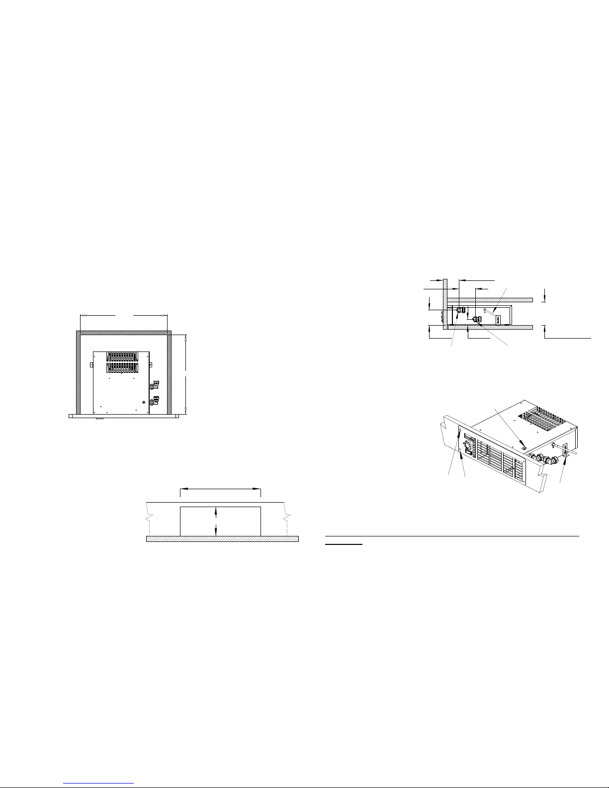
Front fix points
Air bleed
access point
Rear anchor
point
Fig 4
The fan will continue to run as long as the water is maintained at a temperature above
45ºC. When the boiler shuts down the fan blower will also shut down after a short delay.
The heater may be operated on sealed systems. This type is commonly found with modern
“combination” or system boiler installations where the maximum operating pressure is 3 bar
and maximum temperature of the water typically 85ºC
Installation:
The minimum space required to install the heater is as shown in fig 1& 2.
The unit must be fitted to an opening in the front face of the furniture 310mm x 95 mm.
Do not site the unit where it may be
dripped upon or where clothes or
coverings such as curtains can
obstruct the air slots at the front.
If the unit is fitted to the base of a
cupboard, a panel must be fitted
over the unit to seal it from ingress
of dust and any other objects.
Water connections:
The unit should be fitted
with isolating valves within
close proximity. This to
facilitate local draining for
any service work required.
In order to make the unit
removable from the front,
connecting pipe-work to the
heat exchanger tail pipes
should be compression type
and
NOT
solder capillary
type.
See Fig 1.
A removable access plate
fitted to the base of the
cupboard unit under which it
is fitted will ensure easy
access
Secure unit
Screw the front plate to the
face of the furniture using
screws provided and secure at
rear using anchor plates. (See fig
4.).
Commissioning:
The unit must be isolated
from electrical connection
whilst filling and purging
system of air.
When filling the heating system
the unit should self-vent but in
the case of an air lock, a bleed
screw is provided on the heater
connection tail pipe. (See fig 4).
Unscrewing the bleed nut ½ turn should allow any air in the heater coil to be expelled. Ensure all water
connections are sound and check the operation of the heater thermostats.
Turn the user adjustable thermostat at the front of the grill to the maximum position, then turn on the
central heating system and allow water to circulate through the coil.
ENSURE THAT ANY ISOLATING VALVES FITTED ARE SET TO THE OPEN
POSITION.
Turn on power to the unit from the isolator switch.
Once the water reaches a temperature of 55 C or above the fan will operate and will
continue to run until the air temperature in the room reaches the required comfort limit
set by the user operated thermostat
3
Minimum height
110 mm
75mm
72mm
76mm
29mm
Flow
Return
Fig 3
Mains electrical cable
400 min
350 min
Fig 1
310
95
Fig 2
Plinth cut away details.
 Loading...