

widos 6100 CNC 3.0 Working Instructions Translation
WIDOS Einsteinstr. 5 Phone +49 (0) 71 52 99 39 - 0
W. Dommer Söhne GmbH D-71254 Ditzingen-Heimerdingen Fax +49 (0) 71 52 99 39 - 40
Website: www.widos.de Email: info@widos.de
Working Instructions
Translation
Heating element butt welding machine
with CNC control unit
WIDOS 6100 CNC 3.0
Ku nststo ffschwei ßtec hni k
Keep for further use!
Headquarters: D-71254 Ditzingen-Heimerdingen Country court Stuttgart HRB 200973 Managing director: Jürgen Dommer

Product identification
Model: Heating element butt welding machine with
CNC control unit
Type: WIDOS 6100 CNC 3.0
Serial number, year of construction: see type lable
Customer entries
Inventory-no.:
Place of working:
Order of spare parts and after sales service:
Address of manufacturer WIDOS
W. Dommer Söhne GmbH
Einsteinstr. 5
Ku nststo ffschwei ßtec hni k
D -71254 Ditzingen-Heimerdingen
Phone: ++49 7152 / 99 39 - 0
Fax: ++49 7152 / 99 39 - 40
Address of the subsidiary companies
WIDOS
WIDOS GmbH W. Dommer Söhne AG
An der Wiesenmühle 15 St. Gallerstr. 93
D-09224 Grüna / Sachsen CH– 9201 Gossau
Phone: ++49 371 / 8 15 73 - 0 Phone: ++41 71 / 388 89 79
Fax: ++49 371 / 8 15 73 - 20 Fax: ++41 71 / 388 89 73
27.10.2011 Working Instructions WIDOS 6100 CNC 3.0 Page 2 of 76

Introduction
Ku nststo ffschwei ßtec hni k
Purpose of the document
These working instructions give you information about all important questions which refer to the
construction and the safe working of your machine.
Just as we are, you are obliged to engage in these working instructions, as well.
Not only to run your machine economically but also to avoid damages and injuries.
Should questions arise, contact our service team in the factory or in our subsidiary companies.
We will help you with pleasure.
According to our interest to continuously improve our products and working instructions, we
kindly ask you to inform us about problems and defects which occur in exercise.
Thank you.
Structure of the working instructions
This manual is arranged in chapters which belong to the different using phases of the
machine.
Due to this structure, the searched information can be easily found.
27.10.2011 WIDOS
W. Dommer Söhne GmbH
Einsteinstraße 5
D-71254 Ditzingen-Heimerdingen
All rights reserved
Reprinting only allowed with permission of the corporation.
Any changes prior to technical innovations.
27.10.2011 Working Instructions WIDOS 6100 CNC 3.0 Page 3 of 76

Contents
Ku nststo ffschwei ßtec hni k
1. DESCRIPTION OF THE PRODUCT 7
1.1. Usage and purpose-oriented use 7
1.2. Safety measures 7
1.3. Conformity 7
1.4. Machine overview 8
1.5. Structure of the CNC 3.0 control unit 8
1.6. Designation of the product 9
1.6.1.
Technical data 9
1.6.1.1. WIDOS CNC 3.0 General data 9
1.6.1.2. Basic frame 10
1.6.1.3. Heating element 10
1.6.1.4. Planer 10
1.6.1.5. Reception box 10
1.7. Emergency power supply (optional) 11
1.8. Equipment and accessories: 11
2. SAFETY RULES 12
2.1. Explanation of the symbols and indications 12
2.2. Obligations of the owner 12
2.3. Obligations of the worker 13
2.4. Measures of organisation 13
2.5. Information about safety precautions 13
2.6. Instructions for the staff 13
2.7. Dangers while handling the machine 13
2.8. Specific dangers 14
2.8.1.
Danger of stumbling over hydraulic and electric wires 14
2.8.2.
Danger of catching clothes by the planer 14
2.8.3.
Danger of being burnt by heating element and welding area 15
2.8.4.
Danger of squeezing by clamping devices and guideways 15
2.9. Structural modifications on the machine 15
2.10. Warranty and liability 15
3. FUNCTIONAL DESCRIPTION 16
4. OPERATING AND INDICATING ELEMENTS 17
4.1. Elements on the CNC 3.0 control unit 17
4.2. EMERGENCY-stop push button 18
4.3. Separating dev ice for heating element 18
4.4. Elements on the heating element and the planer 19
4.5. Lift-off device (optional) 20
4.5.1.
Mounting of the machine 20
4.5.2.
Mounting the lift-off device 20
27.10.2011 Working Instructions WIDOS 6100 CNC 3.0 Page 4 of 76

4.5.3.
Contents
Transport 20
Ku nststo ffschwei ßtec hni k
5. STARTING AND OPERATING 21
5.1. Safety indications 21
5.2. Replacing the reduction inserts 22
5.2.1.
Using small reduction inserts 22
5.3. Connection with the basic machine 23
5.4. Operation with Emergency Power Supply 23
5.5. Description of the Display 24
5.6. Accessories for Reading the Data in and out 24
5.6.1.
Legitimacy Cards 24
5.6.2.
SD – card and drive 25
5.6.3.
Barcode 25
5.6.4.
Read-out WICON with USB card reader (optional) 25
5.7. Switching the CNC 3.0 on 26
5.8. Programming and welding with gas legitimacy card 27
5.9. Programming and welding with general legitimacy card or ISO legitimacy card 27
5.9.1.
Setting the pipe data 28
5.10. Welding process 29
5.10.1. Welding process with traceability 33
5.11. Error messages 34
5.12. More adjustemends 35
5.12.1. Setting the time and the date 35
5.12.2. Setting the language 36
5.12.3. Setting information of traceability and lenght of pipe 36
5.12.4. Setting of shortened cooling time 37
5.13. Administration of the welding data 38
5.13.1. Copying internal data onto SD-card and deleting them (RAM) 38
5.13.2. Storing data on the SD - card 39
5.14. Function of the emergency power supply (optional) 40
6. DIAGNOSIS PROGRAM 41
7. EQUIPMENT CARE / MAINTENANCE / REPAIR 43
7.1. Storage 43
7.2. Cleaning the machine 43
7.3. Clamping elements 43
7.4. Checking the hydraulic oil level 43
7.5. Venting the hydraulic cylinders 44
7.6. Maintenance, inspection and repair 45
7.7. Saving the welding data 45
7.8. Error signals 46
27.10.2011 Working Instructions WIDOS 6100 CNC 3.0 Page 5 of 76

Contents
Ku nststo ffschwei ßtec hni k
7.9. Possible defects and their elimination 47
7.10. Accumulator for emergency power supply (optional) 48
7.11. Fuse for overload safety device / printer plug box 48
7.12. Disposal 48
8. TRANSPORT 49
9. WIRING AND HYDRAULIC DIAGRAMS 50
10. SPARE PARTS LIST 64
10.1. Basic machine 64
10.2. CNC control unit 66
10.3. Planer 68
10.4. Heating element 70
10.5. Reception box 72
10.6. Lift off device (optional) 74
11. DECLARATION OF CONFORMITY 76
27.10.2011 Working Instructions WIDOS 6100 CNC 3.0 Page 6 of 76

WIDOS Einsteinstr. 5 Phone +49 (0) 71 52 99 39 - 0
W. Dommer Söhne GmbH D-71254 Ditzingen-Heimerdingen Fax +49 (0) 71 52 99 39 - 40
Website: www.widos.de Email: info@widos.de
Ku nststo ffschwei ßtec hni k
1. Description of the product
1.1. Usage and purpose-oriented use
The WIDOS 6100 CNC 3.0 has been designed only for heating element butt welding of pipes
and fittings made out of PE, PP, PVDF with their diameter range going from OD
to OD
= 630 mm (standar diameters: 355 / 400 / 450 / 500 / 560 / 630 mm.)
max
All use of this control going beyond is not purpose oriented.
The machine is only to be used in a technically perfect condition, as well as purpose oriented,
safety- and danger-conscious in compliance with the working instructions and the relevant safety
regulations (especially the regulations for the prevention of accidents).
The described plastic welding machine may only be operated, maintained and repaired by
persons who are trained and informed about the dangers.
The manufacturer is not responsible for any damages caused by inexpert handling or operation.
For personal injuries, material and immaterial damages resulting herefrom, only the user is
responsible!
The control unit is reliable in the use when it is used according to the prescriptions in connection
with a welding machine designed by WIDOS.
Also part of the purpose oriented use is
= 355 mm up
min
• respecting all the indications of the working instructions and
• performing the inspection and maintenance works.
1.2. Safety measures
In case of wrong use, wrong operation or wrong maintenance, the machine itself or products
standing nearby can be damaged or destroyed.
Persons being in the endangered area may be injured.
Therefore these working instructions have to be thoroughly read and the corresponding safety
regulations must be necessarily adhered to.
1.3. Conformity
The machine corresponds in its construction to the valid recommendations of the European
Community as well as to the according European standard specifications.
The development, manufacturing and mounting of the machine were made very carefully.
27.10.2011 Working Instructions WIDOS 6100 CNC 3.0 Page 7 of 76
Description of product Chapter 1
2
6
5
4
7
10
9
11
8
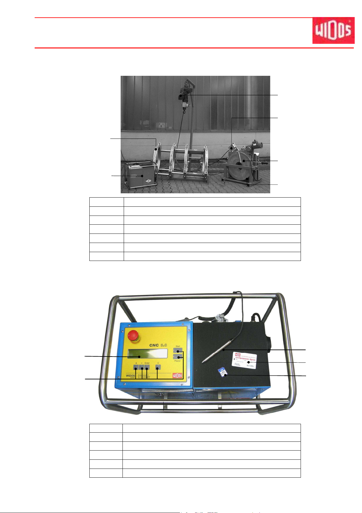
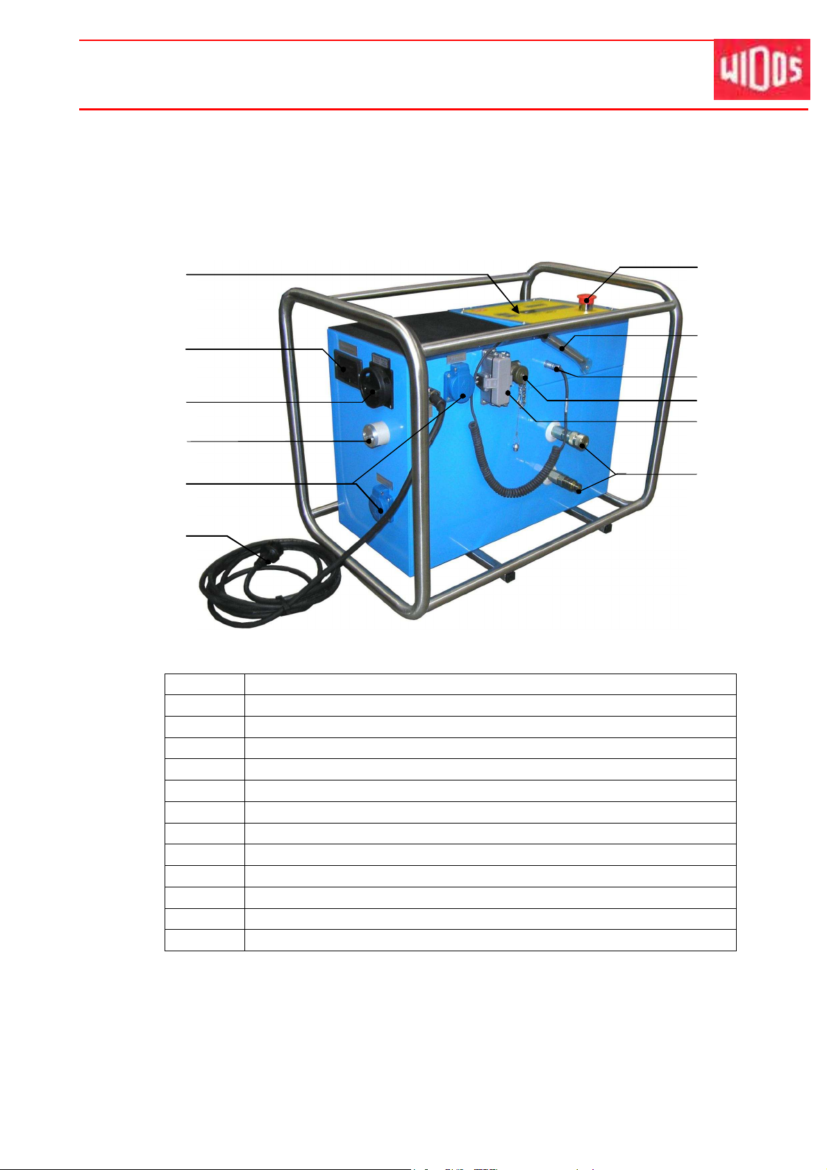
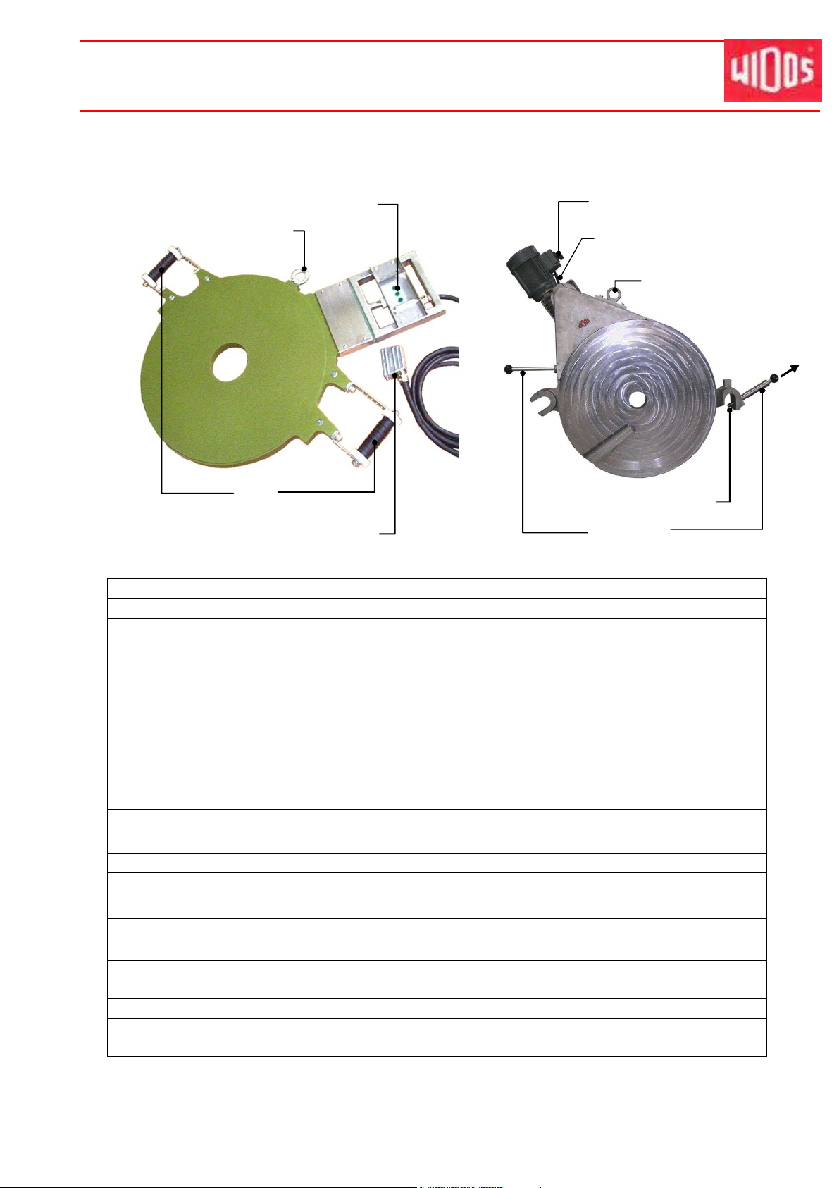
1.4. Machine overview
3
1
No. Denomination
1 Basic machine
2 Control unit
3 Lift off device (optional)
4 Heating element
5 Planer
6 Reception box
Ku nststo ffschwei ßtec hni k
1.5. Structure of the CNC 3.0 control unit
No. Denomination
7 Display
8 Operating fields
9 Barcode reader
10 Pipe data card or general legitimacy card
11 SD card
27.10.2011 Working Instructions WIDOS 6100 CNC 3.0 Page 8 of 76

Description of product Chapter 1
Ku nststo ffschwei ßtec hni k
1.6. Designation of the product
The product is designated by type labels.
The type labels are attached at the control unit, at the heating element, at the planer and at the
basic machine.
They contain the type, the serial number and the year of construction of the machine.
1.6.1. Technical data
All important technical data of each single component are listed.
This allows a quick information about working capacity and structure.
1.6.1.1. WIDOS CNC 3.0 General data
Weight (without transport box):
Dimensions (l x w x h):
450 kg
appr. 630x430x510 (mm)
Covering: 16 A
Voltage:
400 V (± 10%)
Frequency: 50 Hz
Phase shift: appr. 18°
Control voltage: 5 V
Insulation system: IP 44
Hydraulic oil tank: appr. 1 l
Attached elements: Connection cable with CEE - motor protective plug 16 A
Power of emergency set: 6.5 kVA / 400 V/3~
Emissions - Noises exceeding 80 dB (A) may occur; during planing it
is obligatory to wear ear protection!
- When using the named pipe materials and when welding
below 260°C no toxicant damp arises
Ambient conditions in the welding
area
- take care for cleanness (no dust at the welding area)
- if secured by an appropriate measurement that allowed
conditions for welding are indicated, it is possible to work
in any outside temperature condition as far as the welder
is not constrained in its manual skill.
- avoid humidity, if necessary use a welding tent
- avoid strong sun rays influence
- protect from wind, shut the pipe ends
Electro motor and pump:
Power: 0,56 kW
Current: 4,7 A
Driving speed: 2720 rpm
Max. working pressure of the
110 bar
pump:
Working pressure: 100 bar
Volume flow: 3,5 l/min.
27.10.2011 Working Instructions WIDOS 6100 CNC 3.0 Page 9 of 76

Description of product Chapter 1
1.6.1.2. Basic frame
Material frame: Construction steel
Material clamping inserts: Aluminium
Weight: appr. 226 kg
Cylinder-Ø: 60 mm
Piston rod-Ø: 50 mm
Stroke length of cylinder: 300 mm
Max. force: (F=P*A) 17,30 kN (at 100 bar)
Velocity os piston rod: 3,4 cm/s
1.6.1.3. Heating element
Power: 6,0 kW
Voltage: 400 V (± 10 %)
Current: 15 A
Frequency: 50 Hz
Outside-Ø: 684 mm
Surface: nonstick-coated
Attached elements: - electronic temperature control
- control lamps
- cable with 16 pole plug
Weight: appr. 36 kg
1.6.1.4. Planer
Ku nststo ffschwei ßtec hni k
Motor: Alternating current motor
Power: 1.1 kW
Voltage: 400 V (± 10 %)
Current: 3,5 A
Frequency: 50 Hz (± 10 %)
Driving speed appr. 140
Weight: appr. 103 kg
Attached elements: - cable with plug CEE 16A
- locking device
1.6.1.5. Reception box
Dimensions: 870 x 610 x 740 mm
Weight: appr. 62 kg
See spare parts list for order numbers and single parts
27.10.2011 Working Instructions WIDOS 6100 CNC 3.0 Page 10 of 76
Description of product Chapter 1
Ku nststo ffschwei ßtec hni k
1.7. Emergency power supply (optional)
In order to avoid an abortion of the welding in case of power failure during the cooling time, a
lead accumulator is provided in the control (12 V / 3.4 Ah).
1.8. Equipment and accessories:
Following accessories are part of the delivery:
5 - General legitimacy card
1 - Key for front plate / hydraulic system
1 - SD card (64 MB storage capacity)
1 - Tool bag for 10 parts
1 - Socket wrench SW 27
1 - Allan key, angle size 12
1 - Allan key with T-grip size 7
1 - Torx screw driver T10
Following optional accessories are available on request:
- Pipe data card
- Program WICON for reading out the data (possibility of displaying included in SD-card)
- Gas legitimacy card
- ISO legitimacy card
27.10.2011 Working Instructions WIDOS 6100 CNC 3.0 Page 11 of 76
WIDOS Einsteinstr. 5 Phone +49 (0) 71 52 99 39 - 0
W. Dommer Söhne GmbH D-71254 Ditzingen-Heimerdingen Fax +49 (0) 71 52 99 39 - 40
Website: www.widos.de Email: info@widos.de
Ku nststo ffschwei ßtec hni k
2. Safety rules
The base for the safe handling and the fault-free operation of this machine is the knowledge of
the basic safety indications and rules.
• These working instructions contain the most important indications to run the machine safely.
• The safety indications are to be followed by all persons working on the machine.
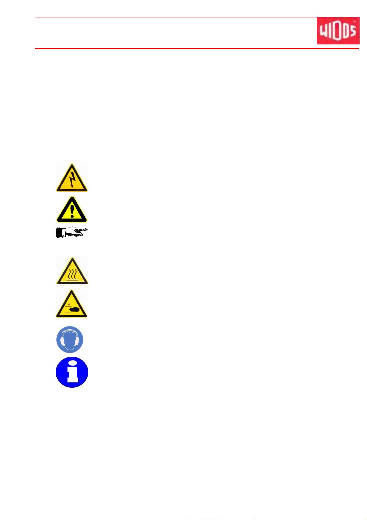
2.1. Explanation of the symbols and indications
In the working instructions, following denominations and signs are used for dangers:
This symbol means a possible danger for the life and the health of persons.
• The disrespect of these indications may have heavy consequences for the
health.
This symbol means a possible dangerous situation.
• The disrespect of these indications may cause light injuries or damages on
goods.
This symbol gives important indications for the proper use of the machine.
• The disrespect of these indications may conduct to misfunctions and damages
on the machine or on goods in the surrounding.
This symbol means a possible dangerous situation due to hot surfaces.
• The disrespect of these indications may conduct to heavy burns, respectively to
self-ignition or even fire.
This symbol means a possible dangerous situation by moving parts of the
machine
• The disrespect of these indications may cause heavy crushings of parts of the
body resp. damages of parts of the machine.
This symbol means a possible risk of injury by noises exceeding 80 dB(A).
• Ear protection is obligatory
Under this symbol you get user tips and particularly useful information.
• It is a help for using all the functions on your machine in an optimal way and
helps you to make the job easier.
The regulations for the prevention of accidents are valid (UVV).
2.2. Obligations of the owner
The owner is obliged only to let persons work at the machine, who
• know about basic safety and accident prevention rules and are instructed in the handling of
the machine, as well as who
• have read and understood the safety chapter of this manual and certify this by their signature.
27.10.2011 Working Instructions WIDOS 6100 CNC 3.0 Page 12 of 76

Safety rules Chapter 2
The safety-conscious working of the staff has to be checked in regular intervals.
2.3. Obligations of the worker
All persons who are to work at the machine are obliged before working:
• to follow the basic safety and accident protection rules.
• to have read and understood the safety chapter and the warnings in this manual and to
confirm by their signature that they have well understood them.
• to inform themselves about the functions of the machine before using it.
2.4. Measures of organisation
• All equipment required for personal safety is to be provided by the owner.
• All available safety equipment is to be inspected regularly.
2.5. Information about safety precautions
Ku nststo ffschwei ßtec hni k
• The working instructions have to be permanently kept at the place of use of the machine.
They are to be at the operator's disposal at any time and without effort.
• In addition to the manual, the common valid and the local accident protection rules and
regulations for the environmental protection must be available and followed.
• All safety and danger indications on the machine have to be in a clear readable condition.
• Every time the machine changes hands or is being rent to third persons, the working
instructions are to be sent along with and their importance is to be emphasized.
2.6. Instructions for the staff
• It must be clearly defined who is responsible for transport, mounting and dismounting, starting
the operation, setting and tooling, operation, maintenance and inspection, repair and
dismounting.
• Only skilled and trained persons are allowed to work at the machine.
• A person who is being trained may only work at the machine under supervision of an
experienced person.
2.7. Dangers while handling the machine
The heating element butt welding machine WIDOS 6100 CNC 3.0 is constructed according to
the latest technical standard and the acknowledged technical safety rules.
However, dangers for the operator or other persons standing nearby may occur. Also material
damages are possible.
The machine should only be used
• According to the purpose oriented usage
• In safety technical impeccable status
Disturbances, which may affect the safety of the machine must be cleared immediately.
27.10.2011 Working Instructions WIDOS 6100 CNC 3.0 Page 13 of 76
Safety rules Chapter 2
Ku nststo ffschwei ßtec hni k
Only skilled persons are allowed to work at electrical appliances.
• The electrical equipment of the machine has to be checked regularly.
Loose connections and damaged cables have to be replaced immediately.
• All electric tools (heating element, planer, basic machine with clamps and control unit)
have to be protected from rain and dropping water (if need be use a welding tent).
• According to VDE 0100, the use on construction sites is only allowed with a power distributor
with a FI-safety switch.
• Replace damaged front foil at the control unit in order to avoid water coming in.
System parts and pressure hoses should be made pressureless before beginning
of any repair works.
There is a danger of injuring the eyes by hydraulic oil squirting out. The hydraulic oil
can be hot !
• Damaged hydraulic hoses have to be immediately replaced.
• Make a visual inspection of the hydraulic hoses before each work beginning.
• The hydraulic oil is inedible !
• The hydraulic oil has to be handled and disposed of properly.
2.8. Specific dangers
2.8.1. Danger of stumbling over hydraulic and electric wires
Make sure that nobody has to step over the cables.
Make sure that the cables lay in such a way that the danger is maintained in a
minimum. Do not squeeze, buckle, etc. the cables. Avoid the hydraulic cables from
being heated up (increase of pressure!).
2.8.2. Danger of catching clothes by the planer
You can cut yourself or even get bones broken!
For some machines the planer may shortly turn when switching the machine on!
• Only wear clothes tight to the body.
• Do not wear rings or jewellery during the work.
• If necessary wear a hair-net.
• Always put the planer back into the reception box after and before each use.
• Only transport the planer at the handle or eye bolt. Do not touch the surfaces.
2.8.3. Risk of injury by noises
Noises exceeding 80 dB (A) may occur; during planing it is obligatory to wear ear
protection!
27.10.2011 Working Instructions WIDOS 6100 CNC 3.0 Page 14 of 76
Safety rules Chapter 2
2.8.4. Danger of being burnt by heating element and welding area
You can burn parts of your body and inflammable materials can also be ignited!
The heating element is heated up to more than 200°C!
• Do not touch the surfaces of the heating element.
• Do not leave the heating element unsupervised.
• Take enough safety distance to inflammable materials.
• Do wear safety gloves.
• Always put the heating element back into the reception box after and before each use.
• Only transport the heating element at the handle.
2.8.5. Danger of squeezing by clamping devices and guideways
There is a danger of serious injuries: on the one hand between the inner clamping
devices and on the other hand between the outer clamping device and the end of
the guideway.
• Do not stand or put hands between clamped pipe ends.
• Do not stand or put hands between the inner clamping tools with not yet clamped pipes.
• Do not block opening and closing of the machine sledge.
2.9. Structural modifications on the machine
Ku nststo ffschwei ßtec hni k
• No modifications, extensions or reconstructions may be made on the machine without
permission of the manufacturer. In cases of non-compliance, any guarantee and liability
demands shall expire (see chapter 2.5).
• Machine parts which are not in a perfect condition are to be replaced immediately.
• Only use original WIDOS spare and wear parts.
• In case of purchase orders please always state the machine and version number !
2.10. Warranty and liability
Fundamentally our "General Sales and Delivery Conditions" are valid.
They are at the owner's disposal latest when signing the contract.
Guarantee and liability demands referring to personal injuries or damages on objects are
excluded if they are caused by one or several of the following reasons:
• not using the machine according to the prescriptions
• inexpert building-up, starting, operating, maintenance and transport of the machine
• running the machine with defective or not orderly mounted safety appliances
• ignoring the information given in this manual
• structural modifications on the machine without permission
• unsatisfactory checking of parts of the machine, which are worn out
• repairs performed in an inexpert way
• In case of catastrophes and force majeure
27.10.2011 Working Instructions WIDOS 6100 CNC 3.0 Page 15 of 76
WIDOS Einsteinstr. 5 Phone +49 (0) 71 52 99 39 - 0
W. Dommer Söhne GmbH D-71254 Ditzingen-Heimerdingen Fax +49 (0) 71 52 99 39 - 40
Website: www.widos.de Email: info@widos.de
Ku nststo ffschwei ßtec hni k
3. Functional description
The WIDOS CNC 3.0 control unit performs a butt welding process with the plastic welding
machine WIDOS 6100 after entering the type of material, the pipe diameter and the pipe wall
thickness.
The welding processes are recorded and can be printed out in a short or a long version over the
parallel interface, or be saved on a PCMCIA card or be transmitted over the serial interface e.g.
onto a laptop by means of the program WICON.
The corresponding pipe data are entered manually over the operation field or alternatively read
with the barcode reader.
Welding with the WIDOS 6100 CNC 3.0 works as follows:
The plastic pipes are clamped by means of the clamping devices (basic machine) and the pipe
ends are cut plane and parallel by means of the planer.
As soon as the pipes are plane and parallel and the misalignment is smaller than 0,1 X pipe wall
thickness you can start welding.
The heating element has to be cleaned and checked before insertion and the desired
temperature prescribed by the DVS must have been reached.
The clamped pipes drive under pressure in direction of the heating element and are heated up
under the defined adjustment pressure (adjusting), the duration of the adjustment is called
adjusting time.
During the adjustment the bead prescribed by the DVS is performed.
After reaching the prescribed bead height, the control unit automatically switches into the
heating time.
During the heating time the basic machine is in a pressureless state and the pipe ends are
heated.
After expiration of the heating time, the sledges move apart and the heating element should be
removed as fast as possible.
The time period between the removal of the heating element and the closing of the pipes is called
change over time.
After the maximum time prescribed by the DVS, the pipe ends are driven together and a
continuous welding pressure is built up.
The pipe then cools down under the prescribed welding pressure (cooling time).
After completion of the cooling time, the pressure on the pipe is automatically released and the
welded pipe can be unclamped.
The welding process is completed.
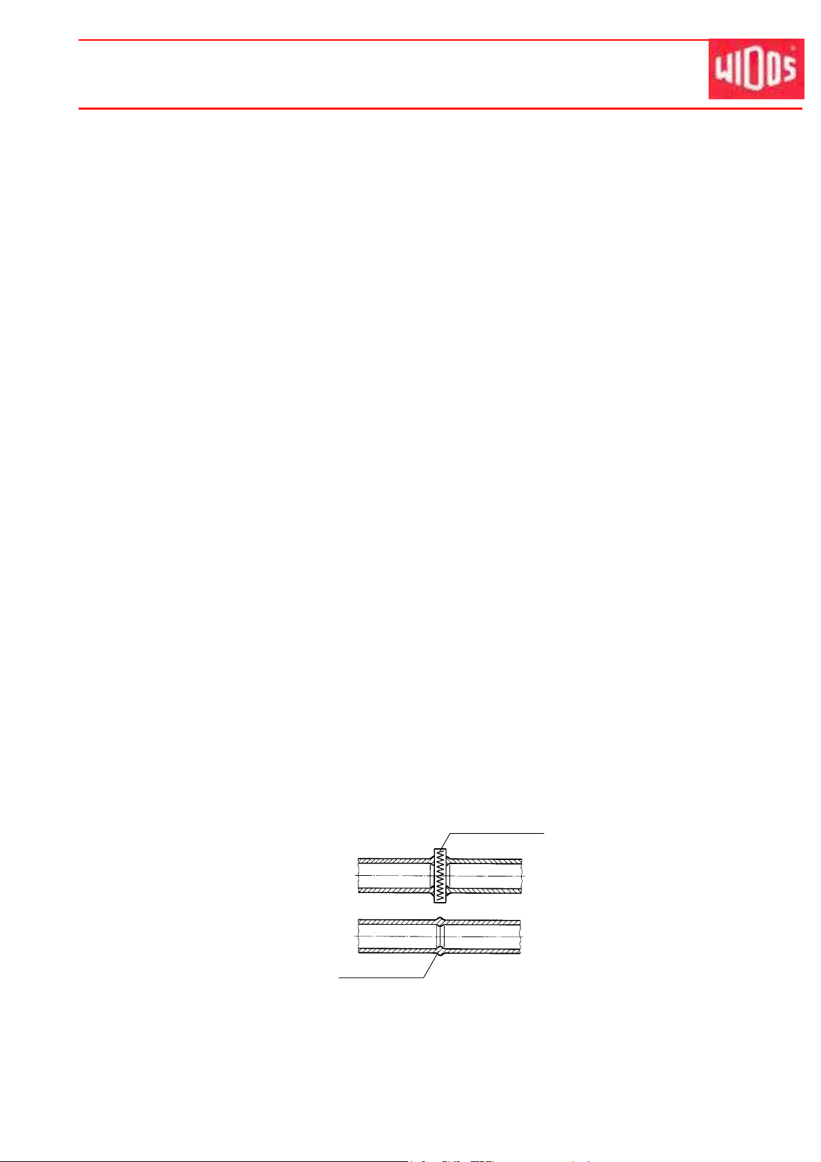
Finished welded joint with
internal and external bead
Heating element heats the pipes
up to welding temperature
27.10.2011 Working Instructions WIDOS 6100 CNC 3.0 Page 16 of 76
WIDOS Einsteinstr. 5 Phone +49 (0) 71 52 99 39 - 0
3
8
10
W. Dommer Söhne GmbH D-71254 Ditzingen-Heimerdingen Fax +49 (0) 71 52 99 39 - 40
Website: www.widos.de Email: info@widos.de
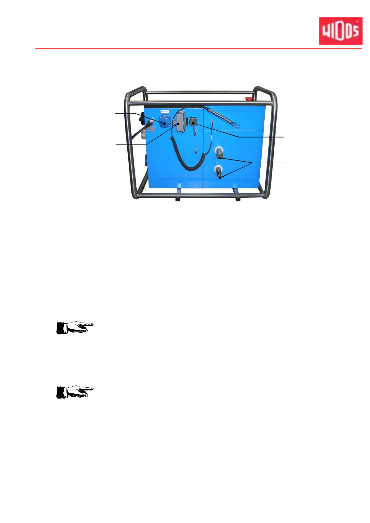
4. Operating and indicating elements
4.1. Elements on the CNC 3.0 control unit
2
5
6
No. Denomination
1 Operating field with display
2 Reafing unit for SD card
3 Main switch
4 Outside temperature sensor
5 Plug box for planer
6 Main connection cable for the control unit
7 EMERGENCY-Stop push button
8 Barcode reader
9 Connection for barcode reader
10 Connection for the travel sensor
11 Plug box with safety stirrup for heating element
12 Connections for hydraulic hoses
Ku nststo ffschwei ßtec hni k
7
9
11
12
27.10.2011 Working Instructions WIDOS 6100 CNC 3.0 Page 17 of 76
Operating and indicating elements Chapter 4
Ku nststo ffschwei ßtec hni k
4.2. EMERGENCY-stop push button
There is an EMERGENCY-Stop push button (chapter 4.1 No. 9) on the CNC control unit, for
interrupting the working process if the work piece, tools or persons are endangered by the
working pressure.
• The EMERGENCY-Stop push button snaps when it is operated.
The display then shows:
## emergency stop ##
• In case the EMERGENCY-Stop push button was pushed, the system is pressure-less and the
sledge can only be moved manually.
• After elimination of the danger the EMERGENCY-Stop push button must be unlocked again
by turning it in direction of arrow and the functions of buttons <+> and <-> (open and close the
sledge) are possible again.
• For a new welding process, the main switch must be switched on and off again.
There is the danger of being burnt by the heating element cooling down very
slowly.
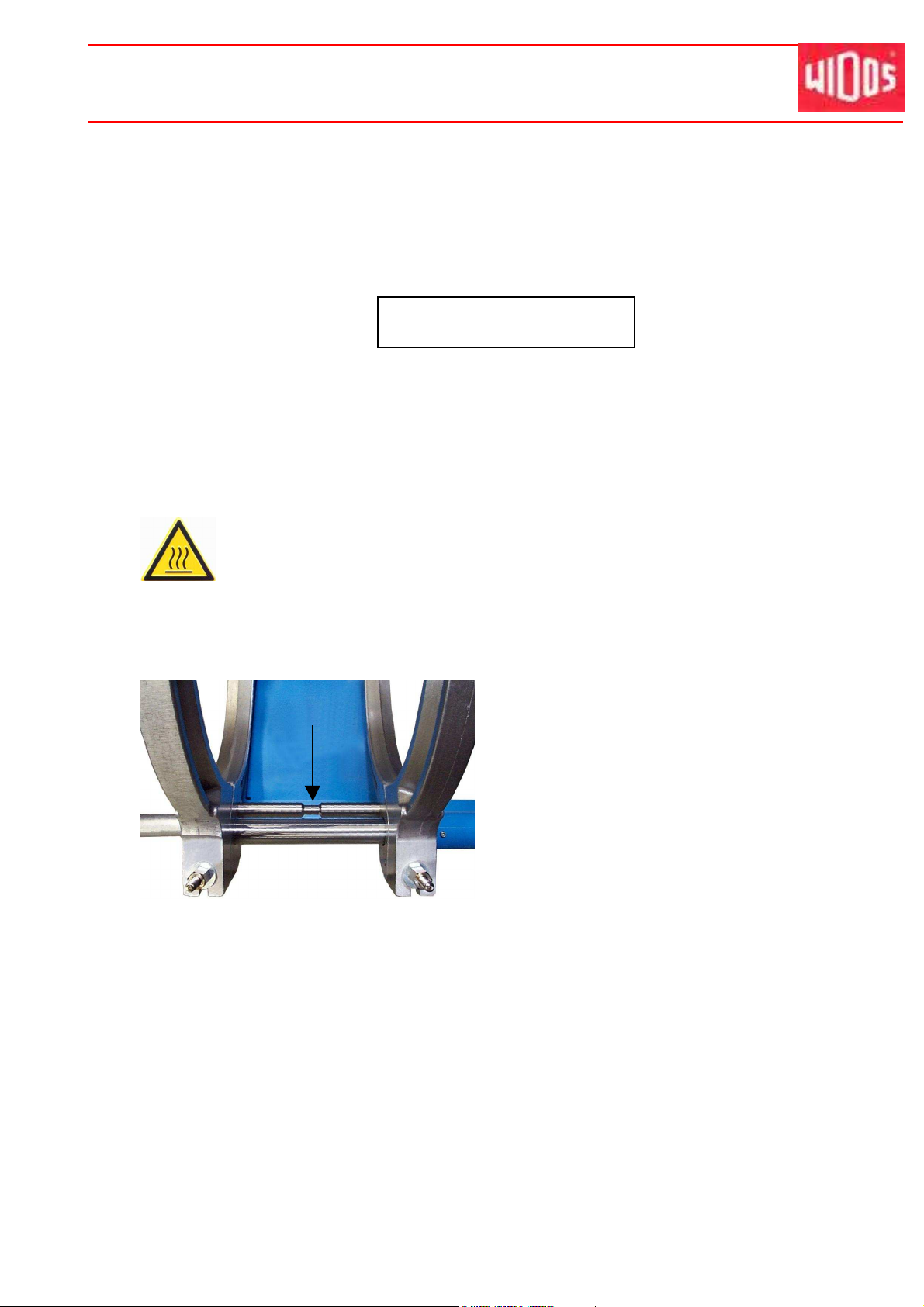
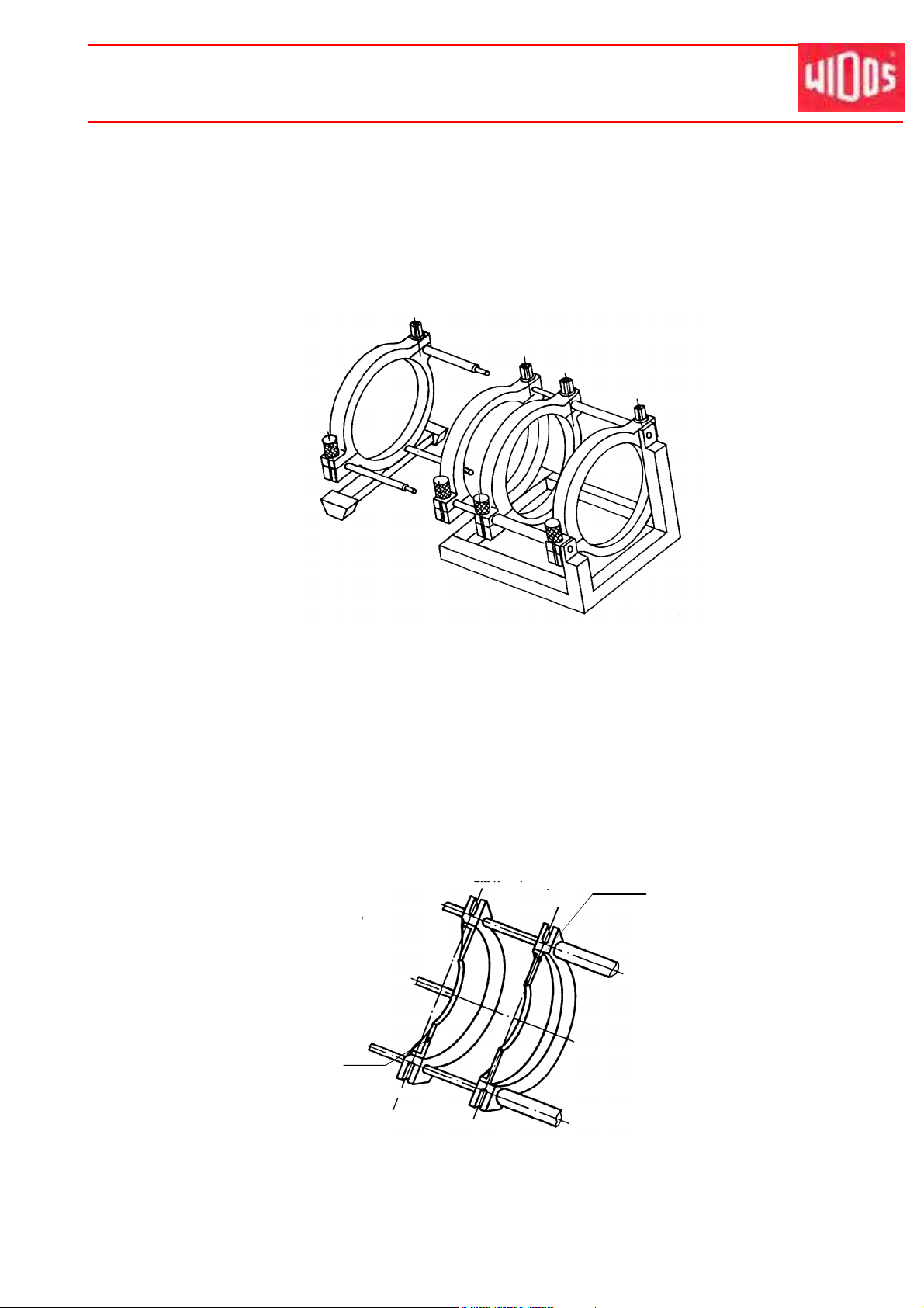
4.3. Separating device for heating element
There is a tear-off bar mounted between the
movable and the fixed clamping shells on the
basic machine. It prevents the heating element
from sticking to the heated-up pipe ends.
When inserting the heating element take care
that it lies in the zone of the throat of the tearoff bar (see arrow).
27.10.2011 Working Instructions WIDOS 6100 CNC 3.0 Page 18 of 76
Operating and indicating elements Chapter 4
4.4. Elements on the heating element and the planer
Ku nststo ffschwei ßtec hni k
Control lamps green (3 pieces)
Eye bolt
Grip
Connecting cable
with 16-pole plug
Name Function
Heating element:
Control lamps,
green
There are 3 different states:
• lightening, only interrupted by short switch-off pulses: the heating
element is being heated up, the desired temperature is not yet reached.
The desired and the actual temperature are displayed alternating on the
display of the control.
• blinking: the temperature of the heating element is maintained by a
pulse-position ratio.
• off: the desired temperature has been exceeded, the
heating element is cooled automatically onto desired temperature, or
the heating element is switched off.
On- / off-switsch
Connecting cable with
plug 16 A CEE
Eye bolt
Locking device
Handlebar
Cable
- Connect the heating element at the corresponding plug box (chapter
4.1, no. 12) on the CNC control unit.
Eye bolt - For lifting / inserting the heating element / planer with the lift-off device.
Grip
- For holding (transporting) the heating element when lifting / removing
Planer:
On/off-switch - During the planing process the planer has to be switched on at the
switch. The planing process is operated by the CNC control.
Cable
- Connect the planer at the corresponding plug box (chapter 4.1, no. 13)
on the CNC control unit.
Handlebar - For holding (transporting) the planer when lifting / removing
Locking device - Locking the planer in basic machine, (In order to remove the planer, pull
handlebar into arrow direction
27.10.2011 Working Instructions WIDOS 6100 CNC 3.0 Page 19 of 76
Operating and indicating elements Chapter 4
Ku nststo ffschwei ßtec hni k
4.5.
• General description
• Safety rules
• Danger indications
• Starting and maintenance
Lift-off device (optional)
see the separate documentation (company ABUS) .
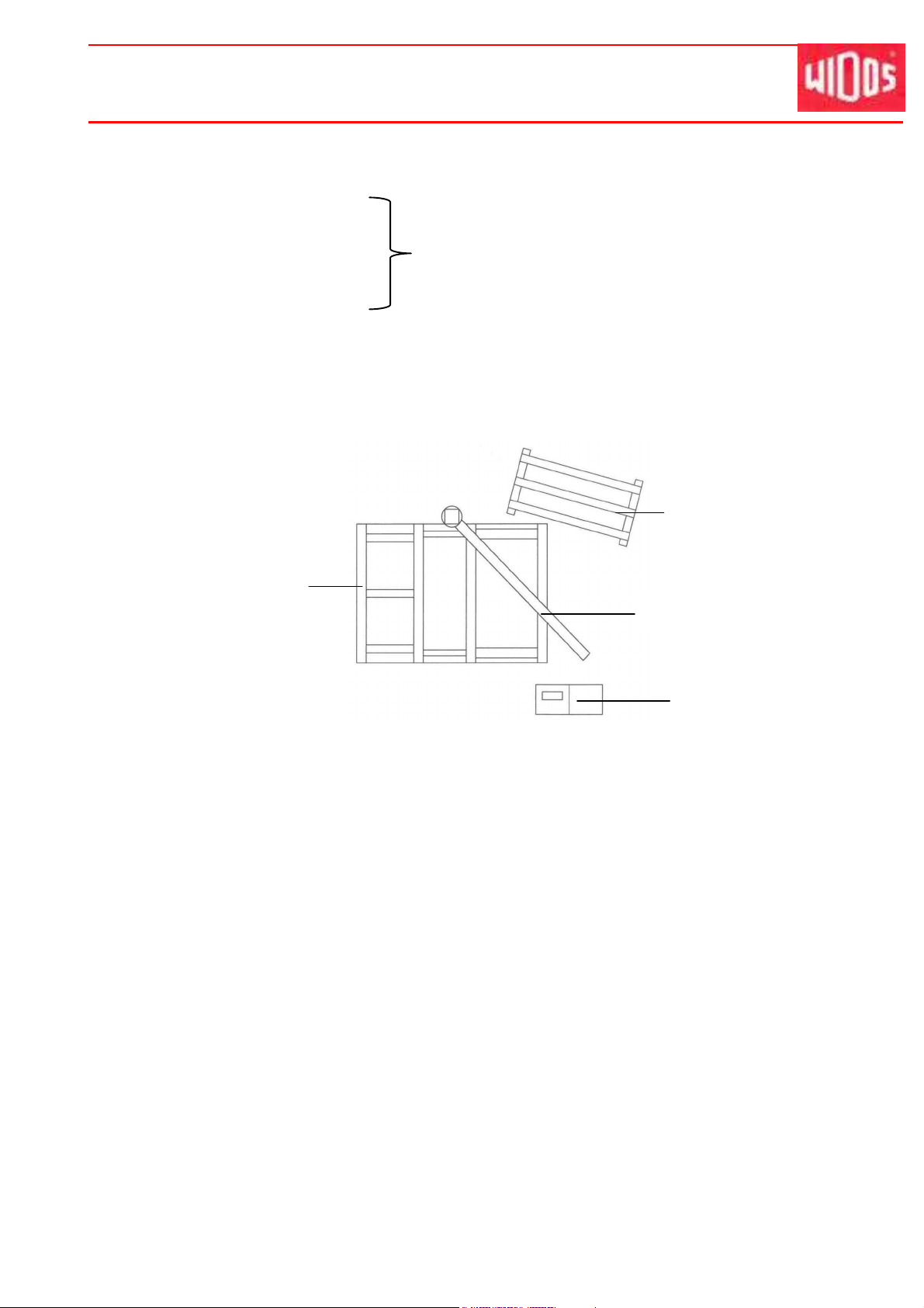
4.5.1. Mounting of the machine
When mounting the machine, follow the positioning sketch:
Basic machine
4.5.2. Mounting the lift-off device
Protection box
Lift-off device
Hydraulic aggregate
• Insert the crane jib into the reception at the backside of the basic machine.
• Loosen the screw and the lock washer at the hook at the top of the mast, hang in the
chain hoist, tighten again lock washer and screw.
• Connect the chain hoist with the mains (230 V/50 Hz).
• The operation of the lift-off device can be started now (see the separate documentation)
4.5.3. Transport
Dismount the chain hoist from the mast for transportation of the machine.
27.10.2011 Working Instructions WIDOS 6100 CNC 3.0 Page 20 of 76
WIDOS Einsteinstr. 5 Phone +49 (0) 71 52 99 39 - 0
W. Dommer Söhne GmbH D-71254 Ditzingen-Heimerdingen Fax +49 (0) 71 52 99 39 - 40
Website: www.widos.de Email: info@widos.de
Ku nststo ffschwei ßtec hni k
5. Starting and operating
The instructions of this chapter are supposed to initiate in the operation of the machine and lead
during the appropriate starting of the machine.
This includes: - the safe operation of the machine
- using all the possible options of the machine
- economic operation of the machine
5.1. Safety indications
• The machine should only be operated by initiated and authorized persons.
For the qualification, a plastic welding exam can be taken according to DVS and DVGW.
• In situations of danger for persons and the machine, the EMERGENCY-Stop push button
or the main switch have to be activated immediately.
• After completion of the welding work and during breaks the machine has to be switched
off. Further take care that no unauthorized person has access.
• According to VDE 0100, the use on construction sites is only allowed with a power
distributor with a FI-safety switch.
Check the oil level of the hydraulic system before each starting of the control unit in
order to avoid damages on the pump.
If necessary, add hydraulic oil of the quality HLPD 32.
The heating element surfaces must be clean, especially non greasy, therefore they
need to be cleaned shortly before each welding or in case of dirtiness by means of
a fibre-free paper and a cleaning agent (e.g. technical pure alcool or pipe
cleaning tissues which are available at the WIDOS company).
The anti-adhesive coating of the heating element must remain undamaged in the
working area.
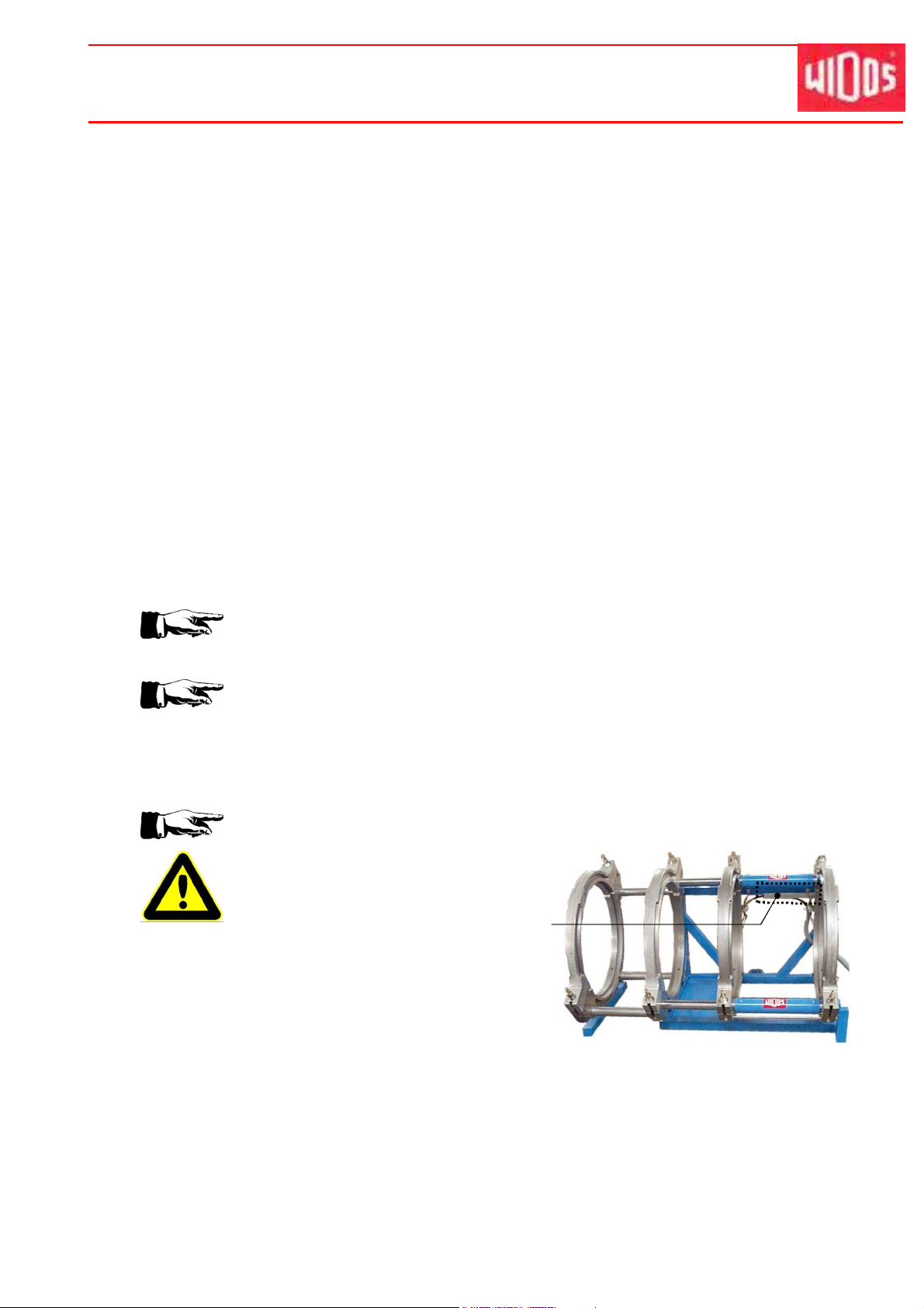
Take care that all hydraulic and electric connections are connected.
Never lift or transport the basic machine
at path measuring system!
Path measuring system
•
Take into account the surrounding conditions:
The welding may not be performed under direct sun rays influence, use a welding
umbrella if necessary.
•
If the surrounding temperature is under 5° C, measures have to be taken:
Use a welding tent or preheat the pipe ends if necessary.
27.10.2011 Working Instructions WIDOS 6100 CNC 3.0 Page 21 of 76
Starting and operating Chapter 5
5.2. Replacing the reduction inserts
• Unscrew the mounted reduction inserts.
• Screw the reduction inserts with the corresponding diameter into the clamping devices.
• If necessary (e.g. for T-pieces) the outer fixed clamping device can be dismantled by
unscrewing the three hexagon socket screws.
Ku nststo ffschwei ßtec hni k
Dismantling of the outer fixed clamping device
5.2.1. Using small reduction inserts
Small reduction inserts:
• Pipe fittings often have only a short straight surface area on which they can be clamped.
• Fittings mostly need to be clamped in the inner clamping devices with the small reduction
inserts.
• When fittings are to be welded (bends, T-pieces etc.), the inner small reduction insert can
also be used flush to the inside or to the outside.
Shown here:
Small reduction insert,
flush to the inside
(for bends, T-pieces)
R
Small reduction insert,
centered (for pipes)
27.10.2011 Working Instructions WIDOS 6100 CNC 3.0 Page 22 of 76
Starting and operating Chapter 5
F
G
H
I
Ku nststo ffschwei ßtec hni k
5.3. Connection with the basic machine
• Connect the hydraulic hoses and travel measuring systems of the basic machine at the CNC
3.0 (F and G).
• Connect the heating element at the CNC 3.0 (H) by means of the special plug and secure it
by means of the safety stirrup.
• Connect the planer to the corresponding plug box of the CNC 3.0 (I).
• Connect the power line plug of the CNC 3.0 to the mains, and be sure to have a correct
mains voltage (400 V / 50 Hz).
5.4. Operation with Emergency Power Supply
Do not connect any other current consumers to the emergency power supply.
Current consumers, such as drilling machines, fluorescent lamps or motors,
can generate spikes (more than 1000 V) which can disturb the welding
process and might destroy the welding aggregate!
The emergency power supply should be maintained periodically.
For further details see the working instructions of the emergency power
supply.
Important: first start the emergency power supply and then the other current
consuming devices.
27.10.2011 Working Instructions WIDOS 6100 CNC 3.0 Page 23 of 76
Starting and operating Chapter 5
Ku nststo ffschwei ßtec hni k
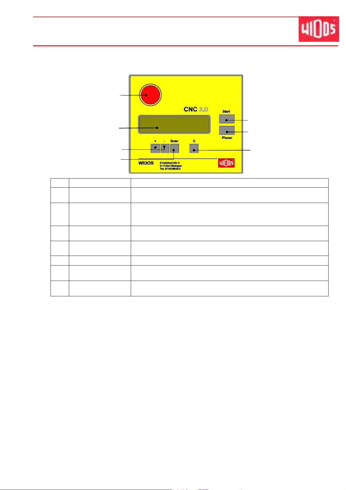
5.5. Description of the Display
1
3
2
5
6
4
7
No. Buttons Function
1 EMERGENCY-OFF
push button
2 Display Shows the actual parameters and status messages (for welding and
3 Start Start the welding functions.
4 Planer
5 + / - Change the parameters.
6 Enter Enter / quit the menu "parameter setting".
7 C Abort the welding process
The EMERGENCY-OFF push button snaps when it is operated, the
machine stops (see also chapter 4.2).
programming).
Several values can be displayed simultaneously.
Confirm the new set parameters.
Start the planing process (on/off switch on the planer must be switched
on).
Confirm the parameters.
Step back at "parameter setting".
5.6. Accessories for Reading the Data in and out
5.6.1. Legitimacy Cards
There are 3 different types of cards which are accepted by the barcode reader:
(1) With each supplied machine a general legitimacy card (5 pieces) is basically supplied with.
It is of white colour and gives the legitimation to operate all functions (including special
functions).
(2) Pipe data card: on this card all parameters of a pipe are memorized (parameters are
stored in the control unit). For ordering the card, the pipe diameter, the pipe-wall thickness
and the material should be specified.
(3) Optionally, a gas legitimacy card (yellow) can be supplied. With this card, no changes can
be made in the system. The computer will ask automatically for a pipe data card for setting
the pipe data.
(4) Optionally, a ISO legitimacy card can be supplied. It is of white colour and gives the
legitimation to operate all functions (including special functions).
• Protect the cards from wetness and dirtiness.
• Do not bend the cards or expose them to high magnetic fields.
• The card is not transmissible.
27.10.2011 Working Instructions WIDOS 6100 CNC 3.0 Page 24 of 76
 Loading...