

WIDOS Einsteinstraße 5 Phone +49 (0) 71 52 / 99 39 - 0
W. Dommer Söhne GmbH D-71254 Ditzingen-Heimerdingen Fax +49 (0) 71 52 / 99 39 - 40
info@widos.de Internet: www.widos.de
Kunststoffschweißtechnik
Working instructions
Translation
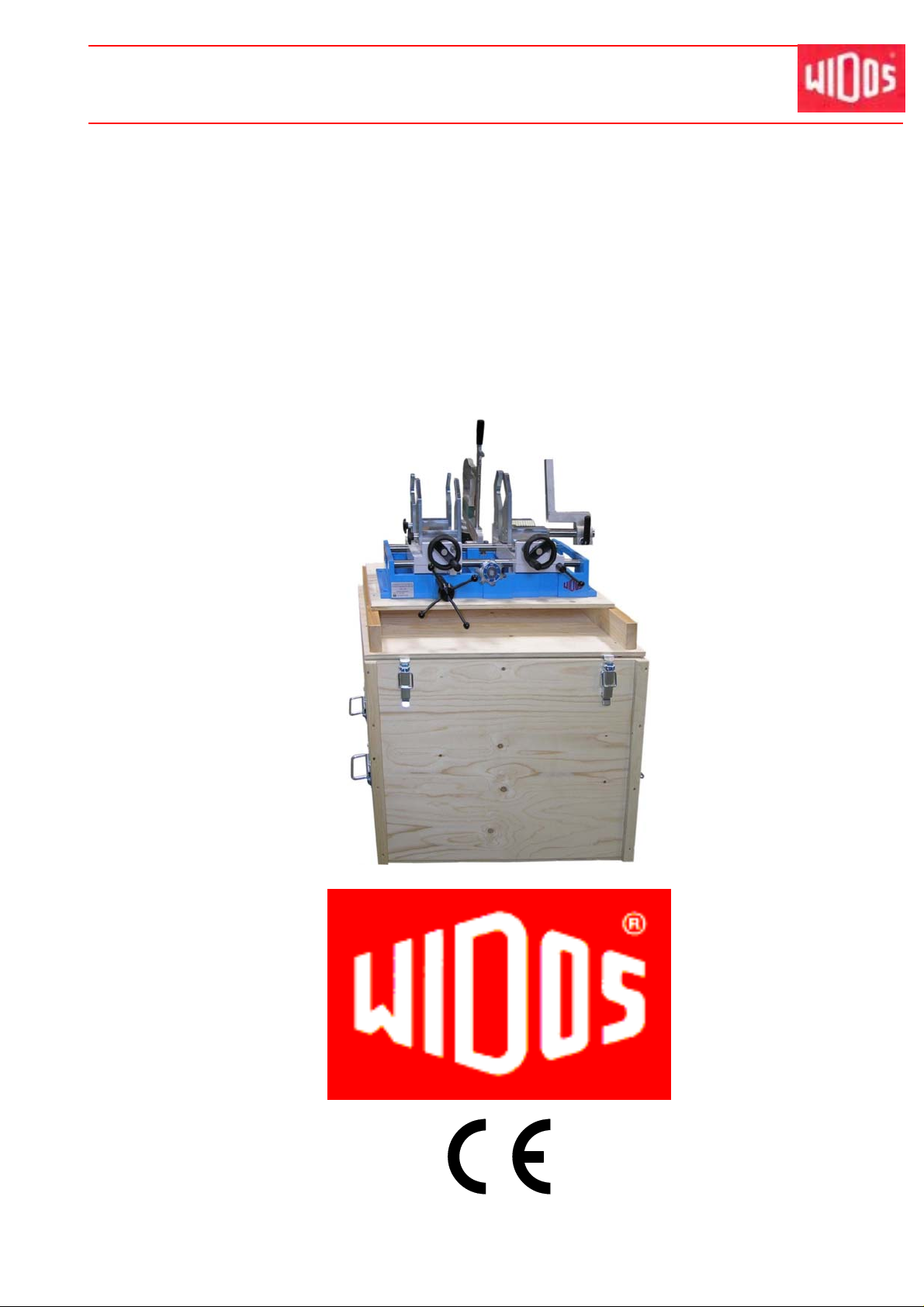
Heating element socket welding machine
WIDOS 3511
Keep for further use!
20.08.14 Working instructions WIDOS 3511 Page 1 of 39

Introduction
Kunststoffschweißtechnik
Model: Heating element socket welding machine
Type:
Serial number / year of construction:
WIDOS 3511
see type label
Customer entries
Inventory No.:
Location:
Order of spare parts and sales service:
Address of manufacturer WIDOS
W. Dom mer Söhne GmbH
Einsteinstr. 5
D-71254 Ditzingen-Heimerdingen
Phone: +49 (0) 71 52 / 99 39 - 0
Fax: +49 (0) 71 52 / 99 39 - 40
Address of subsidiary companies:
WIDOS
WIDOS GmbH W. Dommer Söhne AG
An der Wiesenmühle 15 St. Gallerstr. 93
D-09224 Grüna / Sachsen CH-9201 Gossau
Phone: +49 (0) 3 71 / 8 15 73 - 0 Phone: +41 (0) 79 432 5737
Fax: +49 (0) 3 71 / 8 15 73 - 20
20.08.14 Working instructions WIDOS 3511 Page 2 of 39

Introduction
Kunststoffschweißtechnik
Purpose of the document
These working instructions give you information about all important questions which refer to
the construction and the safe working of your machine.
Just as we are, you are obliged to engage in these working instruction s, as well.
Not only to run your machine economically but also to avoid damages and injuries.
Should questions arise , contact our advisers in the factory or in our subsidiary compa nies.
We will help you with pleasure.
According to our interest in making our products and working instructions continuously better,
we kindly ask you to inform us about problems and defects which occur in exercise.
Thank you.
Structure of the working instructions
The working instructions are arranged in chapters, which belong to the different using phases
of the machine.
Therefore the searched information can be found easily.
8/20/2014 WIDOS
W. Dom mer Söhne GmbH
Einsteinstraße 5
D-71254 Ditzingen-Heimerdingen
All rights reserved.
Reprinting only allowed with permission of the corporation.
Any changes prior to technical innovations.
20.08.14 Working instructions WIDOS 3511 Page 3 of 39

Contents
Kunststoffschweißtechnik
1.
DESCRIPTION OF PRODUCT ............................................................................6
1.1. Usage and purpose-oriented use .........................................................................................6
1.2. Safety measures .....................................................................................................................6
1.3. Conformity ..............................................................................................................................6
1.4. Designation of the product.................................................................................................... 7
1.4.1. Technical data..................................................................................................................7
1.4.1.1. WIDOS 3511 General data ............................................................................. 7
1.4.1.2. Heating element.............................................................................................. 7
1.5. Equipment and accessories .................................................................................................. 8
2. SAFETY RULES ..................................................................................................9
2.1. Explanation of the different symbols...................................................................................9
2.2. Obligations of the owner ..................................................................................................... 10
2.3. Obligations of the worker....................................................................................................10
2.4. Measure of organization......................................................................................................10
2.5. Information about safety precautions ................................................................................ 10
2.6. Instructions for the staff......................................................................................................10
2.7. Dangers while handling the machine................................................................................. 11
2.8. Dangers caused by electric energy....................................................................................11
2.9. Special dangers....................................................................................................................11
2.9.1. Danger of stumbling over electric cables .......................................................................11
2.9.2. Danger of burning at heating element and welding area ...............................................11
2.9.3. Danger of squeezing by clamping tool and guideways.................................................. 12
2.10. Structural modifications on the machine .......................................................................... 12
2.11. Warranty and liability...........................................................................................................12
3. FUNCTIONAL DESCRIPTION ...........................................................................13
4. OPERATING AND INDICATING ELEMENTS................................................... 14
4.1. Elements at the front............................................................................................................14
4.2. Elements on the heating element.......................................................................................15
4.3. Accessories ..........................................................................................................................15
4.4. Clamping tool left for pipe...................................................................................................16
4.5. Clamping tool for fitting.......................................................................................................16
4.6. Support..................................................................................................................................17
5. STARTING AND OPERATING ..........................................................................18
5.1. Starting..................................................................................................................................18
5.1.1. Assembly of the machine...............................................................................................18
5.2. Welding process...................................................................................................................19
6. WELDING LOG AND TABLES ..........................................................................22
6.1. Table for PP...........................................................................................................................22
20.08.14 Working instructions WIDOS 3511 Page 4 of 39

Contents
Kunststoffschweißtechnik
6.2. Table for PVDF ......................................................................................................................22
6.3. Table for PEHD .....................................................................................................................23
6.4. Table for PB (Polybutene) ...................................................................................................23
6.5. Weld log.................................................................................................................................24
7. MAINTENANCE / STORAGE / TRANSPORT ...................................................25
7.1. Maintenance..........................................................................................................................25
7.2. Storage..................................................................................................................................25
7.3. Transport...............................................................................................................................25
7.4. Cleaning of the machine ......................................................................................................25
7.5. Adjusting of the mismatch compensation......................................................................... 26
7.6. Disposal.................................................................................................................................26
8. ELECTRIC DIAGRAMS .....................................................................................27
9. SPARE PARTS LIST .........................................................................................29
9.1. Basic machine ......................................................................................................................29
9.2. Prism clamping tool for pipes .............................................................................................31
9.3. Prism clamping tool for fitting with support .....................................................................33
9.4. Heating element....................................................................................................................35
9.5. Spigot and socket.................................................................................................................37
10. DECLARATION OF CONFORMITY ..................................................................39
20.08.14 Working instructions WIDOS 3511 Page 5 von 39

WIDOS Einsteinstraße 5 Phone +49 (0) 71 52 / 99 39 - 0
W. Dommer Söhne GmbH D-71254 Ditzingen-Heimerdingen Fax +49 (0) 71 52 / 99 39 - 40
info@widos.de Internet: www.widos.de
Kunststoffschweißtechnik
1. Description of product
This chapter gives important basic information about the product and its prescribed use.
All technical details of th e machine are put together as a general arrangement.
1.1. Usage and purpose-oriented use
The WIDOS 351 1 is exclusively designed for the heating element socket welding of pipes and
fittings out of PE, PP an d PVDF with an outside diameter range from 20 mm to 125 mm.
At heating element socket welding, pipe and fitting are welded overlapping.
The heated tool is adjusted to the siz e of the fitting in a way that a joining pressure is built up at
joining.
Heating element socket joints up to 50 mm pipe diameter can be performed manually.
For diameters as from 63 mm, the use of a weldi ng device is necessary due to the high joining
pressure.
The motion for socket welding is con trolled by means of a transport wheel and a toothed rack.
All use of this machine going beyond is not purpose oriented.
The machine is only to be used in a technically perfect condition, as well as purpose oriented,
safety- and danger-conscious in compliance with the working instructions and the relevant
safety regulations (especially the regulations for the prevention of accide nts).
The described plastic welding machine may only be operated, maintained and repaired by
persons trained and informed about the dangers.
The manufacturer is not responsible for any damages cause d by inexpert handling or
operation.
For personal injuries, material and immaterial damages resulting herefrom, only the user is
responsible!
Prescribed use also means:
following all indications in these working instructions and
performing the inspection and maintenance works.
1.2. Safety measures
In case of wrong use, wrong operation or wrong maintenance, the machine itself or products
standing nearby can be damaged or destroyed.
Persons being in the endangered area may be injured.
Therefore these working instructions have to be thoroughly read and the corresponding safety
advices must be necessarily adhered to.
1.3. Conformity
The machine corresponds in its construction to the valid recommendations of the European
Community as well as to the European standard specifications.
The development, manufacturing and mounting of the machine were made very carefully.
20.08.14 Working instructions WIDOS 3511 Page 6 of 39
Description of product Chapter 1
Kunststoffschweißtechnik
1.4. Designation of the product
The product is designated by a type label at basic machine and heating element.
The labels contain the type of the machine, the serial number and the year of construction.
1.4.1. Technical data
1.4.1.1.
Mat erial : PP, PE, PV DF, PB
Pipe diamete r ran ge: OD = 20 - 125 mm (optional up to OD 150mm)
Transport box (l x w x h): 850 x 670 x 680 mm
Total weight: 80 kg
Protection: 16 A
Emissions:
Ambient conditions: - Keep the workshop clean (especially the welding area
WIDOS 3511 General data
- When using the named pipe materials and when
welding below 260° C or 500° F no toxic damp arises.
must be clean)
- If secured by an appropriate measurement that allowed
conditions for welding are indicated, it is po ssible to
work in any outside temperature condition as far as the
welder is not constrained in its man ual skill- Avoid
humidity, if necessary put up a tent
- Avoid strong sun beams
- If it is windy shut the pipe endings
1.4.1.2. Heating element
Power: 1000 Watt 1000 Watt
Vo ltag e: 230 V ( 10%) 110 V ( 10%)
Current: 4,6 A ( 10%) 9,2 A ( 10%)
Wire cross section: 1,5 mm² 1,5 mm²
Frequency: 50 Hz 60 Hz
Attached elements: - electronic temperature
control
- control lamp
- connecting cable with
plug
Weight : approx. 2 kg approx. 2 kg
- electronic temperature
control
- control lamp
- connecting cable with
plug
20.08.14 Working instructions WIDOS 3511 Page 7 of 39

Description of product Chapter 1
1.5. Equipment and accessories
Pieces Denomination
1 Allan key size 5 (screw in / out the clamping elements)
1 Allan key size 4 (for changing the dial)
1 Allan key with T grip, size 6 (for changing spigots and socke ts)
1 set Gripping tools for pipes Ø 20 – 50 mm
1 set Gripping tools for pipes Ø 50 – 125 mm
1 set Gripping tools for fitting Ø 29 – 68 m m
1 set Gripping tools for fitting Ø 75 – 167 mm
1 set Gripping tools for fitting Ø 29 – 68 mm NIBCO (optional)
1 Dial DVS type B (optional)
1 Dial ASTM mm (optional)
1 Dial ASTM inch (optional)
Kunststoffschweißtechnik
20.08.14 Working instructions WIDOS 3511 Page 8 of 39
WIDOS Einsteinstraße 5 Phone +49 (0) 71 52 / 99 39 - 0
W. Dommer Söhne GmbH D-71254 Ditzingen-Heimerdingen Fax +49 (0) 71 52 / 99 39 - 40
info@widos.de Internet: www.widos.de
Kunststoffschweißtechnik
2. Safety rules
A basic premise for working safe ly and without disturbances is the knowledge of the basic
safety signs and safety rules.
These working instructions provide you with the most important information to run the
machine safely.
The safety information must be followed by all persons who work at the machine.
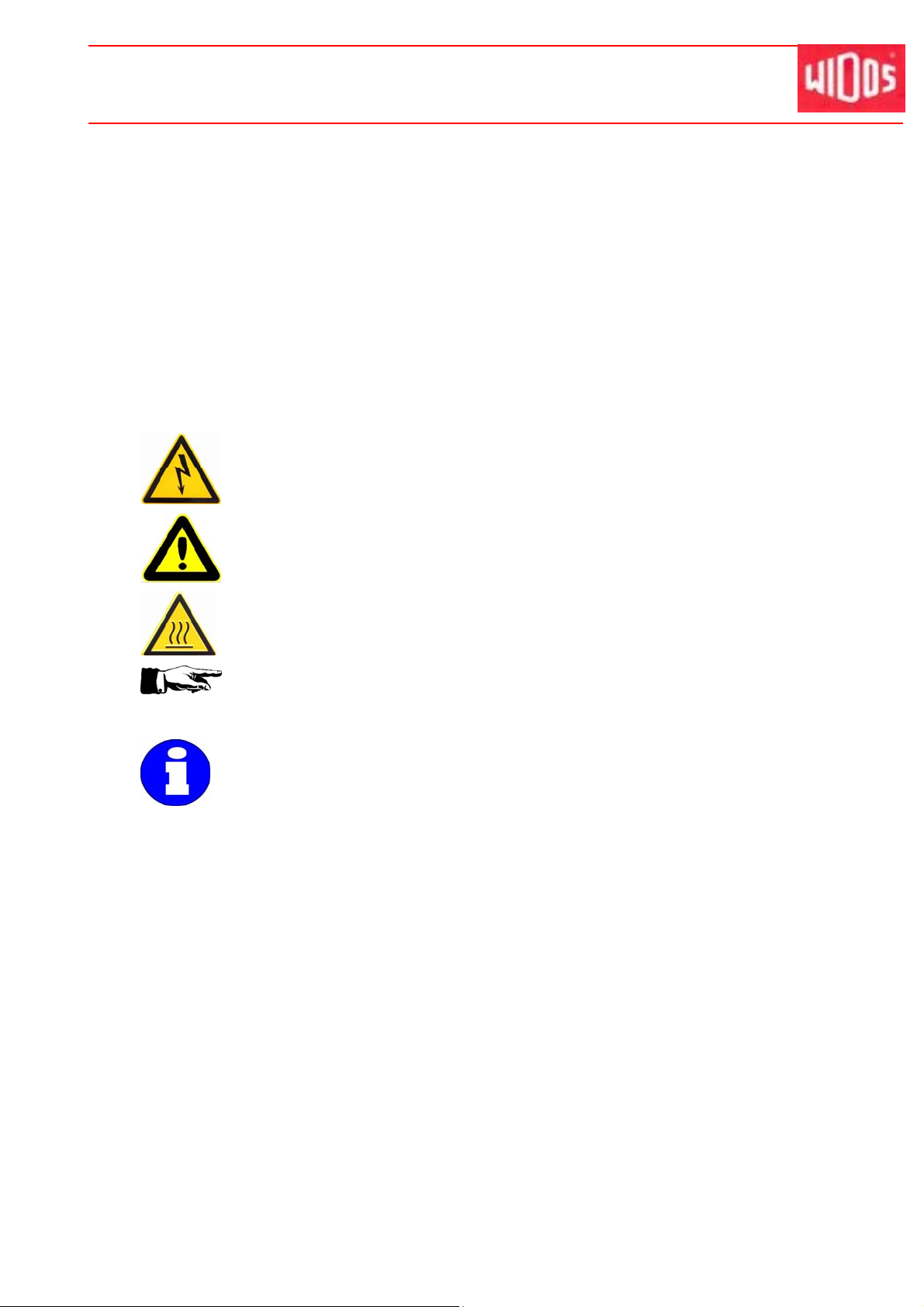
2.1. Explanation of the different sym bols
The working instructions contain the following signs for certain situations:
This symbol means a possibly danger for the life and the health of persons.
The disrespect of these indications may have h eavy consequences for the
health.
This symbol means a possible dangerous situation.
The disrespect of these indications may cause slight injuries or damages on
goods.
This symbol means a possible dangerous situation due to hot surfaces.
The disrespect of these indications may conduct to heavy burns,
respectively to self-ignition or even fire.
This symbol gives important indications for the p roper use of the machine.
The disrespect of these indications may conduct to malfunctions and
damages on the machine or on goods in the sur rounding.
Under this symbol you get user tips and particularly useful information.
It is a help for using all the functions on your machine in an optimal way and
The regulations for the prevention of accidents are valid (UVV).
helps you to make the job easier.
20.08.14 Working instructions WIDOS 3511 Page 9 of 39

Safety rules Chapter 2
Kunststoffschweißtechnik
2.2. Obligations of the owner
The owner is obliged on ly to let persons work at the machine who
know about basic safety and accident prevention rules and are instructed in the handling of
the machine, as well as who
have read and understood the safety chapter of this manual and certify this by their
signature.
The safety-conscious working of the staff has to be checked in regular intervals.
2.3. Obligations of the worker
All persons who are to work at the machine are obliged before working:
to follow the basic safety and accident protection rules.
to have read and understood the safety chapter and the warnings in this manual and to
confirm by their signature that they have well understood them.
to inform themselves about the functions of the machine before using it.
2.4. Measure of organization
All equipment required for personal safety is to be provided by the owner.
All available safety equipment is to be inspected regularly.
2.5. Information about safety precautions
The working instructions have to be permanently kept at the place of use of the machine.
They are to be at the operator's disp osal at any time and without much effort.
In addition to the manual, the common valid and the local a ccident protection rules and
regulations for the environmental protection must be available and followed.
All safety and danger indications on t he machine have to be in a clear readable condition.
Every time the machine changes hands or is being rent to third persons, the working
instructions are to be sent along with and their importance is to be emphasized.
2.6. Instructions for the staff
Only skilled and trained persons are allowed to work at the machine.
It must be clearly defined who is responsible for transport, mounting and dismounting, and
starting the operation.
A person who is being trained may only work at the machine under supervision of an
experienced person.
20.08.14 Working instructions WIDOS 3511 Page 10 of 39
Safety rules Chapter 2
Kunststoffschweißtechnik
2.7. Dangers while handling the machine
The machine WIDOS 351 1 is constructed according to the latest technical standard and the
acknowledged technical safety rules.
However, dangers for the operator or other persons standing nearby m ay occur. Also material
damages are possible.
The machine may only be used
according to the purpose -oriented use
in safety technical impeccable status
Disturbances which may affect the safety of the machine must be cleared immediately
Only skilled persons are allowed to w ork at electrical appliances.
The electrical equipment of the machine has to be checked regularly.
Loose connections and damaged cables have to be replaced immediately.
Protect the heating element and planer from rain and dropp ing water.
According to VDE 0100, the use on c onstruction sites is only allowed with a power
distributor with a FI-safety switch.
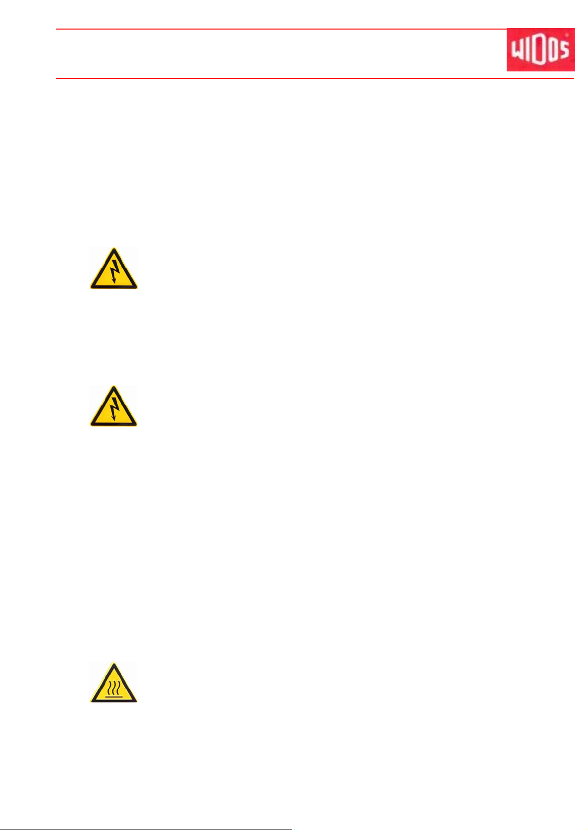
2.8. Dangers caused by electric energy
Only skilled persons are allowed to work at electrical appliances!
The electrical equipment of the machine has to be checked regularly. Loose
connections and damaged cables have to be replaced immediately .
If works at alive parts are necessary, a second p erson has to assist who can disconnect the
machine from the mains if necessary.
The heating element has to be protected from rain and dropping water (if need be use a
welding tent).
According to VDE 0100, the use on c onstruction sites is only allowed with a power
distributor with a FI-safety switch.
2.9. Special dangers
2.9.1. Danger of stumbling over electric cables
Make sure that no person must step over the wires.
Make sure that the cables lie in such a way that the danger is maintained at a minimum.
2.9.2. Danger of burning at heating element and welding area
You can burn yourself, inflammable materials can be ignited!
The heating element reaches temperatures of more than 260° C / 500° F!
Do not touch the surface of the heating element.
Do not leave the surfac es of the heating element unattended.
Take enough safety distance to materials which may be ignited.
Do wear safety gloves.
Only swivel the heating element at the handle.
20.08.14 Working instructions WIDOS 3511 Page 11 of 39

Safety rules Chapter 2
When cleaning the hot h eating element with detergents (e.g. with PE – cleaning agent)
there is the danger of inflammation. For this reas on, please take care that the inflammation
point is above the actual temperature of the heating element. Do not bring any fire sources
(e.g. cigarettes) close thereto.
2.9.3. Danger of squeezing by clamping tool and guideways
There is the danger of serious injurie s. On the one hand between the clamping tools
and on the other hand between the ends of the guideways and the machine slide.
Do not grip between the workpieces.
Do not touch the guide ways.
Kunststoffschweißtechnik
2.10. Structural modifications on the machine
Without permission of the manufacturer, no modifications, extensions or reconstructions
may be performed on the machine. Any non-compliance makes expiring the guarantee and
liability demands (chapter 2.5.).
Machine parts that are not in perfect condition are to be replaced immediately .
Only use original WIDOS spare and wear parts.
In case of purchase orders, please always note the machine and version number!
2.11. Warranty and liability
Fundamentally, our "General sales and delivery conditions" are in force.
They are at the buyer's disposal latest when signing the contract.
Guarantee and liability demands referring to damages of persons or things are excluded if they
are caused by one or several of the following reasons:
Not using the machine according to the prescriptions.
Unprofessional transport, building-up, starting, operating and maintenance of the machine.
Running the machine with defective or not properly mounted safety equipment.
Ignoring the information given in these working instruction s.
Structural modifications on the machine without permission.
Unsatisfactory maintenance of parts of the machine which are worn out.
Unprofessionally performed repairs.
In case of c atastrophes and acts of god.
20.08.14 Working instructions WIDOS 3511 Page 12 of 39

WIDOS Einsteinstraße 5 Phone +49 (0) 71 52 / 99 39 - 0
W. Dommer Söhne GmbH D-71254 Ditzingen-Heimerdingen Fax +49 (0) 71 52 / 99 39 - 40
info@widos.de Internet: www.widos.de
Kunststoffschweißtechnik
3. Functional description
Basically, the international and national standard specifications are
to be fulfilled.
First of all, the two workpieces to be welded are put into the clamping device, the fitting is
clamped at the stop of the clamping device.
Then the zero offset is ef fected and the pipe can be clamped in such a way that both
workpieces can be heated up to welding temperature at the same time (heat-up time) with the
help of a socket or sp igot-shaped heating element.
After swinging out the heating element (change-over time), the workpieces are joined (cooling
time).
The pipe end, heating element and fitting socket are to match each other in size in such a way
that a joining pressure will build up during joinin g.
After expiration of the cooling time, the welded joint can be unclamped, the welding process is
finished.
Principle of heating element socket welding
20.08.14 Working instructions WIDOS 3511 Page 13 of 39

WIDOS Einsteinstraße 5 Phone +49 (0) 71 52 / 99 39 - 0
W. Dommer Söhne GmbH D-71254 Ditzingen-Heimerdingen Fax +49 (0) 71 52 / 99 39 - 40
info@widos.de Internet: www.widos.de
Kunststoffschweißtechnik
4. Operating and indicating elements
4.1. Elements at the front
1
2
3
No. Denomination / function
1 Clamping tool left for pipe
2 Handle for pipe clamping tool left s ide, clamping tool open / close
3 Cross handle for slides; both slides open / close
4 Heating element with spigot and socket
5 Clamping tool for fitting right side
6 Universal support for fittings
7 Handle for fitting clamping tool tight side, clamping tool open / close
8 Clamping lever for locking slides
9 Dial (DVS type B / ASTM mm / AST M inch) for insertion depth and zero offset
4
5
6
7
8
9
20.08.14 Working instructions WIDOS 3511 Page 14 of 39

Operating and indicating elements Chapter 4
4.2. Elements on the heating element
No. Denomination Function
10 Switch on/off Red light as soon as the heating ele ment is switched on
11 Knob with slot Setting the heating element temperature
12 Control lamp green Three different states:
13 Grip Swiveling the heating element in / out manually
10
11
12
off: signal showing that the heating element is n ot heated
up at the moment or that it is cooling.
blinking: the temperature of the heating element is
maintained by a defined pulse-position ratio.
on: signal showing that the heating element is heated up at
the moment. The nominal temperature has not
been reached yet.
13
4.3. Accessories
Kunststoffschweißtechnik
No. Denomination / Function
14 Pipe chamferer for 15°-chamfering the pipe end (optional)
15 Spigot
16 Socket
20.08.14 Working instructions WIDOS 3511 Page 15 of 39
14
15
16

Operating and indicating elements Chapter 4
Kunststoffschweißtechnik
4.4. Clamping tool left for pipe
There are two sizes of pipe clamping tool OD 20 - OD 50 mm and OD 50 - OD 125 mm. The
clamping claws of the pipe clamping tool sitting on straight pins internally and externally. The
internal claws are mounted by flat-head screws and the external with star handle.
Clamping jaw inside: Clamping jaw outside:
How to change internal clamping claws:
Remove the flat-head screws and detach the clamping jaws. Set the clamping jaw with
other size on the straight pins and mount it with flat-head scre w.
How to change external clamping claws:
Loosen the star screws detach the clamping claw from straight pins and remove it to the
top. Set the clamping jaw with other size on the straight pins and mount it with star handle.
Marking of size
Straight pin
Flat-head screw
Star handle
4.5. Clamping tool for fitting
There are different sizes of fitting clamping tools:
OD 29 – OD 68 mm, OD 75 – OD 167 mm and
OD 29 – OD 68 NIBCO. The clamping jaws of the
fitting clamping tool sitting on straight pins and are
mounted with flat-head screws.
For changing a jaw rem ove the flat-head screw
and detach the jaw.
Set the clamping jaw with other size on the
straight pins and mount it with flat-he ad screw.
20.08.14 Working instructions WIDOS 3511 Page 16 of 39
Marking of the size
Straight pin
Flat-head screw

Operating and indicating elements Chapter 4
Kunststoffschweißtechnik
4.6. Support
With the support you can support fittings. For long part you can use rotated the support 180°
(right picture).
With clamping lever you fix the support on axis.
Support
Clamping lever
You can with an additional guide bar (optional)
use the support either front or rear .
You can with an additional guide bar (optional)
use the support either front or rear (arrow).
20.08.14 Working instructions WIDOS 3511 Page 17 of 39

WIDOS Einsteinstraße 5 Phone +49 (0) 71 52 / 99 39 - 0
W. Dommer Söhne GmbH D-71254 Ditzingen-Heimerdingen Fax +49 (0) 71 52 / 99 39 - 40
info@widos.de Internet: www.widos.de
Kunststoffschweißtechnik
5. Starting and operating
The indications of this chapter are supposed to instruct you in the operation of the machine
and to lead you during the skilled starting of the machine. This inc ludes:
the safe operation of the machine
using all possibilities
economic operation of the machine
5.1. Starting
The machine may only be operated by initiated and authorized persons.
For the qualification, a p lastic welding exam can be taken according to DVS
and DVGW.
In danger situations for person and the machine, the mains plug has to be
unplugged immediately.
At the end of the work and during breaks, the machine has to be switche d off.
Also take care that no unauthorized person has access to the machine.
Protect the machine from wetness and humidity!
According to VDE 0100, operation on building sites is only allowed with a current
distributor with FI-security protective switch.
The socket and spigot surfaces are t o be clean and, above all, free from
grease. Therefore they are to be cleaned with non-fraying paper and
detergent (e.g. PE – cleaning agent or WIDOS pipe cleansing cloths) before
every welding or if they are dirty.
The nonstick coating of the socket a nd spigot must remain undamaged in the
working area.
Take into account the surrounding conditions:
- The welding may not be performed under direct sun rays influence.
- Use a welding umbrella if necessary.
If the surrounding temperature is under 5°C / 41°F , measures have to be taken:
- Use a welding tent or preheat the pipe ends if n ecessary.
In addition, take measures against rain, wind and dust.
Take measures against rain, wind and dust.
5.1.1. Assembly of the machine
Detach the clamping handles of the transport ca se and lift off the case in an upward
direction.
T urn the case upside down with the open space on top and p ut it on the floor.
Put the case floor togeth er with the machine onto the open case.
Refit the screwed-off heating element handle.
Connect the heating element to the local power supply (230 V / 16 A / 50 Hz) / (1 10V / 15 A
/ 60 Hz).
Assemble the machine in a way that no unauthorized person may touch the swiveled out
heating element, otherwise install a barrier on site.
The machine can be operated now .
20.08.14 Working instructions WIDOS 3511 Page 18 of 39

Starting and operating Chapter 5
Kunststoffschweißtechnik
5.2. Welding process
The respectively valid welding prescriptions (ISO / CEN / DVS...) are to
be basically followed.
Do wear safety gloves as protection against burning!
A stop-watch is to be available in order to be able to register the actual times for heating up
and cooling.
Screw the cleaned and fitting socket and spigot which are free from grease onto the heating
element (spigot right-hand / socket left-hand).
Mount the prism clamping tools for the pipe with a correspon ding diameter range on the left
side (chapter: 4.4).
Mount the prism clamping tool for the fitting with a corresponding diameter range on the
right side (chapter: 4.5). For clamping the fitting, fitting stops are provided.
A welding table is to be available from which you can read the parameters that are
prescribed by the welding regulations for the pip e dimension to be welded.
The heating element socket / spigot are to be clean and, above all, free from grease.
Therefore they are to be cleaned with non-fraying paper and detergent (e.g. spirit) before
every welding or if they are dirty.
The anti-stick coating of the heating element mu st remain undamaged in the working area.
In addition, the workpieces (fitting an d pipe) to be welded must be clean. If need be, clean
them with detergent and non-fraying paper.
The pipe end is to be chamfered to appr. 15°.
approx. 15°
2-3 mm
Switch on the heating element and adjust the necessary welding temperature at the set
screw at the handle. If the control lamp blinks, the nominal temperature has been reached
and is maintained by means of a defined pulse-pause ratio.
Insert the fitting in the right-hand clamping tool onto the limit stop.
Clamp the fitting by handle.
Support the fitting with support if necessary (chapter: 4.6).
Limit stop for fitting
20.08.14 Working instructions WIDOS 3511 Page 19 of 39

Starting and operating Chapter 5
T urn the dial until the position “0” loc ks over the red spot.
Shut the ma chine until the dial rest against the stop bolt (upper left image) and fix this
position with the clamping lever (8).
Dial for metric pipes
Upon resetting and joining drive the
machine with the dial at stop bolt.
Dial for inch pipes
Kunststoffschweißtechnik
Insert the chamfered pipe so that the end face is adjacent to the fitting.
Close the pipe clamping tool and cla mp the pipe by handle.
Positioning of different pipes towards the fitting:
Shut the left clamping to ol by handle and clamp the pipe tightly.
Release the clamping le ver (8) and open the tables.
Swivel the heating element into the machine. The heating element must be immerse d into
the recess on the frame in front.
Drive the slides together and the workpieces with minor force onto the heating socket resp.
against the limit stop of the heating spigot (pipe and fitting must touch the socket / spigot at
the same time.)
Limit stop at the spigot
20.08.14 Working instructions WIDOS 3511 Page 20 of 39

Starting and operating Chapter 5
Secure this position with the clamping lever.
Press the stop watch for the heating time.
After expiration of the he ating time release the clamping lever, open the machine quickly,
swivel out the heating element and drive the slides together immediately shock-free and
with minor force until the dial rests against the stop bolt (change-over time). The maximu m
time frame for this process is predetermined by the value for the change-over time taken
from the table.
Secure the position by clamping lever (8) and press the stop-watch.
Now, the cooling time starts. After expiration of the cooling time open the clamping tools
and remove the welded part.
Release the clamping lever and open the machine.
The welding process is completed
Complete the weld log (chapter 6).
Kunststoffschweißtechnik
20.08.14 Working instructions WIDOS 3511 Page 21 of 39

WIDOS Einsteinstraße 5 Phone +49 (0) 71 52 / 99 39 - 0
W. Dommer Söhne GmbH D-71254 Ditzingen-Heimerdingen Fax +49 (0) 71 52 / 99 39 - 40
info@widos.de Internet: www.widos.de
Kunststoffschweißtechnik
6. W elding log and t ables
Standard values for heating element socket welding of pipeline components at an ambient
temperature of 20° C (68° F) and at a moderate air flow.
Welding temperature for all procedures: 250° C - 270° C / 482° F – 518° F.
6.1. Table for PP
Pipe outside
diameter
[mm] SDR 11,
SDR7,4
SDR6
16 5 *) 4 6 2
20 5 *) 4 6 2
25 7 *) 4 10 2
32 8 *) 6 10 4
40 12 *) 6 20 4
50 18 *) 6 20 4
63 24 10 8 30 6
75 30 15 8 30 6
90 40 22 8 40 6
110 50 30 10 50 8
125 60 35 10 60 8
Heat-up Change-over
(max. time)
SDR 17,6
SDR17
[s]
[s]
[s] clamped
Cool down
[s]
total
[min]
6.2. Table for PVDF
Pipe outside
diameter
[mm] [mm] [s] [s] clamped
16 1,5 4 4 6 2
20 1,9 6 4 6 2
25 1,9 8 4 6 2
32 2,4 10 4 12 4
40 2,4 12 4 12 4
50 3 18 4 12 4
63 3 20 6 18 6
75 3 22 6 18 6
90 3 25 6 18 6
110 3 30 6 24 8
125**) 4 35 6 24 8
20.08.14 Working instructions WIDOS 3511 Page 22 of 39
Min. pipe wall
thickness -
Heat-up
Change-over
(max. time)
Cool down
[s]
total
[min]

Welding tables and welding log Chapter 6
6.3. Table for PE HD
Kunststoffschweißtechnik
Pipe outside
diameter
[mm] SDR 11,
SDR7,4
SDR6
16 5 *) 4 6 2
20 5 *) 4 6 2
25 7 *) 4 10 2
32 8 *) 6 10 4
40 12 *) 6 20 4
50 18 *) 6 20 4
63 24 *) 8 30 6
75 30 18 8 30 6
90 40 26 8 40 6
110 50 36 10 50 8
125 60 46 10 60 8
Heat-up Change-over
(max. time)
SDR 17,6
SDR17
[s]
[s]
[s] [mm] SDR 11,
Cool down
SDR7,4
SDR6
[s]
6.4. Table for PB (P olybutene)
Pipe outside
diameter
[mm]
20**) 2,0 15 6 15 2
25**) 2,3 18 6 15 2
32**) 3,0 20 10 20 4
40**) 3,7 22 14 20 4
50**) 4,6 25 18 30 4
63**) 5,8 28 22 30 6
75**) 6,8 31 26 60 6
90**) 8,2 36 30 75 6
110**) 10,0 42 35 90 6
125**) 11,4 46 40 104 7
*) Due to wall thickness which is too small, this welding method is not recommended.
**) These fields contain merely inter polated values which are not verified by a valid standard
and for which th e WIDOS GmbH does not assume any warranty.
Min. pipe wall
thickness
[mm]
Insertion
depth
[mm]
Heat-up
[s]
Holding (under
pressure)
[s]
Cool down
[min]
Apart from that, the standard values for welding of the plastic pipe or fitting manufacturer are
valid.
20.08.14 Working instructions WIDOS 3511 Page 23 of 39

Welding tables and welding log Chapter 6
6.5. Weld log
Kunststoffschweißtechnik
20.08.14 Working instructions WIDOS 3511 Page 24 of 39

WIDOS Einsteinstraße 5 Phone +49 (0) 71 52 / 99 39 - 0
W. Dommer Söhne GmbH D-71254 Ditzingen-Heimerdingen Fax +49 (0) 71 52 / 99 39 - 40
info@widos.de Internet: www.widos.de
Kunststoffschweißtechnik
7. Maintena nce / Storage / Transport
Goal of the chapter is:
Keeping the nominal sta te and the operation capacity of the machine.
Efficient planning of the maintenance works and the maintenance tools.
Increasing the efficiency by avoiding non planned outage.
7.1. Maintenance
Replace defective parts immediately, be especia lly careful with electric parts - dirt and
wetness are good curre nt conductors.
Use original WIDOS spare parts only.
Prescribed maintenance and inspe ction works have to be carried out in time.
According to DVS, inspection works are recommended after 1 year.
At machines which are used more than average, the inspection cycle should be
shortened.
The works have to be performed at the WIDOS company or at an authorized
partner.
7.2. Storage
Keep the guide rods, toothed rods, toothed wheel and trapezoid spindle free from dirt and
covered with a thin oil film.
Cover the machine during non-use.
Store dry.
7.3. Transport
The machine is transported in a transport box.
T ake care that the cable of the heating element is not squeezed.
Protect the machine from heavy vibrations and shocks.
Make sure that the box cover is correctly locked.
Handle the machine carefully.
7.4. Cleaning of the machine
The used materials and tissues have to be handled and disposed of properly, particularly
when cleaning with solvents
when lubricating with oil and grease
20.08.14 Working instructions WIDOS 3511 Page 25 of 39

Maintenance / storage / transport Chapter 7
Kunststoffschweißtechnik
7.5. Adjusting of the mismatch compensation
Adjusting of the mismatch compensation is only required after repair works or
exchange of spare parts.
It may only be performed by WIDO S staff or respective authorized persons.
You can make an horizontal mismatch compensation (max. 10 mm).
Detach the counter nut and adjust the adjustment bushing until the mismatch is cleared.
Check the line with a gauge for example.
Tighten the counter nut afterwards again.
Adjustment bushing
Counter nut
7.6. Disposal
At the end of the life time, the machine has to be disposed of properly,
non-polluting and in acc ordance with the national laws of waste disposal.
20.08.14 Working instructions WIDOS 3511 Page 26 of 39

WIDOS Einsteinstraße 5 Phone +49 (0) 71 52 / 99 39 - 0
W. Dommer Söhne GmbH D-71254 Ditzingen-Heimerdingen Fax +49 (0) 71 52 / 99 39 - 40
info@widos.de Internet: www.widos.de
Kunststoffschweißtechnik
8. Electric diagrams
20.08.14 Working instructions WIDOS 3511 Page 27 of 39

Electric diagrams Chapter 8
Kunststoffschweißtechnik
20.08.14 Working instructions WIDOS 3511 Page 28 of 39

WIDOS Einsteinstraße 5 Phone +49 (0) 71 52 / 99 39 - 0
W. Dommer Söhne GmbH D-71254 Ditzingen-Heimerdingen Fax +49 (0) 71 52 / 99 39 - 40
info@widos.de Internet: www.widos.de
Kunststoffschweißtechnik
9. Spare parts list
9.1. Basic machine
1 - 3
4 - 5
6
7
8 - 13
14
15- 18
19
20 - 21
22 - 24
25- 26
27
28 - 29
30 - 31
20.08.14 Working instructions WIDOS 3511 Page 29 of 39

Spare parts list Chapter 9
Kunststoffschweißtechnik
Basic machine WIDOS 3511
Pos. Name Piece Order no.
1 Rack down 1 3551029
2 Washer M5 DIN 125 2 0125 E
3 Pan-head screw M 5x20 DIN 7984 2 7984E020
4 Stop bolt 1 3751046
5 Shim ring 8 x 14 x 0,5 DIN 988 1 on request
6 Idler 2 3751005
7 Base frame 1 375001
8 Gear shaft 1 3751006
9 Flange bushing PAF18170P10 1 on request
10 Spacer ring 1 3751009
11 Spur gear 1 372107
12 Retaining ring 12 x 1 DIN 471 1 0471L
13 Feather key A 4x4x22 DIN 6885 1 6885D022
14 Cruciform hub, complete 1 3751008KP
15 Bearing pin 1 3751011
16 Shim ring 20 x 28 x 1 DIN 988 1 0988T010
17 Straight pin 3h11 x 12 DIN 7 1 0007C012
18 Spring-loaded thrust pad 615,3-M10-K-PFR 1 on request
19 Streight pin M 10x16 DIN 913 2 0913J016
20 Clamping lever GN212.3-21-M8-25-D 1 on request
21 Pressure piece 1 370120
22 Linit stop washer DVS type A in mm (optional) 1 3751280
(22 ) Linit stop washer DVS type B in mm (optional) 1 3751250
(22 ) Linit stop washer ASTM in mm (optional) 1 3751270
(22) Linit stop washer ASTM in inch (optional) 1 3751260
23 Disc 1 3751012
24 Flat-head screw M 6x12 DIN 7991 1 7991F012
25 Washer M8 DIN 125 2 0125H
26 Pan-head screw M 8x65 DIN 912 2 0912H065
27 Idler for heating element 1 3751034
28 Pendulum strip 2 3751036
29 Pan-head screw M 6x25 DIN 912 2 0912F025
30 Breaking wave 1 3751035
31 Pan-head screw M 6x30 DIN 7984 2 7984F030
20.08.2014 Working instruction WIDOS 3511 Page 30 of 39

Spare parts list Chapter 9
9.2. Prism clamping tool for pipes
1 - 2
3
4 - 5
6 - 7
8
9
10 - 11
20
21
22
23 - 24
25
26
Kunststoffschweißtechnik
12
13
14
15
16
17 - 19
20.08.14 Working instructions WIDOS 3511 Page 31 of 39

Spare parts list Chapter 9
Prism gripping tool for pipes WIDOS 3511
Pos. Name Piece Order no.
1 Idler for slide 2 3751028
2 Slide bush PSM202520A51 8 on request
3 Acme thread spindle 1 3751023
4 Counter nut 1 3751025
5 Shim D10xD16x0,5 DIN 988 1 0988J005
6 Adjustment bushing 1 3751024
7 Adjusting ring 1 3751045
8 Handwheel 1 3751027
9 Slide left 1 3751002
10 Rack upside 1 3751018
11 Pan-head screw M 5x16 DIN 912 2 0912E016
12 Grub screw M 6x10 DIN 914 3 0914F010
13 bearing bush 1 3751026
14 Straght pin 8 m6x24 DIN 6325 8 6325H024
15 Flat-head screw M 8x30 DIN 7991 4 7991H030
16 bush PAP2525 P10 4 on request
17 Support plate 1 3751019
18 W asher M5 DIN 125 2 0125E
19 Pan-head screw M 5x50 DIN 912 2 0912E050
20 Clamping tool pipe side OD 20 to 50 mm 2 3757012
(20 ) Clamping tool pipe side OD 50 to 125 mm 2 3757011
(20 ) Clamping tool pipe side OD 64 to 150 mm R 1 3757024
(20 ) Clamping tool pipe side OD 64 to 150 mm L 1 3757023
21 Guide block pipe side, rear 1 3751041
22 Guide block pipe side, in front 1 3751040
23 Star handle GN6335.2-50-M8-E 2 on request
24 Grub screw M 8x60 DIN 914 2 0913H060
25 Clamping tool pipe side OD 20 - 50 mm 1 3757015
(25 ) Clamping tool pipe side OD 50 - 125 mm 1 3757014
(25 ) Clamping tool pipe side OD 64 - 150 mm 1 3757022
26 Clamping tool pipe side OD 20 - 50 mm 1 3757016
(26 ) Clamping tool pipe side OD 50 - 125 mm 1 3757013
(26 ) Clamping tool pipe side OD 64 - 150 mm 1 3757021
Kunststoffschweißtechnik
20.08.2014 Working instruction WIDOS 3511 Page 32 of 36

Spare parts list Chapter 9
9.3. Prism clamping tool for fitting with support
Kunststoffschweißtechnik
1
2 - 3
4
5
11 - 13
8 - 10
6
7
14
15
16
21
17
22
23
18
19 - 20
20.08.14 Working instructions WIDOS 3511 Page 33 of 39

Spare parts list Chapter 9
Prism clamping tool for fitting WIDOS 3511
Pos. Name Piece Order no.
1 Clamping tool fitting L/R OD 75 - 167 mm 1 375 7117
(1) Clamping tool fitting L/R OD 29 - 68 mm 1 3757 119
(1) Clamping tool fitting L/R OD 29 - 68 NIBCO 1 3757125
2 Idler for slide 2 3751028
3 Slide bush PSM202520A51 8 on request
4 bearing bush 1 3751026
5 Grub screw M 6x10 DIN 914 3 0914F010
6 Acme thread spindle 1 3751023
7 Slide right 1 3751003
8 Support plate 1 3751019
9 W asher M5 DIN 125 2 012 5E
10 Pan-head screw M 5x50 DIN 912 2 0912E050
11 Counter nut 1 3751025
12 Shim 1 0988J005
13 Adjustment bushing 1 3751024
14 Straght pin 8 m6x24 DIN 6325 4 6325H024
15 Flat-head screw M 8x30 DIN 7991 4 7991H030
16 Bush PAP2525 P10 4 on request
17 Guide block pipe side, rear 1 3751043
18 Guide block pipe side, in front 1 3751042
19 Adjusting ring 1 3751045
20 Handwheel 1 3751027
21 Arrester 1 3751004
22 Guide rod arrester 1 (2) 3751032
23 Eccentric clamp GN927-82-M8-A 1 on request
Kunststoffschweißtechnik
20.08.2014 Working instruction WIDOS 3511 Page 34 of 39

Spare parts list Chapter 9
9.4. Heating element
Kunststoffschweißtechnik
1 (1)
2
3
4
5
11
6
7
8
12
13
14
9
10
15
16
17 - 19
20
21
22
23
24
25
27
26
20.08.14 Working instructions WIDOS 3511 Page 35 of 39

Spare parts list Chapter 9
Kunststoffschweißtechnik
Heating element WIDOS 351 1
Pos. Name Piece Order no.
1 Heating element complete 230V 1 H351 1E
(1) Heating element complete110V 1 H3511E110
2 Cylindrical knob 1 0519-26-M12
3 Fixing element 1 3755005
4 Pan-head screw M 6 x 20 DIN 912 2 0912F020
5 Distance bolt 2 3755004
6 Pan-head screw M 6 x 30 DIN 912 2 0912F030
7 Handlebar 335 long 1 3755003
8 Heating plate bracket 1 3755001
9 Guide bearing 2 LKH1630
10 Pan-head screw M 8 x 30 DIN 912 1 0912H030
11 Heating plate 230 V 1 HP35 11E
(11 ) Heating plate 110 V 1 HP351 1E1 10
12 T emperature probe PT 1000 1 H09082
13 T apped bushing 12x18, M6 2 HGEW-M6
14 Insulating piece 2 371518
15 Pan-head screw M 6 x 90 DIN 912 2 091 2HF0 90
16 Signal lamp green (with low voltage glow lamp) 1 H2 105
17 Thermo regulator GZ 4 1 H0918220
18 Control cnob with groove 1 H09075
19 Scale 180-280 °C, d=33 (design 230 V) 1 H0 9074
(19) Scale 356-536 °F, d=33 (design 110 V) 1 on request
20 Rocker switch red 1 H09 03
(20) Rocker switch red (110 V) 1 H0 9031 10
21 Pan head screw M 4x70 DIN 912 3 0912D070
22 Heat sink with Triac BT 139 1 H0 908 1
23 Teflon insulating disk 1 H09091
24 Short handle case 1 H38 07
25 Cable bushing PG 11 Skintop BS 1 EVK11BS
26 Mains cable with plug (design 230 V) 1 E K32220
(26) Mains cable with plug (design 110 V) 1 on request
27 Raised coutersunk head screw M 4,2x13 DIN 7981 3 7981D013
20.08.2014 Working instruction WIDOS 3511 Page 36 of 39

Spare parts list Chapter 9
9.5. Spigot and socket
1
Kunststoffschweißtechnik
20.08.14 Working instructions WIDOS 3511 Page 37 of 39

Spare parts list Chapter 9
Spigot, socket WIDOS 3511
Pos. Name Piece Order no.
1 Spigot, socket, OD 20-125* compl. DVS type B 1 set H D…SC*
(1) Spigot, socket, OD 20-125* compl. DVS type A 1 set HD …PS*
(1) Spigot, socket, OD 20-125* compl. ASTM (mm) 1 set HD… A*
(1) Spigot, socket, OD ½"-4" * compl. ASTM (inch) 1 set H D…NS *
*) When ordering, please state the dimension of the diameter
Kunststoffschweißtechnik
20.08.2014 Working instruction WIDOS 3511 Page 38 of 39

WIDOS Einsteinstraße 5 Phone +49 (0) 71 52 / 99 39 - 0
W. Dommer Söhne GmbH D-71254 Ditzingen-Heimerdingen Fax +49 (0) 71 52 / 99 39 - 40
info@widos.de Internet: www.widos.de
Kunststoffschweißtechnik
10. Declaration of conformity
In the sense of the guideline, EC Machinery Directive2006/42/EC
Corporation
WIDOS GmbH
Einsteinstr. 5
D-71254 Ditzingen-Heimerdingen
declares that the product
Plastic welding machine
WIDOS 3511
has been designed in compliance with:
1. DIN EN IS O 12100 – 1 and 2 (substitute for DIN EN 292 part 1 and 2)
Safety of machines, basic terminology, general guidelines for design
2. DIN EN 60204.1
Electric equipment of industrial machines
3. DIN EN 605 55, DIN EN 50082, DIN EN 55014,
Electro-magnetic resistance
The working instructions in the mother language of the user are available.
The technical documentation is completely available.
Ditzingen-Heimerdingen, the 8/20/2014
Martin Dommer (Technical director)
20.08.14 Working instructions WIDOS 3511 Page 39 of 39
 Loading...