

Page 1
Kunststoff schweißtechnik
WIDOS Einsteinstr. 5 Phone ++49 7152 9939 - 0
W. Dommer Söhne GmbH D-71254 Ditzingen-Heimerdingen Fax ++49 7152 9939 - 40
Headquarters: D-71254 Ditzingen-Heimerdingen Country court Stuttgart HRB 200973 Managing director: Jürgen Dommer
Working Instructions
Translation
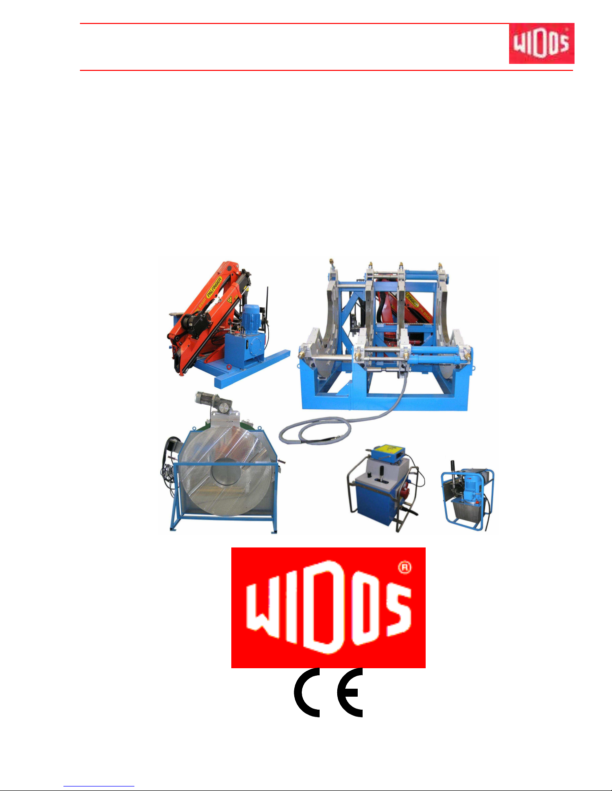
Heating element butt welding machine
WIDOS 20000
Keep for further use!
Page 2

Kunststoff schweißtechnik
Product identification
16.01.12 Working Instructions WIDOS 20000 Page 2 of 98
Model: Heating element butt welding machine
Type:
WIDOS 20000
Serial number, year of construction: see type label
Customer Entries
Inventory-No.:
Place of working:
Order of spare parts and after sales service:
Address of manufacturer
WIDOS
W. Dommer Söhne GmbH
Einsteinstrasse 5
D-71254 Ditzingen-Heimerdingen
Phone: ++49 7152 / 99 39 - 0
Address of the subsidiary companies:
WIDOS
WIDOS GmbH W. Dommer Söhne AG
An der Wiesenmühle 15 St. Gallerstr. 93
D-09224 Grüna / Sachsen CH – 9201 Gossau
Phone: ++49 371 / 8 15 73 - 0 Phone: ++41 71 / 388 89 79
Fax: ++49 371 / 8 15 73 - 20 Fax: ++41 71 / 388 89 73
Page 3

Kunststoff schweißtechnik
Introduction
16.01.12 Working Instructions WIDOS 20000 Page 3 of 98
Purpose of the document
These working instructions give you information about all important questions which refer to
the construction and the safe working of your machine.
Just as we are, you are obliged to engage in these working instructions, as well.
Not only to run your machine economically but also to avoid damages and injuries.
Should questions arise, contact our service team in the factory or in our subsidiary companies.
We will help you with pleasure.
According to our interest to continuously improve our products and working instructions, we
kindly ask you to inform us about problems and defects which occur in exercise.
Thank you.
Structure of the working instructions
This manual is arranged in chapters, which belong to the different using phases of the
machine.
Due to this structure, the searched information can be easily found.
1/16/2012 WIDOS
W. Dommer Söhne GmbH
Einsteinstraße 5
D-71254 Ditzingen-Heimerdingen
All rights reserved.
Reprinting only allowed with permission of the corporation.
Any changes are subject to technical innovations.
Page 4

Kunststoff schweißtechnik
Contents
16.01.12 Working Instructions WIDOS 20000 Page 4 of 98
1. DESCRIPTION OF THE PRODUCT .............................................................................. 7
1.1. Usage and purpose-oriented use ........................................................................................7
1.2. Safety measures....................................................................................................................7
1.3. Conformity .............................................................................................................................7
1.4. Machine overview .................................................................................................................8
1.5. Designation of the product ..................................................................................................8
1.5.1. Technical data ....................................................................................................................8
1.5.1.1. WIDOS 20000 General data .....................................................................................9
1.5.1.2. Basic frame ................................................................................................................9
1.5.1.3. Hydraulic aggregate enclosed for welding (optional) .................................................9
1.5.1.4. Hydraulic aggregate naked for welding (optional)....................................................10
1.5.1.5. General date for crane (optional) .............................................................................10
1.5.1.6. Hydraulic aggregate for crane (optional)..................................................................10
1.5.1.7. Heating element.......................................................................................................11
1.5.1.8. Planer.......................................................................................................................11
1.5.1.9. Reception box (optional) ..........................................................................................11
1.6. Accessories .........................................................................................................................11
2. SAFETY RULES .......................................................................................................... 12
2.1. Explanation of the symbols and indications....................................................................12
2.2. Obligations of the owner....................................................................................................13
2.3. Obligations of the worker...................................................................................................13
2.4. Measures of organization...................................................................................................13
2.5. Information about safety precautions...............................................................................13
2.6. Instructions for the staff.....................................................................................................13
2.7. Maintenance and inspection, repair..................................................................................14
2.8. Dangers while handling the machine................................................................................14
2.9. Dangers caused by electric energy...................................................................................14
2.10. Specific dangers .................................................................................................................14
2.10.1. Danger of stumbling over electric / hydraulic wires ..........................................................14
2.10.2. Dangers caused by the hydraulics....................................................................................15
2.10.3. Danger of combustion by heating element, reception box and welding area...................15
2.10.4. Danger of crushing at clamping tools and guide rails.......................................................15
2.10.5. Danger of catching clothes by the planer .........................................................................16
2.10.6. Risk of injury by noise.......................................................................................................16
2.11. Structural modifications on the machine .........................................................................16
2.12. Warranty and liability..........................................................................................................16
3. FUNCTIONAL DESCRIPTION..................................................................................... 17
4. OPERATING AND INDICATING ELEMENTS.............................................................. 18
4.1. Basic machine .....................................................................................................................18
4.2. Hydraulic aggregate, enclosed, for welding (optional) ...................................................19
4.3. Weld log recording apparatus SPA 600 (optional) ..........................................................21
Page 5

Kunststoff schweißtechnik
Contents
16.01.12 Working Instructions WIDOS 20000 Page 5 of 98
4.4. Hydraulic aggregate, naked, for welding (optional) ........................................................22
4.5. Heating element ..................................................................................................................23
4.6. Planer ...................................................................................................................................24
4.6.1. Protective motor switch at the planer................................................................................25
4.7. Crane (optional)...................................................................................................................26
5. STARTING AND OPERATING..................................................................................... 27
5.1. Safety indications ...............................................................................................................27
5.2. How to install the base frame ............................................................................................28
5.3. Lifting crane.........................................................................................................................29
5.4. How to operate the crane ...................................................................................................30
5.5. How to connect the machine with the naked hydraulic aggregate (optional) ..............31
5.6. How to connect the machine with the enclosed hydraulic aggregate (optional) .........31
5.7. How to set the heating element temperature ...................................................................32
6. WELDING PROCESS WITH SPA 600......................................................................... 33
6.1. Connect the SPA 600 to the hydraulic aggregate............................................................33
6.2. Description of the display ..................................................................................................34
6.3. Programming of the SPA 600.............................................................................................35
6.3.1. Selection of the pipe data .................................................................................................36
6.3.2. Setting menu.....................................................................................................................37
6.3.2.1. Parameter menu / Laboratory menu ........................................................................39
6.4. Welding process .................................................................................................................41
6.4.1. How to insert the pipes .....................................................................................................41
6.4.2. Drag pressure measurement ............................................................................................41
6.4.3. Dimension.........................................................................................................................42
6.4.4. Weather / protection .........................................................................................................43
6.4.5. Planing..............................................................................................................................43
6.4.6. Compensation of mismatch ..............................................................................................44
6.4.7. Bead up.............................................................................................................................44
6.4.8. Heating up.........................................................................................................................45
6.4.9. Change over .....................................................................................................................45
6.4.10. Pressure ramp ..................................................................................................................46
6.4.11. Joining and cooling ...........................................................................................................46
6.4.12. Completion of welding ......................................................................................................46
6.4.13. Signification of the error codes .........................................................................................47
6.4.14. Copying the internal data on SD - card and deleting internal data (RAM)........................47
6.5. SD card and drive................................................................................................................48
6.6. Bar code reading pen (optional)........................................................................................48
6.7. How to read out WICON with USB card reader (optional) ..............................................49
6.8. How to read the welding data ............................................................................................49
6.9. Diagnosis program .............................................................................................................49
7. WELDING PROCESS WITHOUT SPA ........................................................................ 51
Page 6

Kunststoff schweißtechnik
Contents
16.01.12 Working Instructions WIDOS 20000 Page 6 of 98
8. WELDING LOG AND TABLES.................................................................................... 54
9. MAINTENANCE, CARE AND REPAIR ........................................................................ 57
9.1. Maintenance and inspection, repair..................................................................................57
9.2. Storage.................................................................................................................................58
9.3. Clamping elements .............................................................................................................58
9.4. How to clean the machine..................................................................................................58
9.5. How to check the hydraulic oil level for welding .............................................................58
9.6. How to check the hydraulic oil level / refilling .................................................................59
9.7. Used hydraulic oil ...............................................................................................................59
9.8. How to lubricate the guide rods ........................................................................................59
9.9. How to vent the hydraulic cylinders .................................................................................60
9.10. Planer ...................................................................................................................................61
9.11. Protect machine parts against corrosion .........................................................................61
9.12. Disposal ...............................................................................................................................61
10. TRANSPORT ............................................................................................................... 62
11. HYDRAULIC AND ELECTRIC DIAGRAMS ................................................................. 63
11.1. Electric diagram with enclosed hydraulic aggregate ......................................................63
11.2. Electric diagram with naked hydraulic aggregate ...........................................................72
11.3. Hydraulic diagram for welding aggregates ......................................................................80
11.4. Hydraulic diagram for crane aggregat:.............................................................................80
12. SPARE PARTS LIST ................................................................................................... 81
12.1. Basic machine .....................................................................................................................81
12.2. Heating element ..................................................................................................................83
12.3. Planer ...................................................................................................................................85
12.4. Hydraulic aggregate, enclosed (optional) ........................................................................87
12.5. SPA-600................................................................................................................................89
12.6. Hydraulic aggregate, naked (optional)..............................................................................92
12.7. Protection box .....................................................................................................................94
12.8. Assembly frame for crane (optional).................................................................................96
13. DECLARATION OF CONFORMITY............................................................................. 98
Page 7

Kunststoff schweißtechnik
WIDOS Einsteinstr. 5 Phone ++49 7152 9939 - 0
W. Dommer Söhne GmbH D-71254 Ditzingen-Heimerdingen Fax ++49 7152 9939 - 40
website: www.widos.de email: [email protected]
16.01.12 Working Instructions WIDOS 20000 Page 7 of 98
1. Description of the product
This chapter gives important basic information about the product and its prescribed use.
All technical details of the machine are put together as a general arrangement.
1.1. Usage and purpose-oriented use
The WIDOS 20000 has been designed for the heating element butt welding of pipes and
fittings with a diameter range from Ø 1200 mm up to Ø = 2000 mm.
It is a machine for construction sites and particularly designed for the usage on-site, as well as
in the workshop.
For this reason, the frame is kept small so that it can be used even under difficult conditions
(e.g. ditch).
All use going beyond is not purpose-oriented.
The manufacturer is not responsible for damages caused by misuse.
The risk is held only by the user.
Also part of the purpose oriented use is
• respecting all the indications of the working instructions and
• performing the inspection and maintenance work.
1.2. Safety measures
In case of wrong use, wrong operation or wrong maintenance, the machine itself or products
standing nearby can be damaged or destroyed.
Persons being in the endangered area may be injured.
Therefore these working instructions have to be thoroughly read and the corresponding safety
regulations must be necessarily adhered to.
1.3. Conformity
The machine corresponds in its construction to the valid recommendations of the
European Community as well as to the according European standard specifications.
The development, manufacturing and mounting of the machine were made very
carefully.
Page 8
Kunststoff schweißtechnik
Description of the product Chapter 1
16.01.12 Working Instructions WIDOS 20000 Page 8 of 98
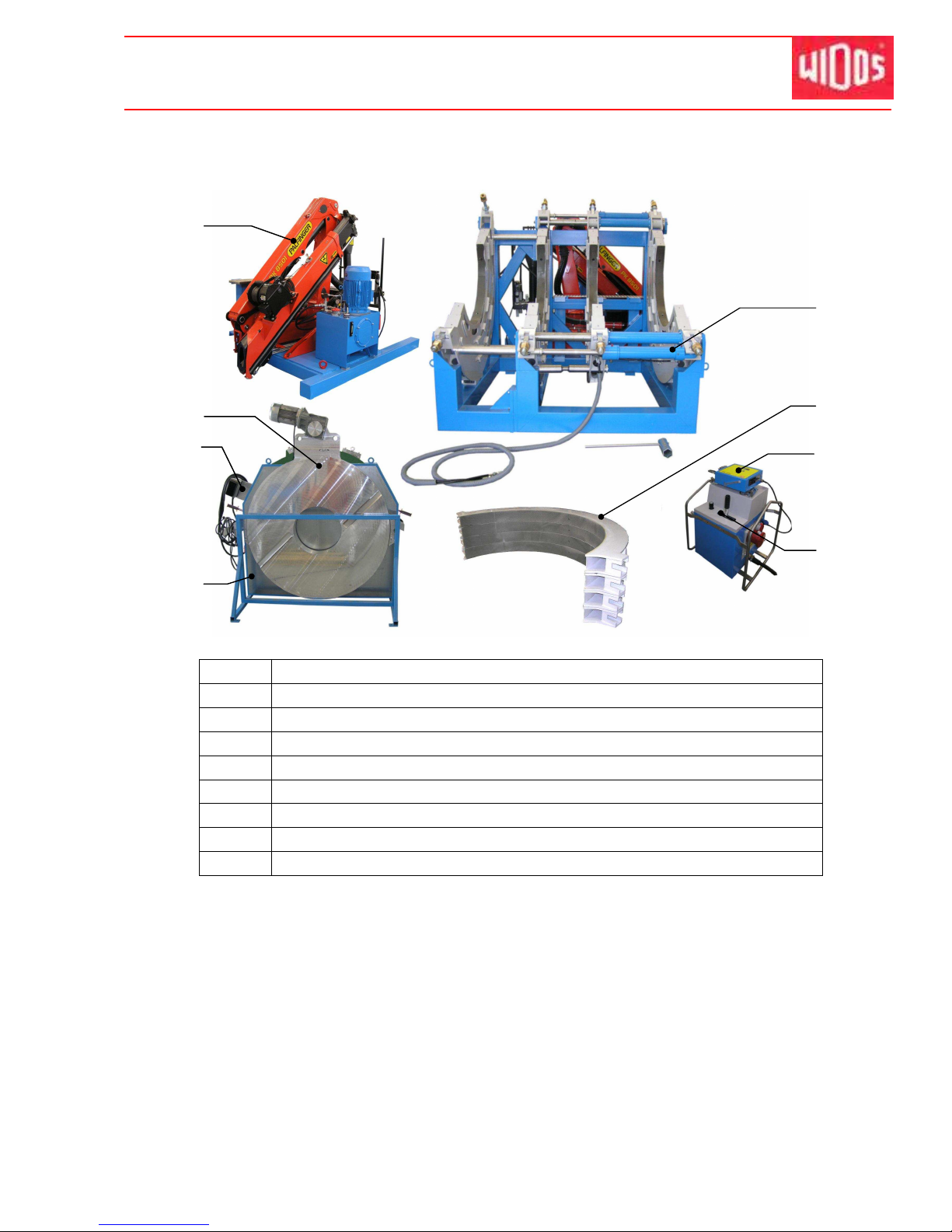
1.4. Machine overview
1 Crane (optional)
2 Planer
3 Heating element
4 Reception box
5 Basic machine
6 clamping devices, upper part
7 SPA (optional)
8 Hydraulic aggregate enclosed (optional)
- Hydraulic aggregate naked (optional)
1.5. Designation of the product
The product is designated by type labels which are attached at the crane, at the aggregate, at
the heating element, at the planer and at the basic machine.
They contain the type, the serial number and the year of construction of the machine.
1.5.1. Technical data
All important technical data of each single component are displayed.
They allow a rapid information about the working capacity and the structure.
1
2
3
4
5
6
7
8
Page 9
Kunststoff schweißtechnik
Description of the product Chapter 1
16.01.12 Working Instructions WIDOS 20000 Page 9 of 98
1.5.1.1. WIDOS 20000 General data
Pipe diameter range:
∅∅∅∅
outside
1200 - 2000 mm
Material which can be welded: PP, PE 80, PE 100
Weight (without accessories): appr. 10800 kg
Emissions - Noise exceeding 80 dB (A) may occur; during
planing it is obligatory to wear ear protection!
- When using the named pipe materials and when welding
below 260°C no toxicant damp arises
Ambient conditions in the
welding area:
- take care for cleanness (no dust at the welding area)
- If secured by an appropriate measurement that allowed
conditions for welding are indicated, it is possible to work
in any outside temperature condition as far as the welder
is not constrained in its manual skill.
- Avoid humidity, if necessary use a welding tent
- avoid strong sun rays influence
- protect from wind, shut pipe ends
1.5.1.2. Basic frame
Material frame: Structural steel
Material reduction inserts: Steel
∅ cylinder / ∅ piston rod: 80 mm / 50 mm
Stroke length of cylinder: 500 mm
Max. force (F=P*A):
61,3 kN (at p= 100 bar)
153,25 kN (at p= 250 bar)
Weight appr.2000 kg
1.5.1.3. Hydraulic aggregate enclosed for welding (optional)
Power: 2,6 / 3,1 kW
Voltage: 400 V (+-10%)
Current 5, 5 / 7, 6 A (± 10 %)
Feeding CEE 125 A – phase converter
Frequency: 50 Hz
Hydraulic oil tank: appr. 10 L
Insulation system IP 54
Electromotor and pump:
Speed: 1450 rpm
Max. working pressure of pump: appr. 250 bar
Working pressure: 0-250 bar adjustable
Weight: appr. 56 kg
Page 10
Kunststoff schweißtechnik
Description of the product Chapter 1
16.01.12 Working Instructions WIDOS 20000 Page 10 of 98
1.5.1.4. Hydraulic aggregate naked for welding (optional)
Power: 2,6 / 3,1 kW
Voltage: 400 V (+-10%)
Current 5, 5 / 7, 6 A (± 10 %)
Feeding CEE 16 A – phase converter
Frequency: 50 Hz
Hydraulic oil tank: appr. 10 L
Insulation system IP 54
Electromotor and pump:
Speed: 1450 rpm
Max. working pressure of pump: appr. 160 bar
Working pressure: 0-160 bar adjustable
Weight: appr. 45 kg
1.5.1.5. General date for crane (optional)
Power: 18,0 kW
Voltage: 400 V (+-10%)
Feeding CEE 63 A – phase converter
Frequency: 50 Hz
1.5.1.6. Hydraulic aggregate for crane (optional)
Power: 15 kW
Voltage: 400 V (+-10%)
Current 27,28 / 15,71 A (± 10 %)
Hydraulic oil tank: appr. 100 l
Insulation system IP 55
Electromotor and pump:
Speed: 1445 rpm
Max. working pressure of pump: appr. 250 bar
Working pressure: 0-250 bar adjustable
Weight: appr. 190 kg
Page 11
Kunststoff schweißtechnik
Description of the product Chapter 1
16.01.12 Working Instructions WIDOS 20000 Page 11 of 98
1.5.1.7. Heating element
Power: 42 kW
Voltage: 400V (+-10%)
Current: 182 A (+-10%)
Frequency: 50 Hz
Outside-∅: 2180 mm
Inside-Ø: 900 mm
Surface: non-stick-coated
Attached elements: - Electronic temperature control
- Fuse for temperature control
- On/off-switch with control lamp,
- Connecting cable with CEE – plug (125A)
Weight: appr. 500 kg
1.5.1.8. Planer
Motor: Three-phase alternating current motor
Power: 4,0 kW
Voltage: 400 V (+-10%)
Nominal current 8,4 A
Frequency: 50 Hz (+-10%)
Speed: appr. 4,2 rpm
Attached elements: CEE 16A – motor protective
Weight: appr. 1100 Kg
1.5.1.9. Reception box (optional)
Dimension: appr. 2400 x 1500 x 2100 mm
Weight: appr. 500 kg
1.6. Accessories
Following tools and accessories are part of the delivery:
1 Tool bag for 10 parts
1 hexagonal socket screw key angle, size 4 / 5 / 14
1 each Spanner wrench size 13 / 19 / 24 / 30
1 Torx-Screw driver T10
1 Socket spanner size 65
1 Wire rope with hook (J9994)
Page 12
Kunststoff schweißtechnik
WIDOS Einsteinstr. 5 Phone ++49 7152 9939 - 0
W. Dommer Söhne GmbH D-71254 Ditzingen-Heimerdingen Fax ++49 7152 9939 - 40
website: www.widos.de email: [email protected]
16.01.12 Working Instructions WIDOS 20000 Page 12 of 98
2. Safety rules
The base for the safe handling and the fault-free operation of this machine is the knowledge of
the basic safety indications and rules.
• These working instructions contain the most important indications to run the machine
safely.
• The safety indications are to be followed by all persons working on the machine.
2.1. Explanation of the symbols and indications
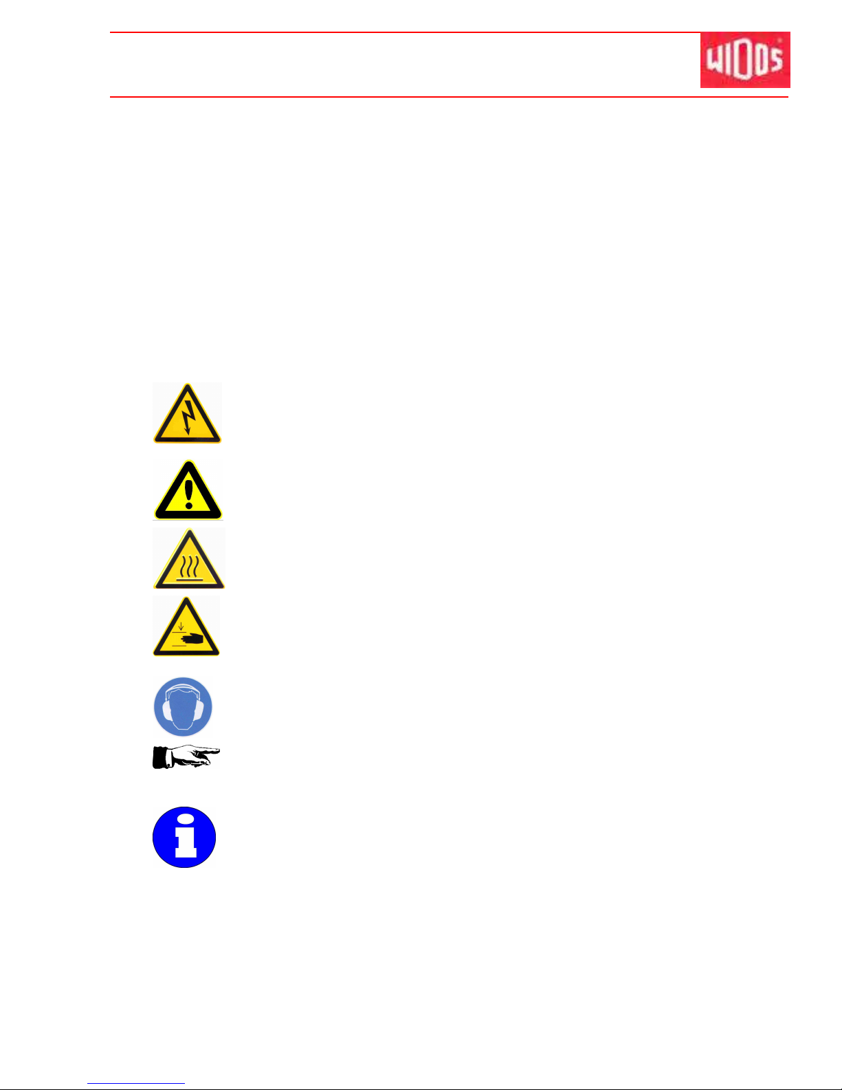
In the working instructions, following denominations and signs are used for dangers:
This symbol means a possibly danger for the life and the health of persons.
• The disrespect of these indications may have heavy consequences for the
health.
This symbol means a possible dangerous situation.
• The disrespect of these indications may cause slight injuries or damages on
goods.
This symbol means a possible dangerous situation due to hot surfaces.
• The disrespect of these indications may conduct to heavy burns, respectively
to self-ignition or even fire.
This symbol means a possible dangerous situation by moving parts of the
machine
• The disrespect of these indications may cause heavy crushing’s of parts of the
body resp. damages of parts of the machine.
This symbol means a possible risk of injury by noise exceeding 80 dB (A).
• Ear protection is obligatory
This symbol gives important indications for the proper use of the machine.
• The disrespect of these indications may conduct to malfunctions and
damages on the machine or on goods in the surrounding.
Under this symbol you get user tips and particularly useful information.
• It is a help for using all the functions on your machine in an optimal way and
helps you to make the job easier.
The regulations for the prevention of accidents are valid (UVV).
Page 13

Kunststoff schweißtechnik
Safety rules Chapter 2
16.01.12 Working Instructions WIDOS 20000 Page 13 of 98
2.2. Obligations of the owner
The owner is obliged only to let persons work at the machine, who
• know about basic safety and accident prevention rules and are instructed in the handling of
the machine, as well as who
• have read and understood the safety chapter of this manual and certify this by their
signature.
The safety-conscious working of the staff has to be checked in regular intervals.
2.3. Obligations of the worker
All persons who are to work at the machine are obliged before working:
• To follow the basic safety and accident protection rules.
• To have read and understood the safety chapter and the warnings in this manual and to
confirm by their signature that they have well understood them.
• To inform themselves about the functions of the machine before using it.
2.4. Measures of organization
• All equipment required for personal safety is to be provided by the owner.
• All available safety equipment is to be inspected regularly.
2.5. Information about safety precautions
• The working instructions have to be permanently kept at the place of use of the machine.
They are to be at the operator's disposal at any time and without effort.
• In addition to the manual, the common valid and the local accident protection rules and
regulations for the environmental protection must be available and followed.
• All safety and danger indications on the machine have to be in a clear readable condition.
• Every time the machine changes hands or is being rent to third persons, the working
instructions are to be sent along with and their importance is to be emphasized.
2.6. Instructions for the staff
• Only skilled and trained persons are allowed to work at the machine.
• It must be clearly defined who is responsible for transport, mounting and dismounting,
starting the operation, setting and tooling, operation, maintenance and inspection, repair
and dismounting.
• A person who is being trained may only work at the machine under supervision of an
experienced person.
Page 14
Kunststoff schweißtechnik
Safety rules Chapter 2
16.01.12 Working Instructions WIDOS 20000 Page 14 of 98
2.7. Maintenance and inspection, repair
All maintenance and repair work have to be basically performed with the
machine in off position.
During this, the machine has to be secured against unauthorized switching on.
Prescribed maintenance and inspection work should be performed in time.
The DVS gives the advice of inspection work after 1 year.
For machines with an especially high usage percentage the testing cycle should
be shortened.
The work should be performed at the WIDOS GmbH company or by an
authorized partner.
2.8. Dangers while handling the machine
The machine WIDOS 20000 is constructed according to the latest technical standard and the
acknowledged technical safety rules. However, dangers for the operator or other persons
standing nearby may occur. Also material damages are possible.
The machine may only be used:
• according to the purpose-oriented usage
• in safety technical impeccable status
Disturbances, which may affect the safety of the machine, must be cleared immediately.
2.9. Dangers caused by electric energy
Only skilled persons are allowed to work at electrical appliances!
The electrical equipment of the machine has to be checked regularly. Loose
connections and damaged cables have to be replaced immediately.
• If work at alive parts are necessary, a second person has to assist who can disconnect the
machine from the mains if necessary.
• All electric tools (heating element, planer and aggregate) have to be protected from rain
and dropping water (if need be use a welding tent).
• According to VDE 0100, the use on construction sites is only allowed with a power
distributor with a FI-safety switch.
2.10. Specific dangers
2.10.1. Danger of stumbling over electric / hydraulic wires
Make sure that no person has to step over the wires.
Lay the wires in such a way that the danger is kept to a minimum.
Do not kink or crush the lines.
Page 15
Kunststoff schweißtechnik
Safety rules Chapter 2
16.01.12 Working Instructions WIDOS 20000 Page 15 of 98
2.10.2. Dangers caused by the hydraulics
System parts and pressure hoses should be depressurized before beginning of
any repair work. Even if the machine is switched off, pressure may be in the
hydraulic accumulator!
There is a danger of injuring the eyes by hydraulic oil squirting out.
• Damaged hydraulic hoses have to be immediately replaced.
• Make a visual inspection of the hydraulic hoses before each work beginning.
• The hydraulic oil is inedible!
2.10.3. Danger of combustion by heating element, reception box and
welding area
You can burn yourself, inflammable materials can be ignited.
The heating element temperature is heated up to more than 250°C!
• Do not leave the heating element unsupervised.
• Do not touch the surfaces of the heating element.
• Take enough safety distance to inflammable materials.
• Do wear safety gloves.
• Make sure that no person is in the lifting area of the heating element.
• When cleaning the hot heating element with detergents (e.g. with PE cleaner) there is the
danger of inflammation. For this reason, please take care that the inflammation point is
above the actual temperature of the heating element. Do not approach it with any fire
sources (e.g. cigarettes).
2.10.4. Danger of crushing at clamping tools and guide rails
Heavy injuries can result from crushing:
- Upon opening / closing the clamping tools.
- Upon inserting the planer and heating element.
- Upon opening / closing the machine.
- Upon mounting the reducer inserts.
- Upon clamping the pipes.
- On the one hand between the inner clamping rings, on the other hand
between the outer clamping rings and the end of the guiding shaft.
• Do not stand or put your hands between the inner clamping tools with not yet clamped
pipes and between the end of the guiding shaft.
• Do not reach between the clamping rings in case the pipes are yet to be clamped and in
case you move the clamping tools.
• During the installation of the reducer inserts use a lifting device, do not reach between
reducer insert and clamping tool.
• Do not block the opening and closing of the machine carriages.
Page 16
Kunststoff schweißtechnik
Safety rules Chapter 2
16.01.12 Working Instructions WIDOS 20000 Page 16 of 98
2.10.5. Danger of catching clothes by the planer
You can cut yourself or even get bones broken!
For some machines, the planer may shortly turn when switching the machine
on!
• Only wear clothes tight to the body.
• Do not wear rings or jewelry during the work.
• If necessary, wear a hair-net.
• Make sure that no person is in the lifting area of the planer.
• Do not reach or step between the clamped pipes
• Always put the planer back into the reception box after and before each use.
• Transport the planer at the suspension only and hold ist only at the grips. Do not touch the
surfaces.
2.10.6. Risk of injury by noise
Noise exceeding 80 dB (A) may occur; during planing it is obligatory to wear
ear protection!
2.11. Structural modifications on the machine
• No modifications, extensions or reconstructions may be made on the machine without
permission of the manufacturer.
• Machine parts which are not in a perfect condition are to be replaced immediately.
• Only use original WIDOS spare and wear parts.
• In case of purchase orders please always state the machine number!
2.12. Warranty and liability
Fundamentally our "General Sales and Delivery Conditions" are valid.
They are at the owner's disposal latest when signing the contract.
Guarantee and liability demands referring to personal injuries or damages on objects are
excluded if they are caused by one or several of the following reasons:
• not using the machine according to the prescriptions
• inexpert transport, mounting, starting, operating, and maintenance of the machine
• running the machine with defective or not orderly mounted safety appliances
• ignoring the information given in this manual
• structural modifications on the machine without permission
• unsatisfactory checking of parts of the machine, which are worn out
• repairs performed in an inexpert way
• In case of catastrophes and force majeure
Page 17

Kunststoff schweißtechnik
WIDOS Einsteinstr. 5 Phone ++49 7152 9939 - 0
W. Dommer Söhne GmbH D-71254 Ditzingen-Heimerdingen Fax ++49 7152 9939 - 40
16.01.12 working Instructions WIDOS 20000 page 17 of 98
3. Functional description
Bas i ca ll y, t he i nt erna t iona l a nd n at iona l p roce s s g ui deli n es are t o be
fol lo wed!
The plastic pipes are clamped in the clamping devices.
Then the front sides of the pipes are cut plane and parallel by means of the planer and the
misalignment of the pipes is checked.
The cleaned and heated heating element is inserted and the pipes are pressed against the
heating element under defined adjusting pressure. This process is called "adjusting".
After the prescribed bead height being reached, pressure is reduced, the heating time
begins. The function of this time is to heat up the pipe ends.
After expiration of the heating time, the slides are opened, the heating element is removed
quickly and the pipes are driven together again.
The time gap from the removal of the heating element to joining the pipes is called change
over time.
The pipes are joined under prescribed welding pressure and then cool down under pressure
(cooling time).
T h e w el d e d j o i n t c a n b e u nc l a m p e d , t h e w el d i n g p r o ce s s i s
f i n i s he d .
Heating element heats
the pipes up to welding
temperature
Finished welding with
internal and external
bead
Page 18
Kunststoff schweißtechnik
WIDOS Einsteinstr. 5 Phone ++49 7152 9939 - 0
W. Dommer Söhne GmbH D-71254 Ditzingen-Heimerdingen Fax ++49 7152 9939 - 40
16.01.12 working Instructions WIDOS 20000 page 18 of 98
4. Operating and indicating elements
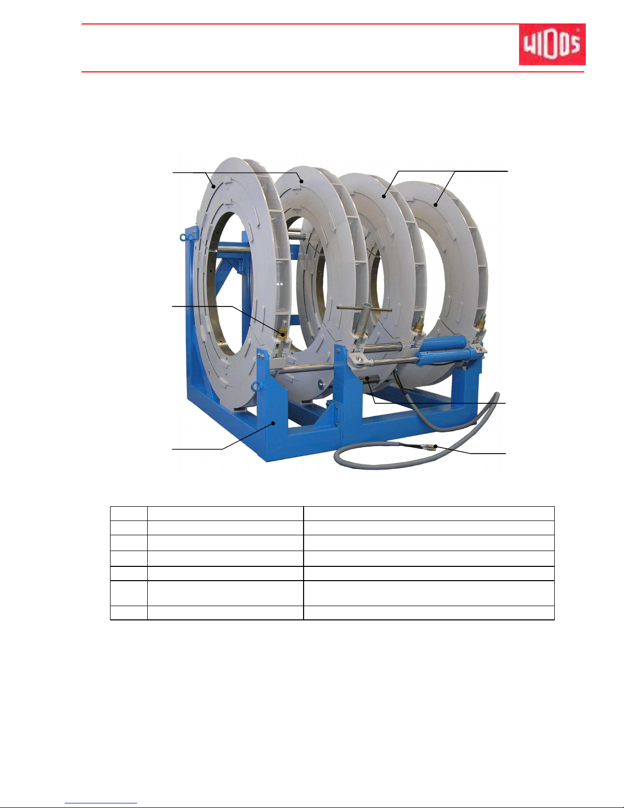
4.1. Basic machine
No. Name Function
1 Clamping ring fix to maintain the left clamped pipe
2 Spindle with clamping nut to clamp the pipes
3 Support may be disassembled if necessary
4 Clamping ring flexible to drive the right clamped pipe to and fro
5 Tear-off bar to separate the heating element from the pipe ends
after heating
6 Hydraulic hoses to connect with the hydraulic aggregate
1
2
3
4
5
6
Page 19
Kunststoff schweißtechnik
Operating and indicating elements Chapter 4
16.01.12 Working Instructions WIDOS 20000 Page 19 of 98
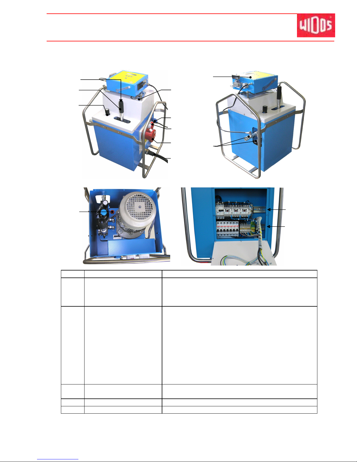
4.2. Hydraulic aggregate, enclosed, for welding (optional)
No. Name Function
7 Push-button - By pressing the push-button, the motor switches over
to high speed
- Without pressing the button, the motor drives with
normal speed
8 Valve lever To open the slides. There are 4 different positions:
- To the left side: slides close.
- in the middle (usual position): the pressure which is
currently achieved is kept (also by means of the
built-in hydraulic accumulator)
- slightly to the right side (depressurized position):
a possibly existing pressure is released without
Moving the slides. Due to the hydraulic accumulator,
It takes about 10 s until the pressure is completely
released.
- to the right side: slides open
9 Setting screw for pressure
relief valve
Limitation of the pressure to the desired value.
10 Pressure gauge Display of the hydraulic pressure
11 Plug 230V / 16A Connection for SPA-600
7
8
9
10
11
12
13
14
17
F10 / Q1 /
Q3 / Q2
F1 / F2 / F3
16
15
Page 20
Kunststoff schweißtechnik
Operating and indicating elements Chapter 4
16.01.12 Working Instructions WIDOS 20000 Page 20 of 98
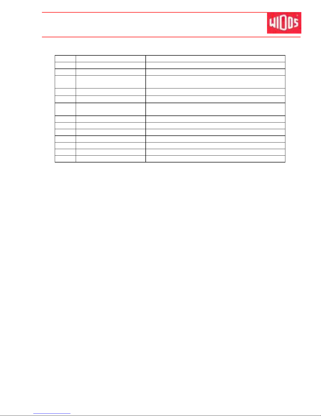
No. Name Function
12 Plug CEKON 16A Connection for planer
13 Plug CEKON 125A Connection for heating element
14 Connecting cable with plug
CEE 125 A
Connection to local power supply
15
SPA 600 The weldings are registered and logged
16
Plug-in couplings Connection for hydraulic hoses of the basic machine
17 Screw with oil dipstick Checking the oil level
Oil filler neck
F10 Motor protective Hydraulic pump 7,6 – 10 A
Q1 Contactor - Speed slow
Q3 Contactor - Speed fast 2
Q2 Contactor - Speed fast 1
F1 Circuit breaker - Fuse hydraulic pump 3x B16A
F2 Circuit breaker (3 pieces) - Fuse planer 3x K16A
F3 Circuit breaker (3 pieces) - Fuse plug socket SPA B16A
The fuses are mounted on the right side of the aggregate behind the power sockets.
In case a fuse has been activated, thus:
• Eliminate the malfunction.
• Disconnect the aggregate from the mains afterwards.
• Detach the screws from the panel with the power sockets.
• Activate the fuse again.
• Mount the panel with the power sockets again.
• Reconnect the aggregate to the power supply.
Page 21
Kunststoff schweißtechnik
Operating and indicating elements Chapter 4
16.01.12 Working Instructions WIDOS 20000 Page 21 of 98
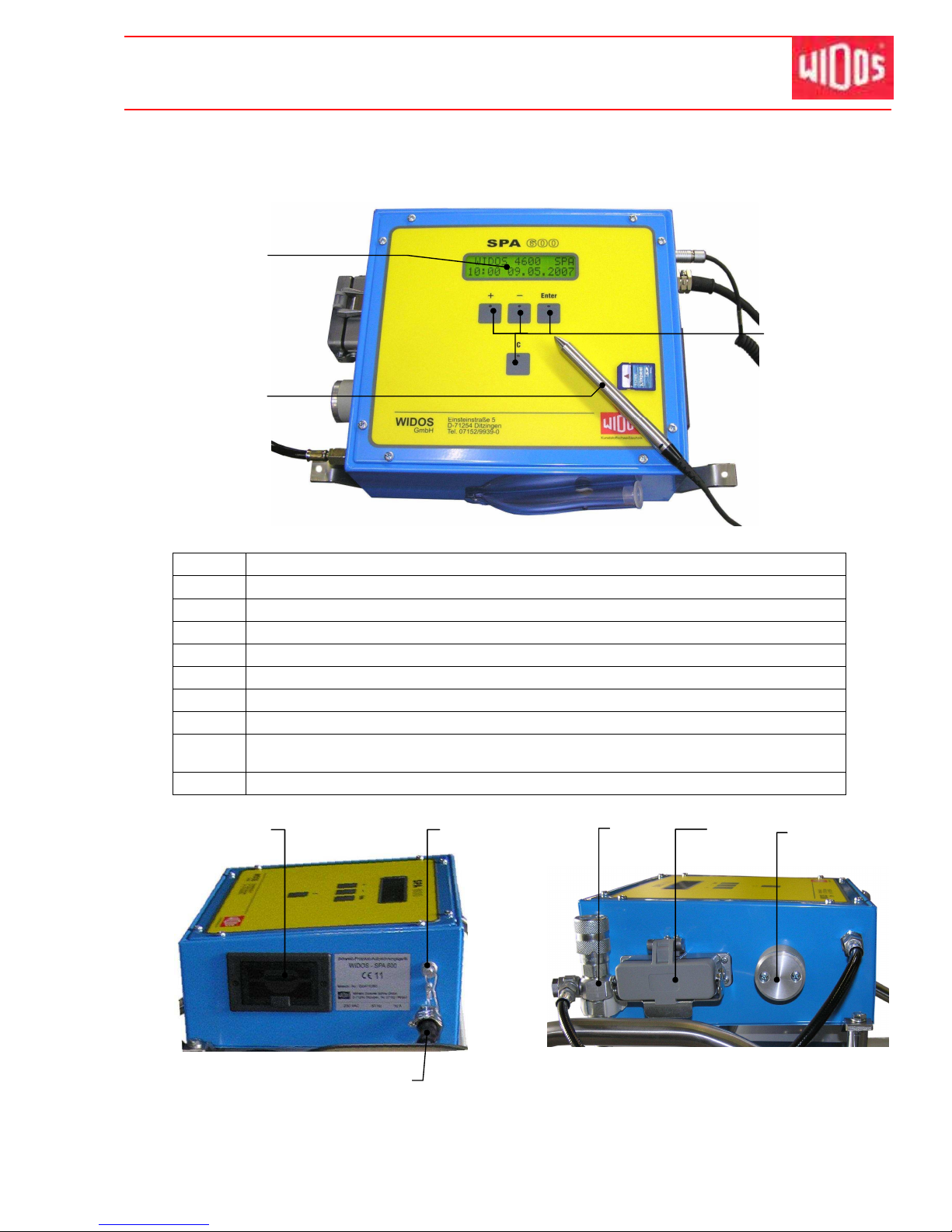
4.3. Weld log recording apparatus SPA 600 (optional)
No. Name
18 Display
19 Bar code-reading pen (optional)
20 Buttons for operation
21 Drive for the SD – card
22 Interface for barcode reading pen (optional)
23 Connecting cable
24 Holder for T-piece
25 - Plug box for the heating element (when 230 V)
- Plug box for heating element probe (when 400V)
26 Outside temperature probe
19
18
20
24
25
26
21
22
23
Page 22
Kunststoff schweißtechnik
Operating and indicating elements Chapter 4
16.01.12 Working Instructions WIDOS 20000 Page 22 of 98
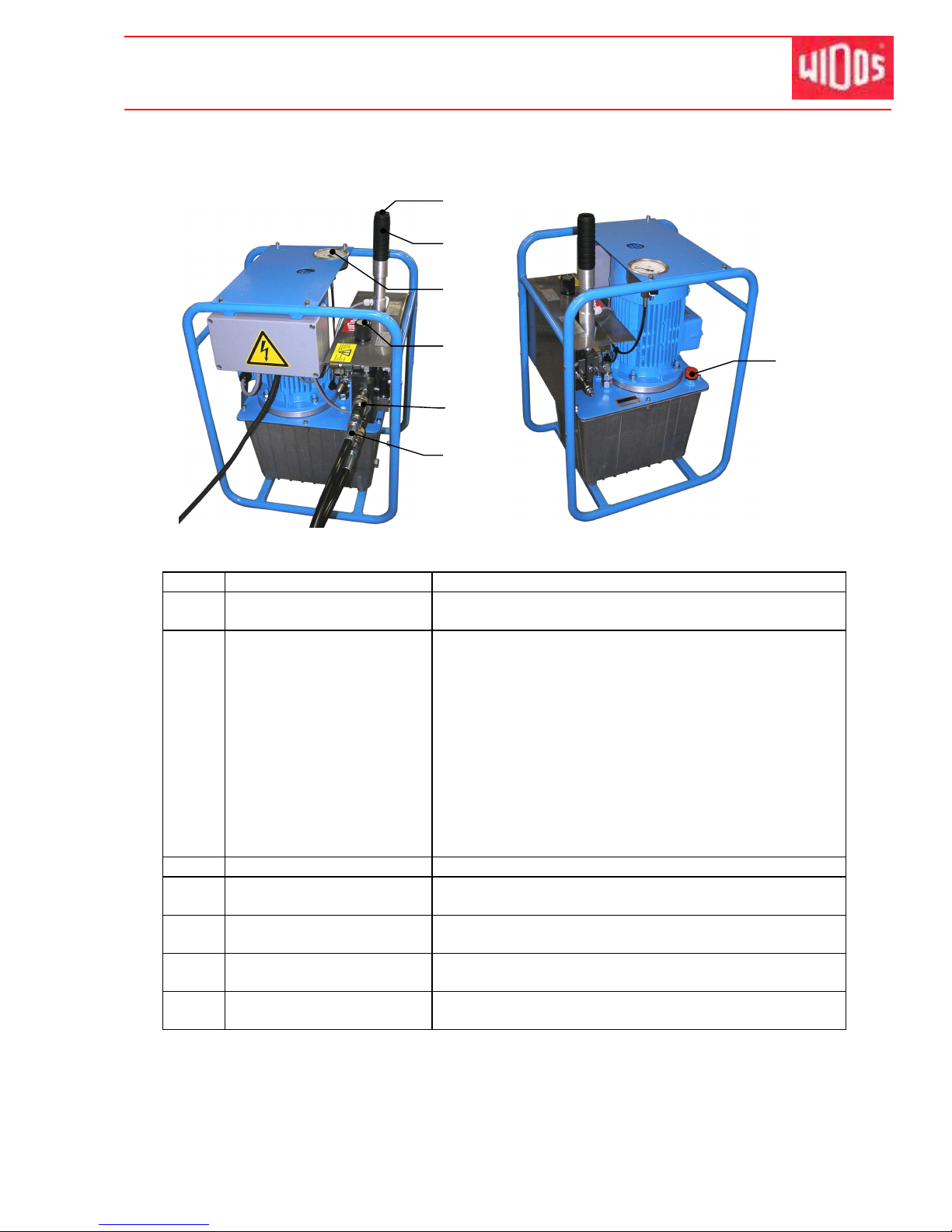
4.4. Hydraulic aggregate, naked, for welding (optional)
No. Name Function
27 Push-button By pressing the push-button the motor switches over to
high speed
28 Valve lever To open / close the slides. There are 4 different
positions:
- To the left side: slides close.
- in the middle (usual position): the pressure which is
currently achieved is kept (also by means of the
built-in hydraulic accumulator)
- slightly to the right side (depressurized position):
a possibly existing pressure is released without
Moving the slides. Due to the hydraulic accumulator,
It takes about 10 s until the pressure is completely
released.
- to the right side: slides open
29 Pressure gauge Display of the hydraulic pressure
30 Setting screw for pressure
relief valve
Limitation of the pressure to the desired value.
31 Hydraulic connection for
closing the slides
Non-dropping quick-action coupling
32 Hydraulic connection for
opening the slides
Non-dropping quick-action coupling
33 Screw with oil dipstick - Checking the oil level
- Oil filler neck
27
28
30
32
33
29
31
Page 23

Kunststoff schweißtechnik
Operating and indicating elements Chapter 4
16.01.12 Working Instructions WIDOS 20000 Page 23 of 98
4.5. Heating element
No. Name Function
34 Holder Possibility to hinge the heating element.
35 Grip To hold and adjust the heating element.
36 Visible type fuse Fuse protection for the regulator of temperature (2 A)
37 Connecting cable Power supply for heating element with CEE125A plug.
38
Connecting for
temperature sensor cable
Connection to SPA 600 (optional).
39 Thermostat To set the required temperature.
40 On / off switch with control
lamp red
To switch the heating element on / off.
w/o
image
Steel wire with hook To transport the heating element.
36
39
40
34
35
(35)
37
38
Page 24
Kunststoff schweißtechnik
Operating and indicating elements Chapter 4
16.01.12 Working Instructions WIDOS 20000 Page 24 of 98
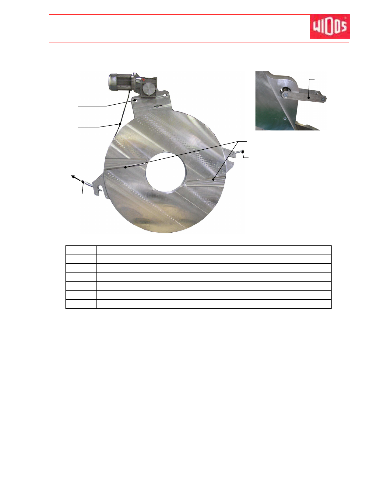
4.6. Planer
No. Name Function
41 Eye Possibility to hinge the planer
42 Connecting cable Power supply for planer with CEE16A plug
43 * Locking device To secure planer in the basic machine
44 Knife To make the pipe ends plane and parallel
45 Grab handle To hold and adjust the planer
46 Holder Possibility to hinge the planer
* Pull the rod with the ball knob in arrow direction in order to release the locking and to lift the
planer out of the base frame.
41
43
42
46
44
45
Page 25
Kunststoff schweißtechnik
Operating and indicating elements Chapter 4
16.01.12 Working Instructions WIDOS 20000 Page 25 of 98
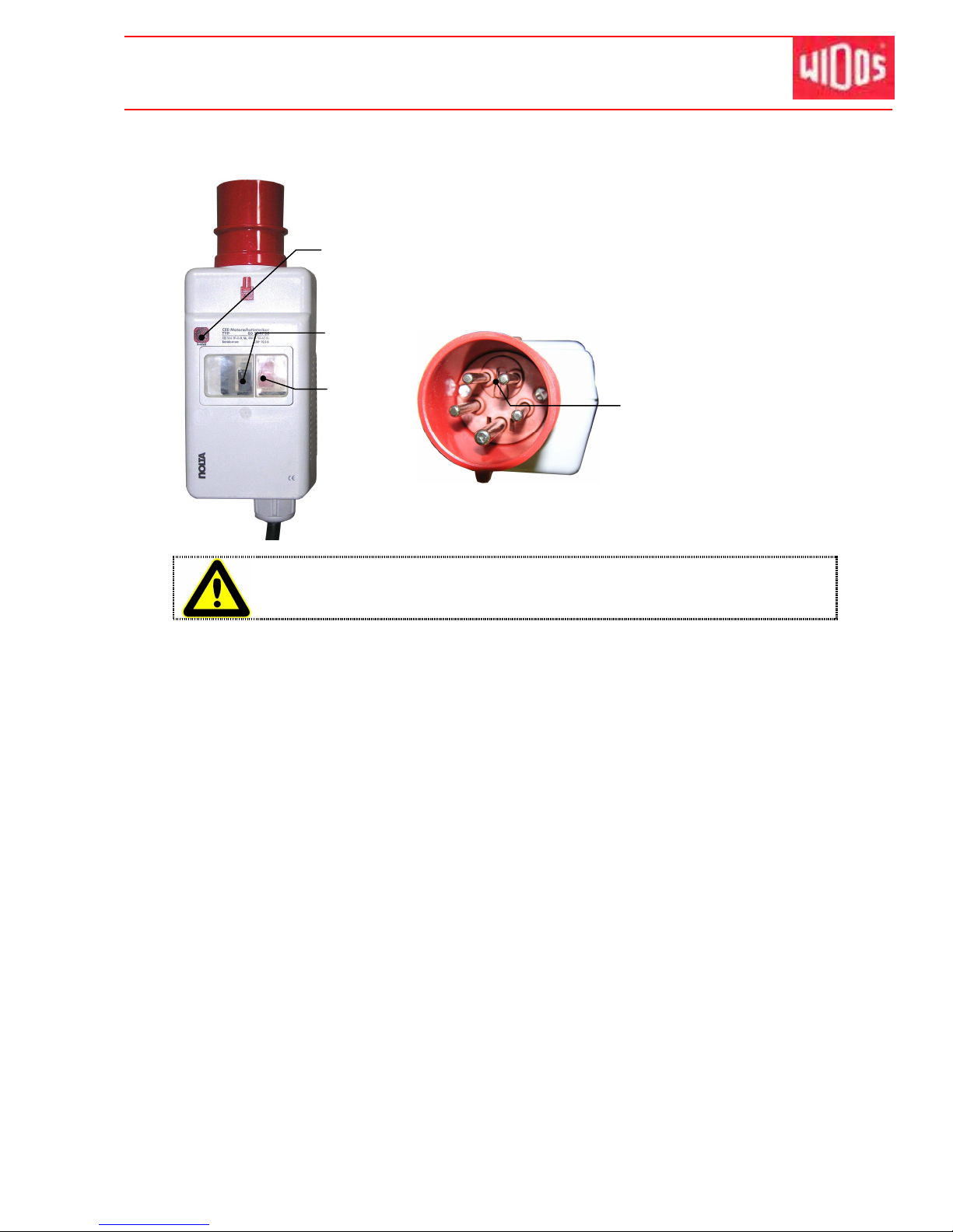
4.6.1. Protective motor switch at the planer
The planer is switched on/off at the protective motor switch.
The black switch starts the planer and the red one stops the
planer again.
The red button serves also as overload protection which
means that it switches the planer off automatically if the
pressure onto the planer is too high. In this case, release
pressure and start again the planer with the black button.
If the red control lamp lightens, the planer turns in the wrong direction.
Absolutely change the turning direction by turning the phase changing switch.
Control
lamp
OFF
ON
Phase changing switch
Page 26
Kunststoff schweißtechnik
Operating and indicating elements Chapter 4
16.01.12 Working Instructions WIDOS 20000 Page 26 of 98
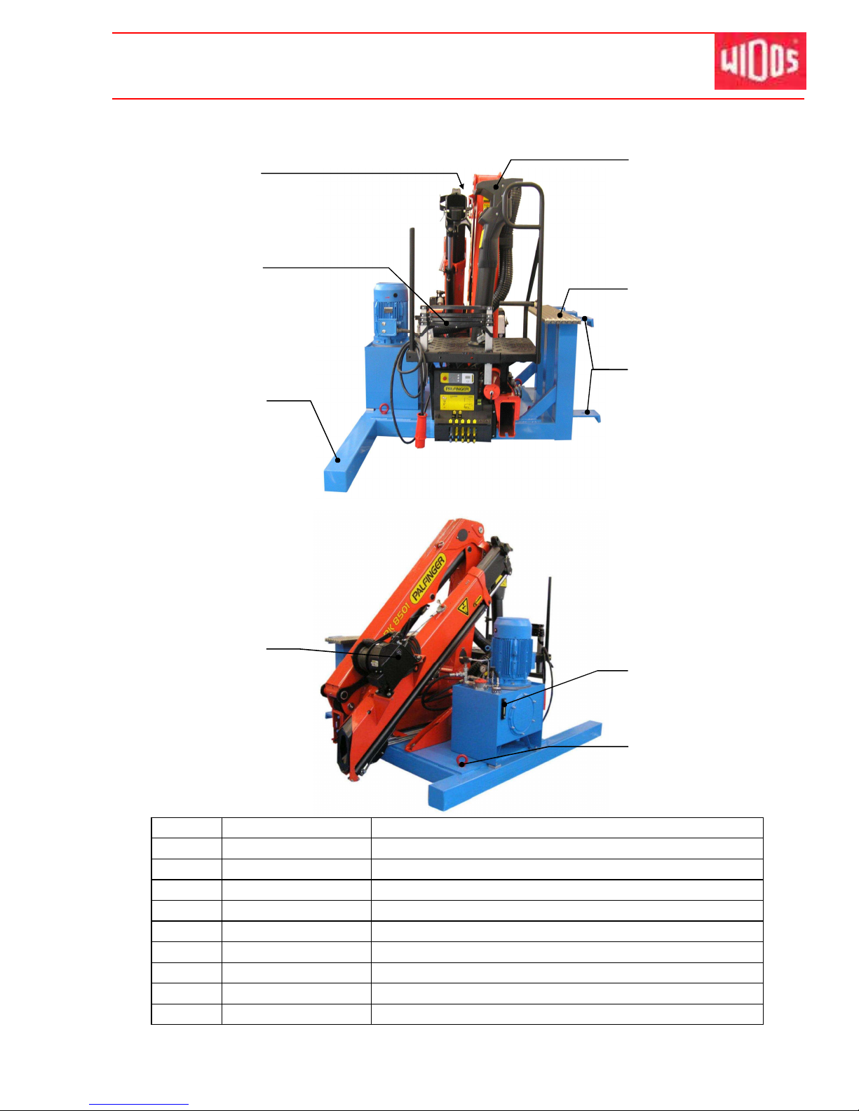
4.7. Crane (optional)
No. Name Function
47 Transport lock To lock the crane arm
48 Anti-drop device To secure the operator against falling
49 Frame Fixing for the single element
50 Operator console To operate the crane arm
51 Tread plate To hinge/unhinge planer and heating element
52 Fixing hook To fix the crane console to the base frame
53 Rope winch To roll up the rope with brake
54 Inspection glass To check the oil level
55 Ring bolt To transport
48
47
53
50
54
49
55
51
52
Page 27

Kunststoff schweißtechnik
WIDOS Einsteinstr. 5 Phone ++49 7152 9939 - 0
W. Dommer Söhne GmbH D-71254 Ditzingen-Heimerdingen Fax ++49 7152 9939 - 40
16.01.12 working Instructions WIDOS 20000 page 27 of 98
5. Starting and operating
The instructions of this chapter are supposed to initiate in the operation of the machine and
lead during the appropriate starting of the machine.
This includes:
- The safe operation of the machine
- using all the possible options of the machine
- economic operation of the machine
5.1. Safety indications
The machine may only be operated by initiated and authorized persons. For the
qualification, a plastic welding exam can be taken according to DVS and DVGW.
In situations of danger for persons and the machine, the mains plug has to be
unplugged immediately.
In case of power failure, there may still be pressure in the hydraulic system.
Therefore release pressure if need be.
After completion of the welding work and during breaks the machine has to be
switched off.
Further take care that no unauthorized person has access.
Protect the machine from wetness and humidity!
According to VDE 0100, the use on construction sites is only allowed with a
power distributor with a FI-security protective switch.
Check the oil level of the hydraulic system before each starting of the control
unit in order to avoid damages on the pump. The oil level must be between the
two marks at the oil dipstick.
If necessary add hydraulic oil of the quality HLPD 32.
The heating element surfaces must be clean, especially non greasy, therefore
they need to be cleaned shortly before each welding or in case of dirtiness by
means of a fiber-free paper and a cleaning agent (e.g. PE cleaner or pipe
cleaning cloths which are available at the WIDOS company).
Never discard the heating element unprotected onto its coated surfaces.
The anti-adhesive coating of the heating element must remain undamaged in
the working area.
Take care that all hydraulic and electric connections are connected.
Make sure that pumps and planer are connected in a way that they turn in righthanded direction otherwise change turning direction.
• Take into account the surrounding conditions:
- The welding may not be performed under direct sun rays influence.
- Use a welding umbrella if necessary.
• If the surrounding temperature is under 5°C, measures have to be taken:
- Use a welding tent or preheat the pipe ends if necessary.
In addition, take measures against rain, wind and dust.
Page 28
Kunststoff schweißtechnik
Starting and operating Chapter 5
16.01.12 Working Instructions WIDOS 20000 Page 28 of 98
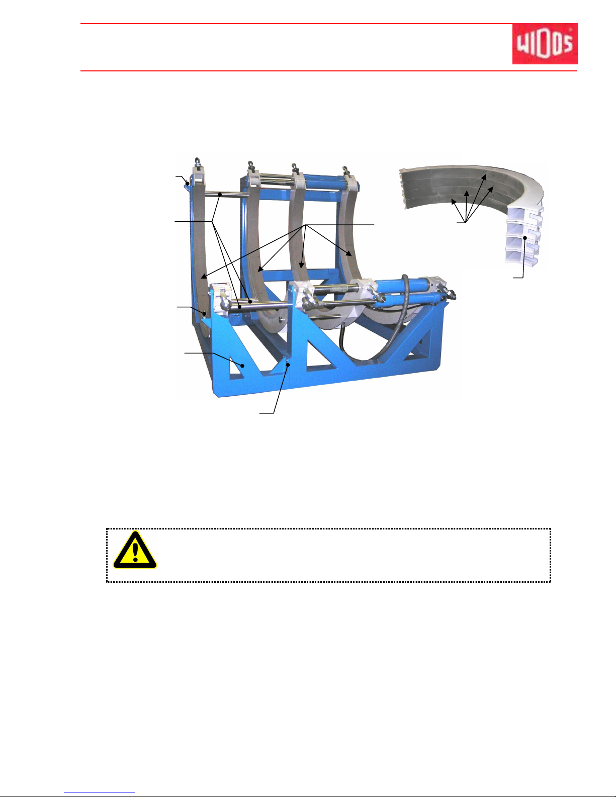
5.2. How to install the base frame
The base frame has been packed separately; the left clamping ring with support was
detached.
• Detach screws, lift up base frame by a lifting device and take base frame to its destination.
• Take up clamping ring with support at the ring screws, remove transport lugs and put
clamping ring with support next to the other base frame.
• Put all three spacer shafts into the drillings at both clamping rings and screw them each
from the outside by the cylinder head screw M20.
• Mount base frame and holder to each other by 12 Pan-head screws M20 + washers.
The clamping rings have been prepared with aliphatic rust-protective agent for
the transport.
• Necessarily degrease the inner surfaces prior to welding in order that correct
clamping is warranted.
Clamping ring
with support
Spacer shaft
Ring screw
Ring screw
Mount base
frame here
Degrease
clamping rings
Clamping
ring upper
parts
Page 29

Kunststoff schweißtechnik
Starting and operating Chapter 5
16.01.12 Working Instructions WIDOS 20000 Page 29 of 98
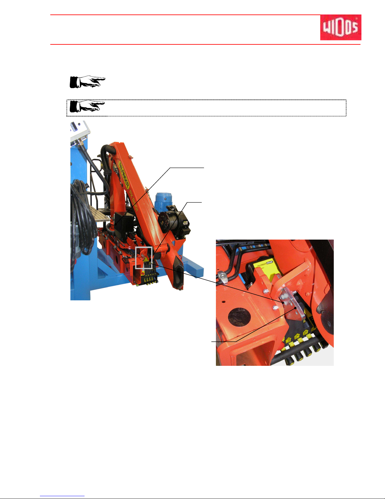
5.3. Lifting crane
The lifting crane has been fixed to a wooden floor by four screws.
• Remove the fixing screws and fix the four ring screws into the threaded drillings.
• Lift up the crane by a lifting device and put it behind the base frame.
• Fix the lifting crane to the base frame according to the image.
Fix ring screws here
Fixing screws to lift the
crane at the base frame
Page 30
Kunststoff schweißtechnik
Starting and operating Chapter 5
16.01.12 Working Instructions WIDOS 20000 Page 30 of 98
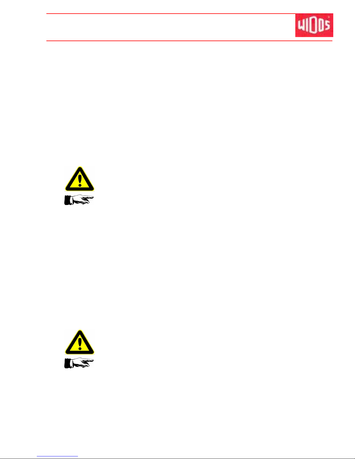
5.4. How to operate the crane
Necessarily read the working instructions of Palfinger Crane prior to the
first operation of the crane.
Make sure that the transport lock has been removed.
• If you want to work with the Palfinger crane, turn the crane button on: <1> and make sure
that the transport look has been removed.
• Please refer to the separately enclosed working instructions from Palfinger for operation
and maintenance.
Main switch
Detach the pan-head screw and necessarily
remove the transport lock.
Transport lock
Page 31
Kunststoff schweißtechnik
Starting and operating Chapter 5
16.01.12 Working Instructions WIDOS 20000 Page 31 of 98
5.5. How to connect the machine with the naked hydraulic
aggregate (optional)
• Put the hydraulic hoses of the basic machine into the quick-action couplings of the
hydraulic aggregate in order to weld (chapter: 4.4, no: 31 + 32).
• Connect the mains plug of the planer to the local power supply, observe correct mains
voltage (CEE 16A / 400 V / 50 Hz, right-hand rotary field).
• Connect the mains plug of the heating element to the local power supply
(125 A / 400 V / 50 Hz).
• Connect the mains plug of the naked hydraulic aggregate to the local power supply,
observe correct mains voltage (CEE 125 A / 400 V / 50 Hz, right-hand rotary field).
• Connect the mains plug of the Palfinger crane to the local power supply, observe correct
mains voltage (CEE 32A / 400 V / 50 Hz, right-hand rotary field)
Observe correct mains voltages.
Lay the hydraulic and electric wires carefully (danger of stumbling).
Verify whether hydraulic pump and planer are connected clockwise
5.6. How to connect the machine with the enclosed hydraulic
aggregate (optional)
• Put the hydraulic hoses of the basic machine into the quick-action couplings of the
hydraulic aggregate in order to weld (chapter: 4.2 no: 16).
• Connect the mains plug of the planer to the enclosed hydraulic aggregate, observe correct
mains voltage (CEE 16A / 400 V / 50 Hz).
• Connect the mains plug of the heating element to the enclosed hydraulic aggregate,
observe correct mains voltage (125 A / 400 V / 50 Hz).
• Connect the mains plug of the enclosed hydraulic aggregate to the local power supply,
observe correct mains voltage (CEE 125 A / 400 V / 50 Hz, right-hand rotary field).
• Connect the mains plug of the Palfinger crane to the local power supply, observe correct
mains voltage (CEE 63A / 400 V / 50 Hz, right-hand rotary field).
Observe correct mains voltages.
Lay the hydraulic and electric wires carefully (danger of stumbling).
Verify whether the hydraulic pump is connected clockwise!
Page 32
Kunststoff schweißtechnik
Starting and operating Chapter 5
16.01.12 Working Instructions WIDOS 20000 Page 32 of 98
5.7. How to set the heating element temperature
Switch on the heating element (Chapter: Fehler! Verweisquelle konnte nicht gefunden
werden., no. 40).
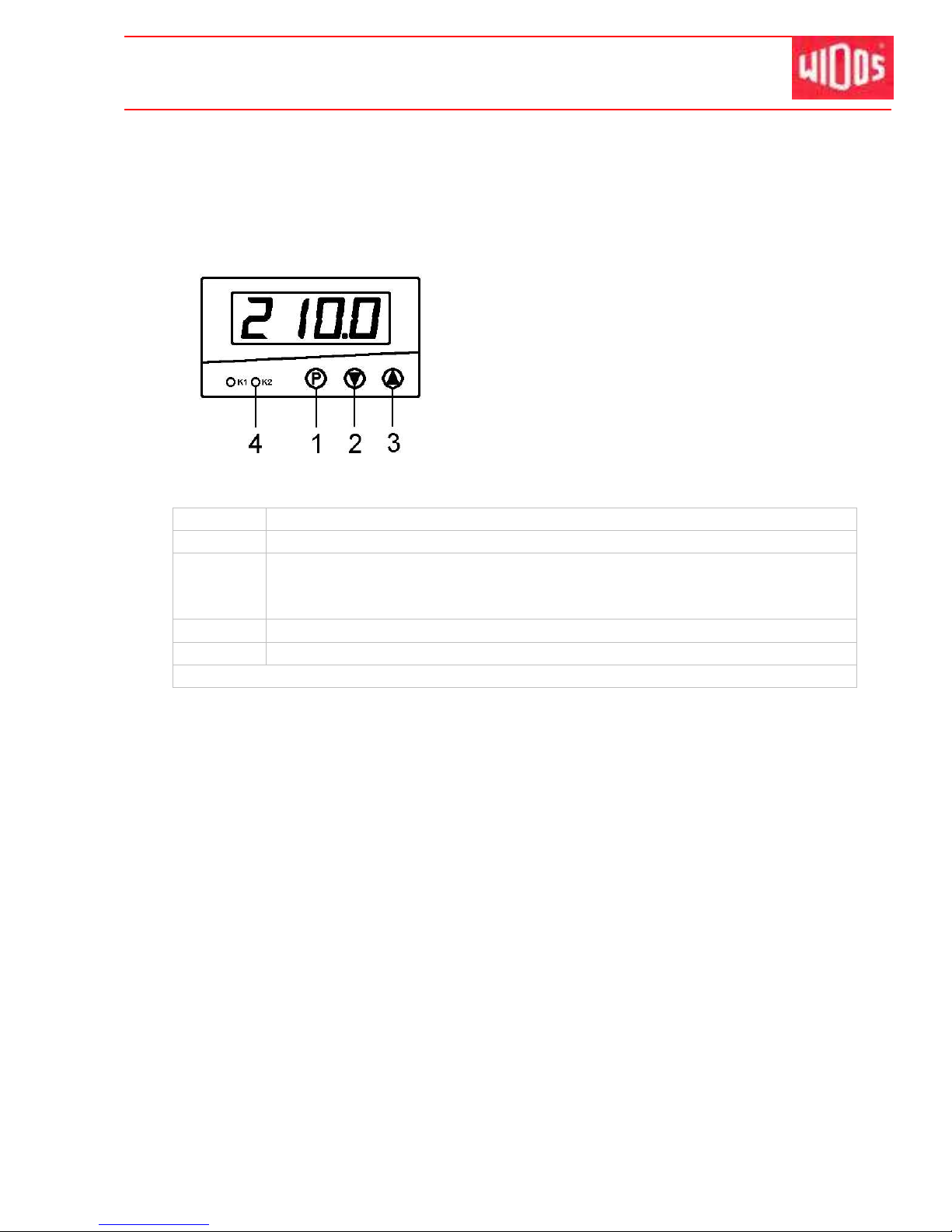
Display = Display of the actual value
Push shortly button P (1), the display shows <SP>,
change desired value with buttons
▲ (3) ▼ (2). Push shortly button P (1), the actual
temperature is displayed again (or automatic change
after 30s). During heating up to desired value, the
control lamp K2 (4) is on. As soon as the desired
temperature is reached, the control lamp K2 (4) is
blinking.
Material Temperature
PE 80
The value for heating element temperature is between (200°C – 220°C *).
PE 100
The standard value for heating element temperature is (220°C).
Increase the change-over time and the welding pressure time at PE 100 as
fast as possible!
PP
The standard value for heating element temperature is (210°C ± 10°C *).
PVDF
The standard value for heating element temperature is (240°C +/- 8°C *).
* The smaller the pipe wall the higher the temperature.
Page 33
Kunststoff schweißtechnik
WIDOS Einsteinstr. 5 Phone ++49 7152 9939 - 0
W. Dommer Söhne GmbH D-71254 Ditzingen-Heimerdingen Fax ++49 7152 9939 - 40
16.01.12 working Instructions WIDOS 20000 page 33 of 98
6. Welding process with SPA 600
Th e re sp ec ti ve ly va li d w el di ng p re sc ri pt io ns ( IS O / CE N / DV S. . . ) a r e t o
b e b as i c al l y f ol lo w ed .
There is a danger of serious injuries: on the one hand between the inner
clamping devices and on the other hand between the outer clamping device
and the end of the guideway.
Do wear safety gloves as a protection against burning.
Noise exceeding 80 dB (A) may occur; during planing it is obligatory to wear ear
protection!
There is danger catchment by planer!
Don’t touch the planer surfaces.
You may run the machine quickly in order to drive the slides back and forth as
well as for the change-over by:
• Pressing <button> (Chapter: 4.2, Nr. 7) and <control lever> on
„FORWARDS“ or „BACKWARDS“.
In order to carry out planing and for the joining you must select the slow speed:
• With <control lever> on „FORWARDS“ or „BACKWARDS“ without pressing
<button>.
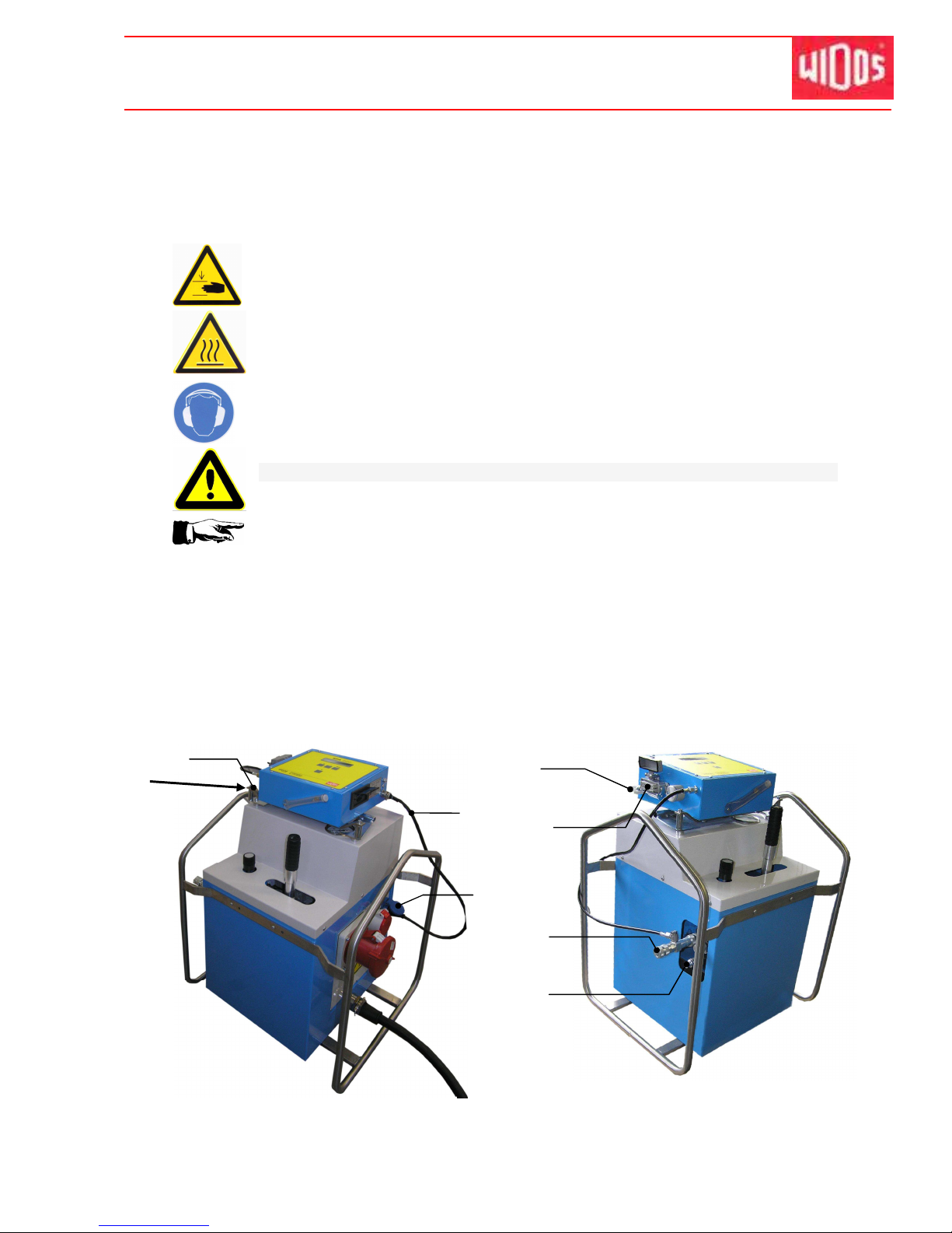
6.1. Connect the SPA 600 to the hydraulic aggregate
5
2
3
4
6
1
7
Page 34
Kunststoff schweißtechnik
Welding process with SPA Chapter 6
16.01.12 Working Instructions WIDOS 20000 Page 34 of 98
• Put the SPA onto the hydraulic aggregate (arrow) and fix it (1).
• In case the T-piece (2) is not mounted to position, remove it from holder (7) and connect it to
the upper hydraulic connector of the aggregate.
• Connect both hydraulic hoses (3) of the basic machine e.g. WIDOS 20000 steel version
there.
• Put the special plug of the heating element into the multipolar power socket at the SPA (5)
and secure by the bracket.
• Connect the plug (4) of the SPA to the power socket (6) at the hydraulic aggregate.
• Connect the mains plug of the hydraulic aggregate to the power supply, observe the correct
voltage (125 A / 400 V / 50 Hz / right hand rotary field).
6.2. Description of the display
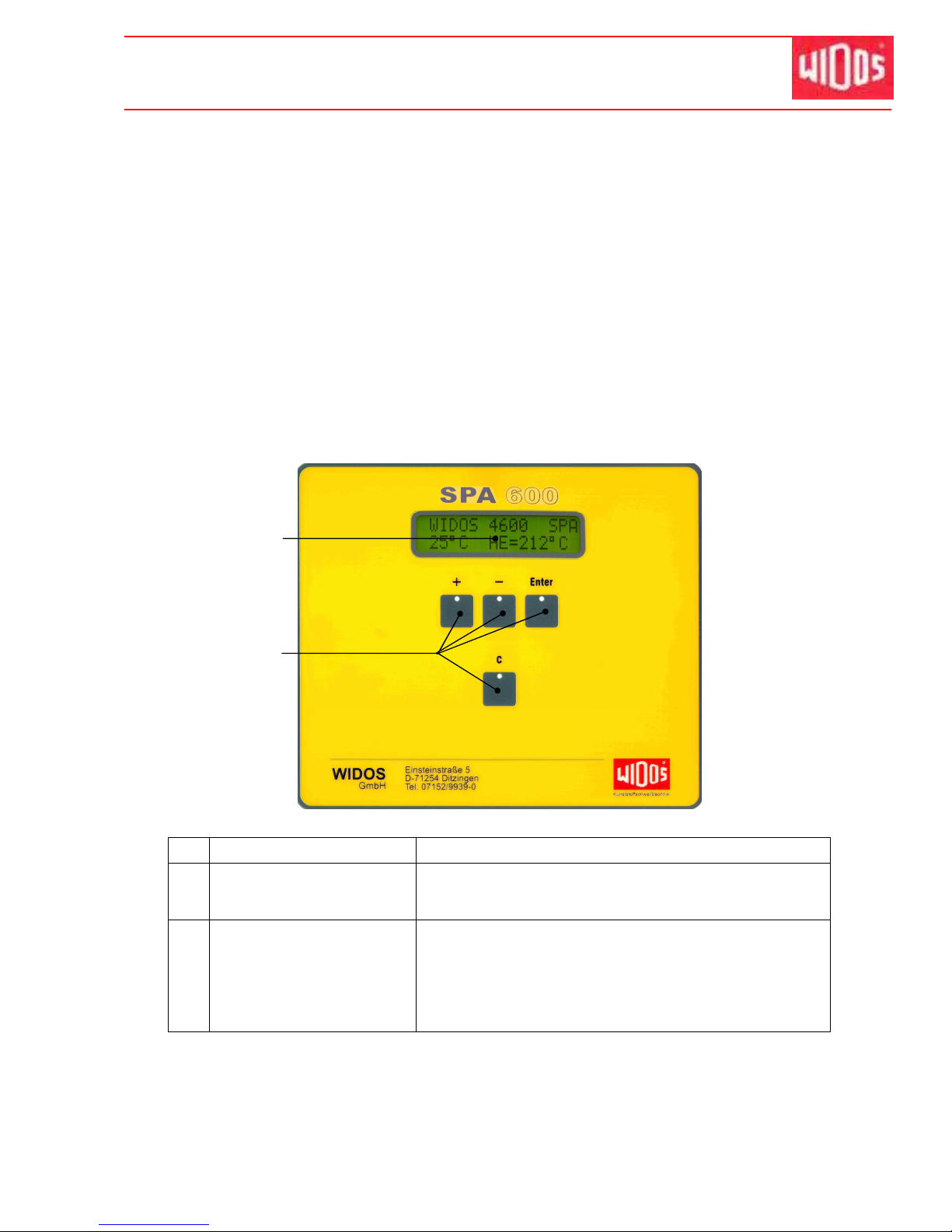
No. Denomination Function
1 Display - Displays the necessary parameters (for welding and
programming).
- Two values can be displayed at the same time.
2 Buttons for operation - Drag pressure measurement;
- Setting the pipe data and the project number;
- Setting the type of the machine;
- Printing the welding data;
- Diagnosis menu;
- Reset to the previous item of the menu.
1
2
Page 35
Kunststoff schweißtechnik
Welding process with SPA Chapter 6
16.01.12 Working Instructions WIDOS 20000 Page 35 of 98
6.3. Programming of the SPA 600
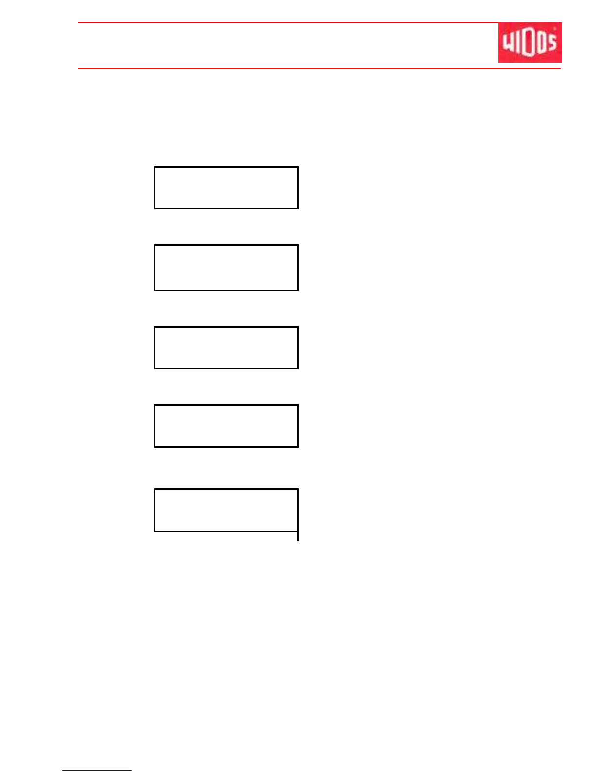
As soon as the main plug is switched on, the display gets bright (the computer is initialized).
after 3 s appears:
Display:
2nd line:
WIDOS GmbH
Germany
after 3 s appears:
Display:
2nd line:
version 0.00.0
sernr 000000
Number of the software version
Serial number of the machine
if the SD card is not formatted, the following message appears:
Display:
2nd line:
convert sd-card for
WICON
Confirm conversion by pressing <+>
Display:
2nd line:
000 free welding
0000 sd-card
Number of free memory capacity (RAM)
Number of free memory capacity sd-Card
after 3 s appears:
„ B a s i c m e n u “
Display:
2nd line:
WIDOS 20000 SPA
11:00 01.12.2011
Display of the currently set machine type
Current time and date
alternating with: 21°C HE= - - - °C current
outside and heating element temperature
In the basic menu, the following possibilities are given:
• The welding process is started by the drag pressure measurement.
• Selecting menu: Select the pipe data and the project number by pressing simultaneously <+>
and <−>.
• Setting menu: Set the machine type and printing the welding data by pressing simultaneously
<−> and <Enter>.
• Diagnosis menu by pressing simultaneously <+> and <Enter>.
Page 36
Kunststoff schweißtechnik
Welding process with SPA Chapter 6
16.01.12 Working Instructions WIDOS 20000 Page 36 of 98
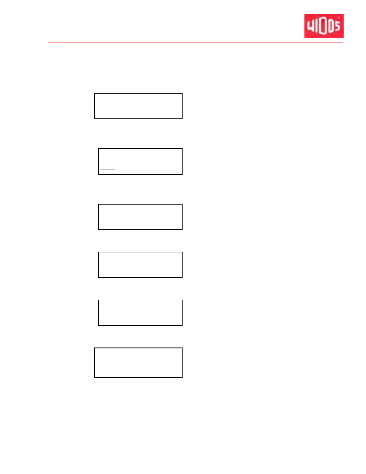
6.3.1. Selection of the pipe data
Abort and back to basic menu by pressing button <C>.
1 step back by pressing button <Enter> (keeping pressed) and pressing button <->.
Display:
2nd line:
WIDOS 20000 SPA
11:00 01.12.2011
Basic menu
By simultaneously pressing buttons <+> and <−>, the pipe data can be
changed by means of the keyboard
Display:
2nd line:
mat diam wall
PE80 20000 53.6
Set the pipe material
Change the material by pressing buttons <+> and <−>,
confirm with button <Enter> and jump to next parameter.
Display:
2nd line:
temp
Next menu by pressing button<Enter>
Display:
2nd line:
name of project
WIDOS
Name of project
Next menu by pressing button<Enter>
Display:
2nd line:
Number of joint
0000
Name of joint
Next menu by pressing button <Enter>
Display:
2nd line:
WIDOS 20000 SPA
11:00 01.12.2011
Display of the currently set machine type
Current time and date
alternating with: 21°C HE= - - - °C current
outside and heating element temperature
Page 37
Kunststoff schweißtechnik
Welding process with SPA Chapter 6
16.01.12 Working Instructions WIDOS 20000 Page 37 of 98
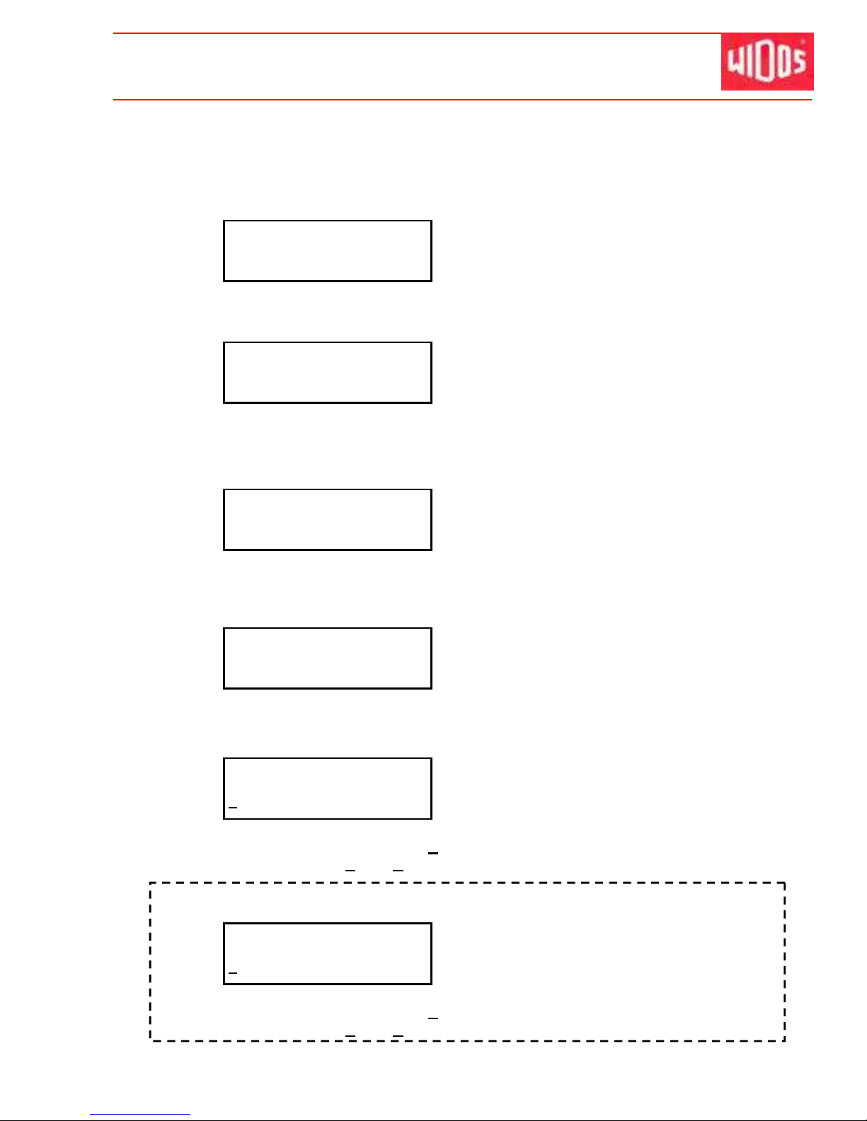
6.3.2. Setting menu
Abort and back to basic menu by pressing button <C>.
One step back by pressing buttons <Enter> (keeping pressed) and <->.
Display:
2nd line:
WIDOS 20000 SPA
11:00 01.12.2011
Basic menu
Next menu by simultaneously pressing buttons <-> and <Enter>
Display:
2nd line:
copy
The SD card is copied by pressing <Enter>.
Next menu by pressing button<Enter>
Display:
2nd line:
Parameter
See chapter: 6.3.2.1
Next menu by pressing <Enter>, by pressing <+> the parameters can be
changed, please see chapter
Display:
2nd line:
Lang. English?
Select languages, English / German
Select the language with buttons <+> and <->
Next menu by pressing button <Enter>
Display:
2nd line:
Traceability
No
Traceability can be select
Press button <+> for Yes
Confirm Yes or No by pressing button <Enter>
In case traceability has been confirmed with „yes“, the display indicates:
Display:
2nd line:
Pipe length
No
Select pipe length for traceability
Press button <+> for Yes
Confirm Yes or No by pressing button <Enter>
Page 38
Kunststoff schweißtechnik
Welding process with SPA Chapter 6
16.01.12 Working Instructions WIDOS 20000 Page 38 of 98
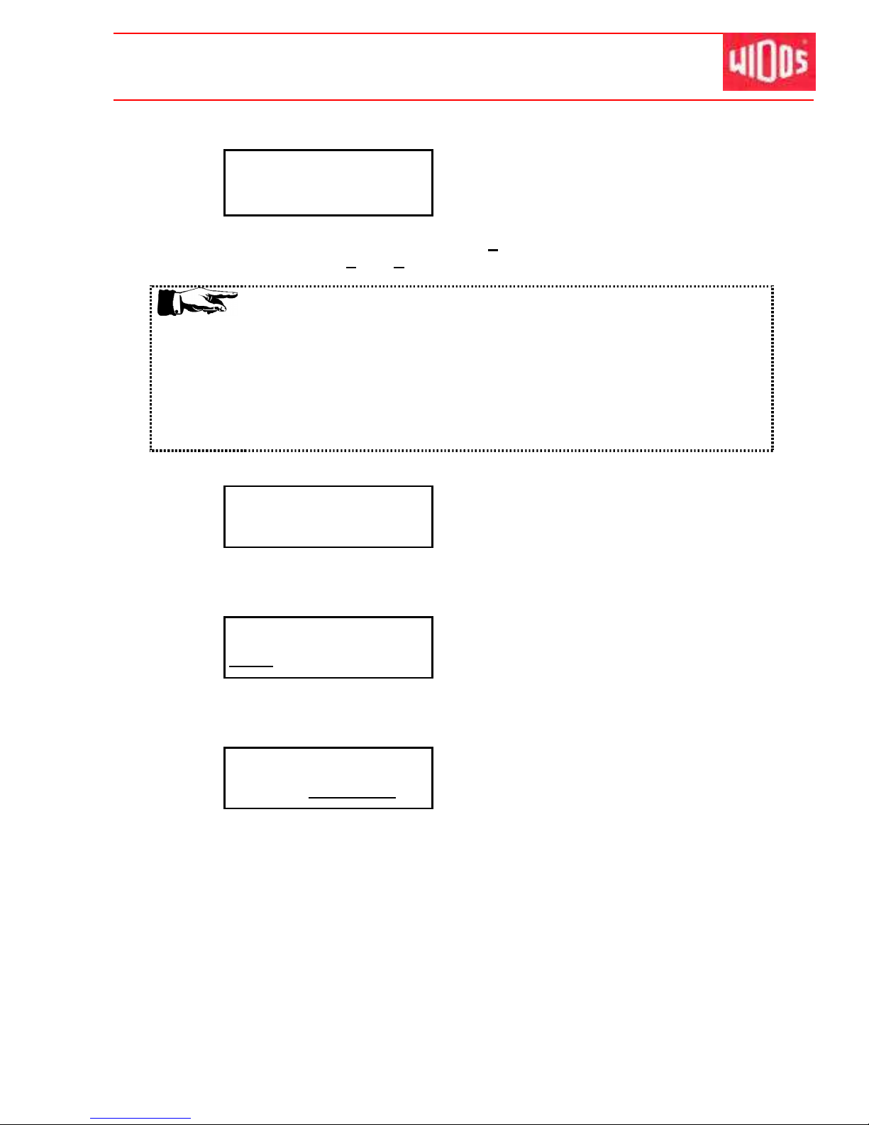
Display:
2nd line:
shortened cooling
no
Select the shortened cooling time
Press button <+> to select for Yes
Confirm Yes or No by pressing button <Enter>
It is allowed to use the shortened cooling time under the following
conditions:
- Welding material: PE and PP
- Prefabrication under workshop conditions
- Low additional pressure at unclamp
- No additional pressure during further cooling down
- Load onto the workpieces only after being completely cooled down
- Work pieces with wall thickness ≥15 mm
Display:
2nd line:
WIDOS 20000 SPA
11:00 01.12.2011
machine type is displayed
Select the machine type with buttons <+>, <-> and <Enter>.
Next menu by pressing button <Enter>
Display:
2nd line:
WIDOS 20000 SPA
11:00 01.12.2011
time is displayed
Set time with buttons <+>, <-> and <Enter>.
Next menu by pressing button <Enter>
Display:
2nd line:
WIDOS 20000 SPA
11:00 01.12.2011
date
Set date with buttons <+>, <-> and <Enter>.
Next menu by pressing button <Enter>
Page 39
Kunststoff schweißtechnik
Welding process with SPA Chapter 6
16.01.12 Working Instructions WIDOS 20000 Page 39 of 98
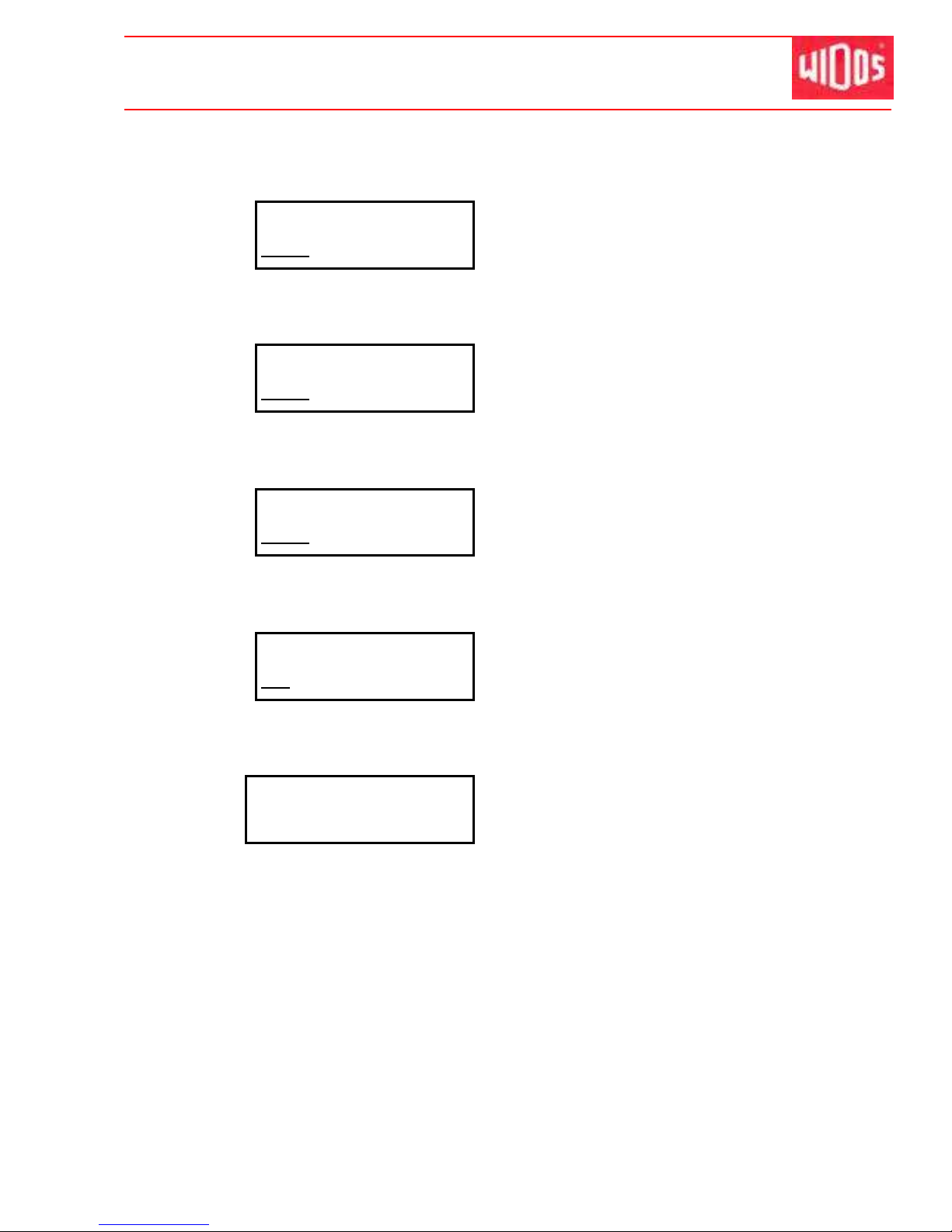
6.3.2.1. Parameter menu / Laboratory menu
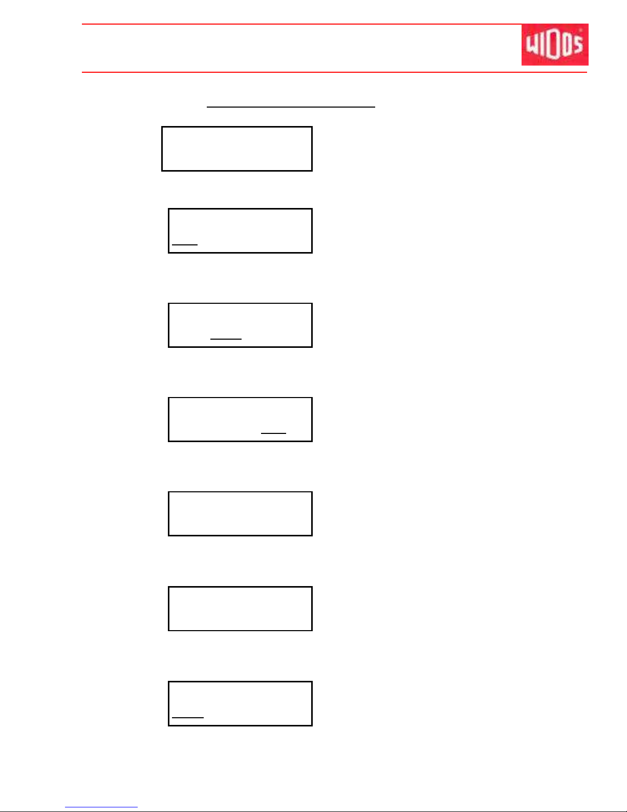
Display:
2nd line:
Parameter
Adjust 40 parameters
By pressing <+> the parameters can be changed via keyboard
Display:
2nd line:
mat diam wall
LAB7 11180 17.2
indication of pipe material, LAB0 – LA39
Change the material by pressing buttons <+> and <->,
confirm with button <Enter> and jump to next parameter.
Display:
2nd line:
mat diam wall
11180 17.2
indication of pipe diameter
Change the pipe diameter by pressing buttons <+> and <->,
Jump to next parameter by <Enter>
Display:
2nd line:
mat diam wall
17.2
indication of pipe thickness
Change the thickness by pressing buttons <+> and <->,
Jump to next parameter by <Enter>
Display:
2nd line:
temperature
214°C
indication of temperature
Change the temperature by pressing buttons <+> and <−>,
By pressing <Enter> the temperature is confirmed.
Display:
2nd line:
align SWP
0.00 N/mm²
indication of aligning pressure
Change the aligning pressure by pressing buttons <+> and <−>,
jump to next parameter by <Enter>
Display:
2nd line:
t-heat
000 s
indication of heating time
Page 40
Kunststoff schweißtechnik
Welding process with SPA Chapter 6
16.01.12 Working Instructions WIDOS 20000 Page 40 of 98
Change the heating time by pressing buttons <+> and <->,
jump to next parameter by <Enter>.
Display:
2nd line:
t-change max.
000 s
indication of change-over time
Change the maximum change over time by pressing buttons <+> and <->,
jump to next parameter by <Enter>
Display:
2nd line:
t-ramp
000 s
indication of ramp time
Change the ramp time by pressing buttons <+> and <−>,
jump to next parameter by <Enter>
Display:
2nd line:
t-cool
000 s
indication of cooling time
Change the cooling time by pressing buttons <+> and <−>,
jump to next parameter by <Enter>
Display:
2nd line:
p-cool
000
Indication of cooling pressure / joining pressure
By pressing <+> and <-> the cooling pressure time is changed,
jump to next parameter by <Enter>
Display:
2nd line:
Parameter
Page 41
Kunststoff schweißtechnik
Welding process with SPA Chapter 6
16.01.12 Working Instructions WIDOS 20000 Page 41 of 98
6.4. Welding process
As soon as the SPA 600 is programmed and connected to the hydraulic aggregate / mains as
described, you can start welding.
Please proceed as follows:
Switch on the heating element and heat it up to welding temperature (chapter: 5.7).
Open and close the basic machine two or three times by means of the valve lever of the
hydraulic aggregate.(„FORWARDS” and „BACKWARDS”)
6.4.1. How to insert the pipes
Lay the pipes into the clamping devices and take care that the upper clamping rings are
mounted with the locking forks showing to the machine center.
Tighten firmly the clamping nuts, respectively close the clamping cylinders and align the pipe
ends with respect to each other.
Always use WIDOS rollerstands for the alignment.
6.4.2. Drag pressure measurement
When the pressure is > 2 bar, the SPA switches from basic menu to drag
pressure measurement.
Slowly press the valve lever until the slide of the basic machine is
closed. The drag pressure must be determined properly since a too high
pressure on small pipe diameters leads to incorrect joining forces.
Release the valve lever.
Drag pressure must be at least 3 bar!
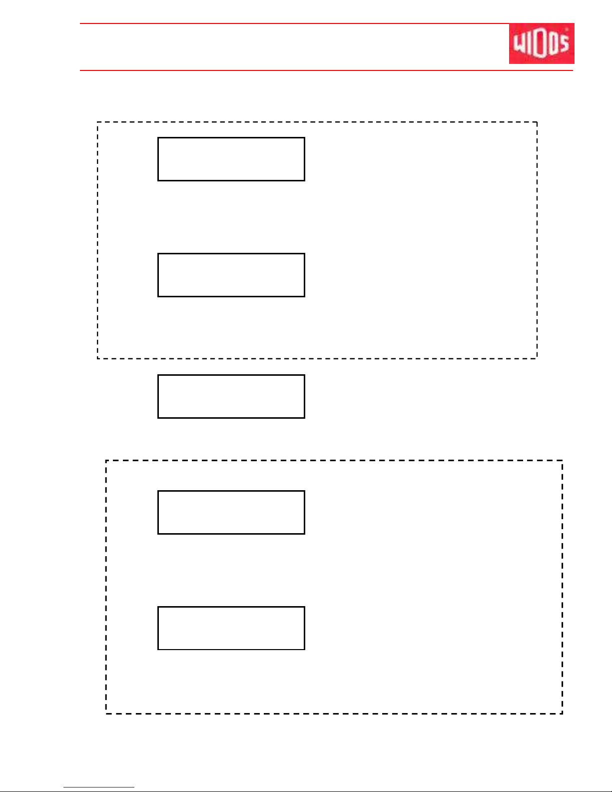
Display:
2nd line:
drag pressure OK?
P0=0 Pi=4
Display of the actual pressure
P0 = desired pressure; Pi = actual pressure
When pressing <Enter>, the actual pressure is taken over as drag
pressure.
Page 42
Kunststoff schweißtechnik
Welding process with SPA Chapter 6
16.01.12 Working Instructions WIDOS 20000 Page 42 of 98
6.4.3. Dimension
In case traceability has been confirmed with „yes“, the display indicates.
Display:
2nd line:
please read in
1st pipe
Either: Read in traceability of the first pipe via the bar code reading pen
Or: Simultaneously pres all buttons <+ / - / Enter>.
Then manually enter barcode of 1st pipe: Select first digit with <+/-> and
jump to the next digit with <Enter>.
Display:
2nd line:
please read in
2nd pipe
Either Read in the traceability of the second pipe via the bar code reading pen
Or: Simultaneously press all buttons <+ / - / Enter>.
Then manually enter barcode of the 1st pipe: Select first digit with <+/->
and jump to the next digit with <Enter>.
Display:
2nd line:
dimension
PE80 1400 34.4
Display of:
Material, pipe diameter and wall thickness
Confirm the dimensions by pressing <Enter>, or interrupt the welding
process by pressing <C> and enter new dimensions.
Only appears in case the pipe length has been selected:
Display:
2nd line:
length pipe 1
+000.00 mm
Enter pipe length of the 1st pipe by <+ / - / Enter>.
Or: Simultaneously pres all buttons <+ / - / Enter>.
Then manually enter barcode of the 1st pipe: Select first digit with <+/-> and jump
to the next digit with <Enter>.
Display:
2nd line:
length pipe 2
+000.00 mm
Either: Enter pipe length of the 1nd pipe by <+ / - / Enter>
Or: Simultaneously pres all buttons <+ / - / Enter>.
Then manually enter barcode of the 1st pipe: Select first digit with <+/-> and jump
to the next digit with <Enter>.
Page 43
Kunststoff schweißtechnik
Welding process with SPA Chapter 6
16.01.12 Working Instructions WIDOS 20000 Page 43 of 98
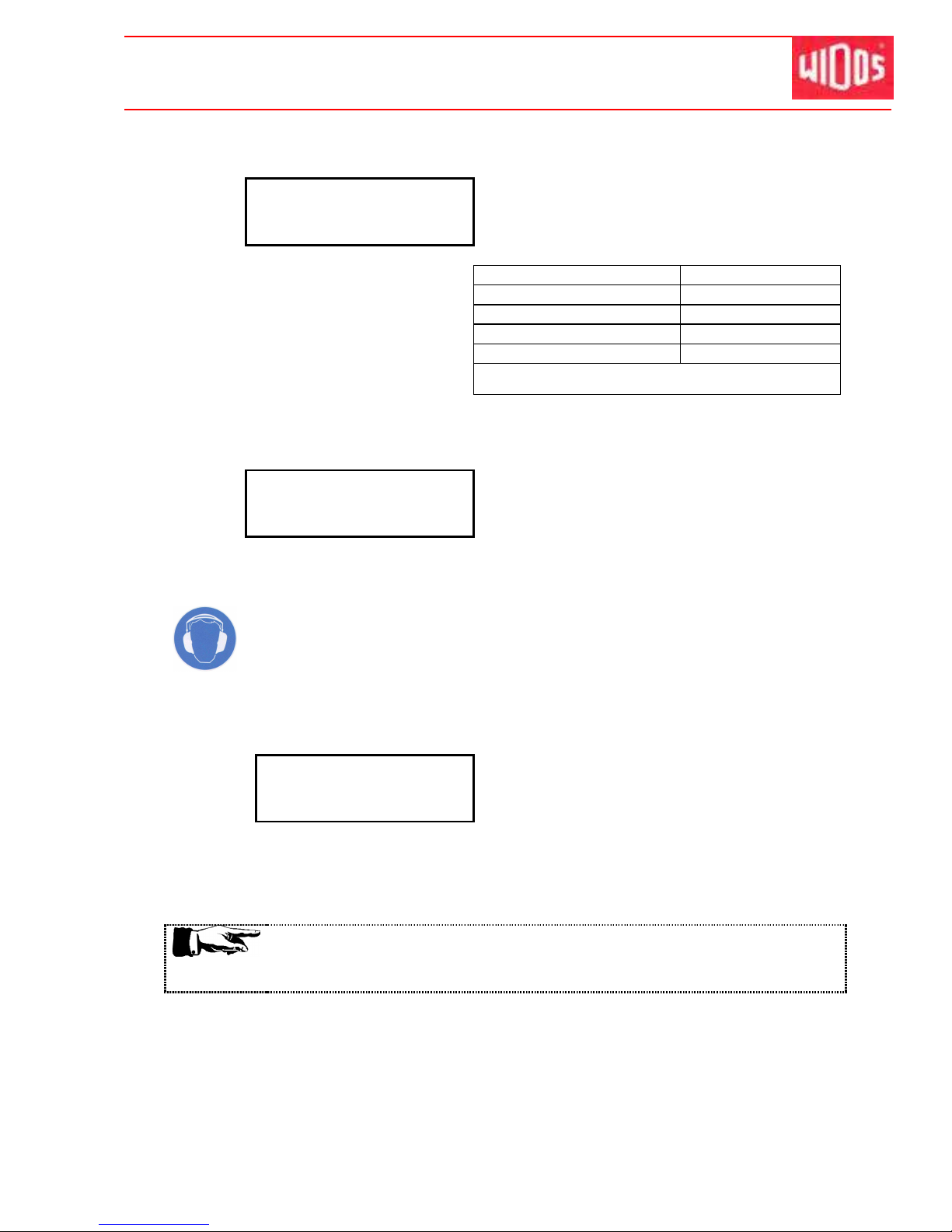
6.4.4. Weather / protection
Display:
2nd line:
weather protect
14 24
Weather character and protective measures
to be taken (according to DVS prescriptions).
Weather character Protective measures
1 = sunny 1 = none
2 = dry 2 = umbrella
3 = rain or snow fall 3 = tent
4 = wind 4 = heater
In case of multiple statement respect the above mentioned
order of the numbers (e.g.: 34 = rain and wind)
Set the weather data by pressing buttons <+> and <->;
confirm the weather data by pressing button <Enter>
Display:
2nd line:
atten! shortened
cooling time
Display of shortened cooling time
6.4.5. Planing
Noise exceeding 80 dB (A) may occur; during planing it is obligatory to wear ear
protection!
Lift planer with the crane and insert it between the pipe ends, lock it and
switch it on; the pressure onto the planer may not exceed 20 bar.
Display:
2nd line:
planer OK?
P0=0 Pi=14
Display of:
Drag pressure and actual pressure
Move the pipe ends onto each other by means of the valve lever and cut
them plane until a circular cutting running 2-3 times around the pipe ends is
formed and the pipe ends are plane.
The planing pressure should be at appr. 10 - 15 bar + drag pressure.
In case there are too many chips stop planer and remove them.
Necessarily take care that no chips will be drawn-in between the planer
discs.
You must carry out planing as long as a revolving chip (three times) has
formed.
Separate the pipes, with <control lever> on „BACKWARDS“ until the chip
will tear off, only then switch off planer.
Detach the planer locking device and lift crane out of the machine again.
Remove the produced chips without contacting the worked surfaces.
Page 44
Kunststoff schweißtechnik
Welding process with SPA Chapter 6
16.01.12 Working Instructions WIDOS 20000 Page 44 of 98
When planning is o.k. confirm it by pressing <Enter>.
Abort and back to basic menu by pressing <C>.
One menu step back by pressing <Enter> (keep pressed) and <->.
6.4.6. Compensation of mismatch
Move pipe ends onto each other, press the control lever on „FORWARDS“.
Display:
2nd line:
alignment
T=210°C Pi=12
Display of:
Heating element temperature and actual pressure
After releasing the pressure, the following message appears:
Display:
2nd line:
alignment OK
?
T=210°C Pi=12
Display of:
Heating element temperature and actual pressure
If the alignment of the pipes is correct, open the machine and confirm with
button <Enter>.
The mismatch may not exceed 10 % of the wall thickness, the allowed gap
may be max. 2.0 mm.
In case of higher mismatch, readjust the pipe ends in the clamping devices
and repeat the planing process.
Open pipe ends with <control lever> on „BACKWARDS“
Abort the welding process by pressing button <C>.
6.4.7. Bead up
Lift heating element with the crane and insert it between the pipe ends.
Drive the pipes continuously to the heating element, < control lever > on
“FORWARDS”.
Take care that the heating element lies in the zone of the
diminution of the tear
-
off bar
.
Page 45
Kunststoff schweißtechnik
Welding process with SPA Chapter 6
16.01.12 Working Instructions WIDOS 20000 Page 45 of 98
Display:
2nd line:
bead up
Ps=15 Pi=3
Display of:
desired and actual pressure
alternating with
Display:
2nd line:
bead up
T=210°C Pi=3
Display of:
Heating element temperature and actual pressure
Slowly increase pressure until actual pressure = desired pressure (when
desired pressure is reached, a beep sound can be heard).
Maintain pressure until the pipe end lays completely at the heating element
and a bead according to DVS has been formed.
6.4.8. Heating up
Reduce pressure with < control lever> on: „Pressure release“ until the
heating pressure is = 0 the SPA control switches to heating.
Important ! Do not open the basic machine.
Display:
2nd line:
heat up
t=534s Pi=0
Display of:
Remaining time for heating and actual pressure
alternating with
Display:
2nd line:
heat up
T=210°C Pi=0
Display of:
Heating element temperature and actual pressure
At the end of the heating time, the button <Enter> flashes and a beep
sound can be heard.
6.4.9. Change over
Press button <Enter>.
Open slides quickly therefore press the button and move <control lever> on
“BACKWARDS” until the heating element detaches from both pipe ends.
Remove heating element out of the machine quickly and move pipe ends
together <control lever> on “FORWARDS”.
Display:
2nd line:
chg. over
t=21s Pi=0
Remaining change over time and actual pressure
Page 46
Kunststoff schweißtechnik
Welding process with SPA Chapter 6
16.01.12 Working Instructions WIDOS 20000 Page 46 of 98
6.4.10. Pressure ramp
Continuously increase the pressure up to desired pressure within the
prescribed time for the pressure ramp with <control lever> on
“FORWARDS”.
Display:
2nd line:
ramp
t=27s Pi=6
Display of:
Heating element temperature and actual pressure
6.4.11. Joining and cooling
Display:
2nd line:
cooling
t=3:32 Pi=12
Remaining cooling time (minutes) and actual
pressure
alternating with
Display:
2nd line:
cooling
Ps=12 Pi=12
Comparison desired and actual pressure
In case of decrease of pressure during cooling time, a beep sound can be
heard. Readjust pressure onto desired pressure.
6.4.12. Completion of welding
Display:
2nd line:
SD card 0000
Welding parameters will be saved on the SD card
(if present).
0000 = Number of weldings saved on the SD card.
Welding parameters are stored to the SD card (if available).
Display:
2nd line:
tabl. of errors
parameter OK
Display in case of a fault-free welding.
Or: welding is finished with shortened cooling time:
Display:
2nd line:
shorten cooling t
parameter OK
Or:
Display:
2nd line:
tabl. of errors
TAWURtp9
Display of the errors occurred during welding
(see chapter: 6.4.13).
Page 47
Kunststoff schweißtechnik
Welding process with SPA Chapter 6
16.01.12 Working Instructions WIDOS 20000 Page 47 of 98
Release pressure, with <control lever> on „Pressure release“
Do not open the basic machine!
Release clamping nuts and remove upper clamping rings.
Remove welded part.
Open machine with <control lever> auf „BACKWARDS“.
Confirm the end of the welding with <Enter>.
6.4.13. Signification of the error codes
• T Heating element temperature
• A Bead up
• W Heating
• U Change over
• R Pressure ramp
• t Cooling time
• p Cooling pressure
• 9 Environmental temperature <0°C
6.4.14. Copying the internal data on SD - card and deleting internal data
(RAM)
Abort and back to basic menu by pressing button <C>.
One step back by pressing buttons <Enter> (keeping pressed) and <->.
Display:
2nd line:
WIDOS 20000 SPA
11:00 01.12.2011
Basic menu
Next step by pressing simultaneously buttons <−> and <Enter>.
Display:
2nd line:
copy
_
By pressing <+> you can copy the data from the internal memory onto the
SD card.
Only displayed if there is no card in the drive:
Display:
2nd line:
error SD card
Message appears if there is no SD card in the
drive
Confirm the error message by pressing <Enter>.
When an error occurs, these error codes
are also displayed in the first line of the
display during the welding process.
Page 48
Kunststoff schweißtechnik
Welding process with SPA Chapter 6
16.01.12 Working Instructions WIDOS 20000 Page 48 of 98
Display:
2nd line:
delete SPA-RAM?
Delete internal memory (RAM) by pressing button <+>.
When pressing button <->, the internal memory (RAM) will not be
deleted.
Display:
2nd line:
copy
_
Either: press several times button <Enter>.
Or: after a short while appears automatically:
Display:
2nd line:
WIDOS 20000 SPA
11:00 01.12.2011
Display of the currently set machine type
Current time and date
alternating with: 21°C HE= - - - °C current
outside and heating element temperature
„ b a s i c m en u “
6.5. SD card and drive
The SPA 600 can be equipped optionally with a drive for a SD card.
The apparatus then stores the welding data in the internal memory as well as on the SD card if
a card is in the drive.
On a card with 64 MB memory capacity, the welding data of about 32000 weldings can have
place.
• The SD card must be formatted with „FAT16“ before usage.
• Insert the card with the arrow to the top and in direction of the arrow (socket side) carefully
and with a low pressure into the reading unit.
• The card can be read out with a WICON program (optional).
• The card may not be bent, opened, overheated and become wet!
Please only use SD cards purchased from WIDOS. We will not be liable for
any cards from other manufacturers!
6.6. Bar code reading pen (optional)
In order to read the bar code, glide smoothly over the bar code with the bar code reading pen
(maintained vertically).
The reading pen is ready as soon as the red light at its end is on.
Page 49
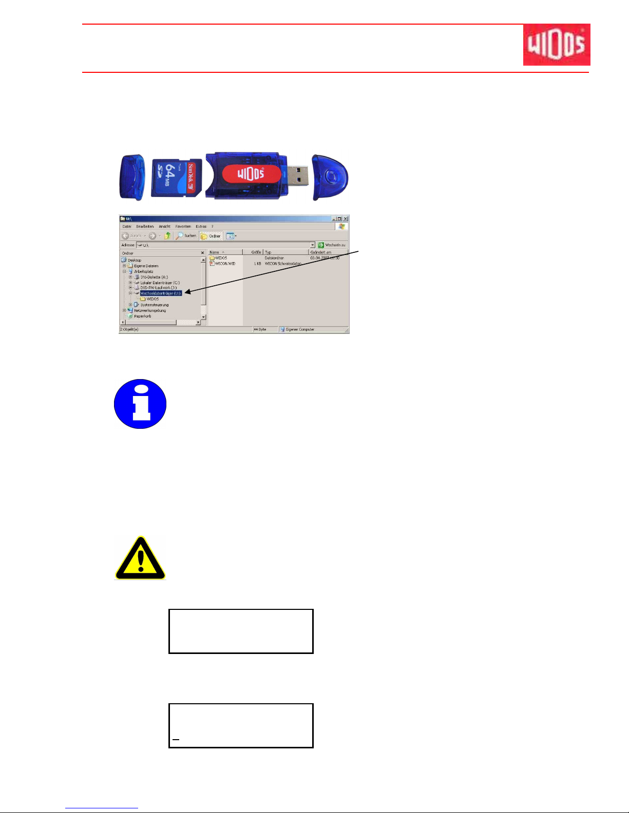
Kunststoff schweißtechnik
Welding process with SPA Chapter 6
16.01.12 Working Instructions WIDOS 20000 Page 49 of 98
6.7. How to read out WICON with USB card reader (optional)
You may read out the welding data onto a PC by the USB card reader.
Remove the card from the SD card drive of the SPA-600.
Remove the rear cap and plug card
according to the image into the USB card
reader.
Remove the front cap and plug USB card
reader into the USB interface in your PC.
As soon as the USB card reader has been
plugged, it appears as removable medium
in the drive list.
Open the WIDOS folder, there you will find:
- WICON2000 viewer for considering and
printing the welding data,
- working instructions for WICON2000
viewer as PDF file.
6.8. How to read the welding data
The battery-buffered memory (RAM) can store about 400 weldings.
Make sure not to go over this quantity (in the display the error message
"memory full“ appears) because otherwise the first stored welding (001) will be
overwritten (if necessary, read the welding data on the SD card out in time).
6.9. Diagnosis program
The purpose of the diagnosis program is the control and the modification of stored machine
parameters.
In the following lines, all important diagnosis numbers for the function tests are described.
Inappropriate operation of the diagnosis functions may lead to disturbances in
the machine and may destroy components.
The diagnosis functions allow a direct access to the specific parameters of the
machine and have to be operated only by skilled staff.
Display:
2nd line:
WIDOS 20000 SPA
11:00 01.12.2011
Basic menu
Press simultaneously buttons <+> and <Enter> to enter the diagnosis
program from the basic menu.
Display:
2nd line:
WIDOS 20000 SPA
0000
Enter the diagnosis number
Page 50
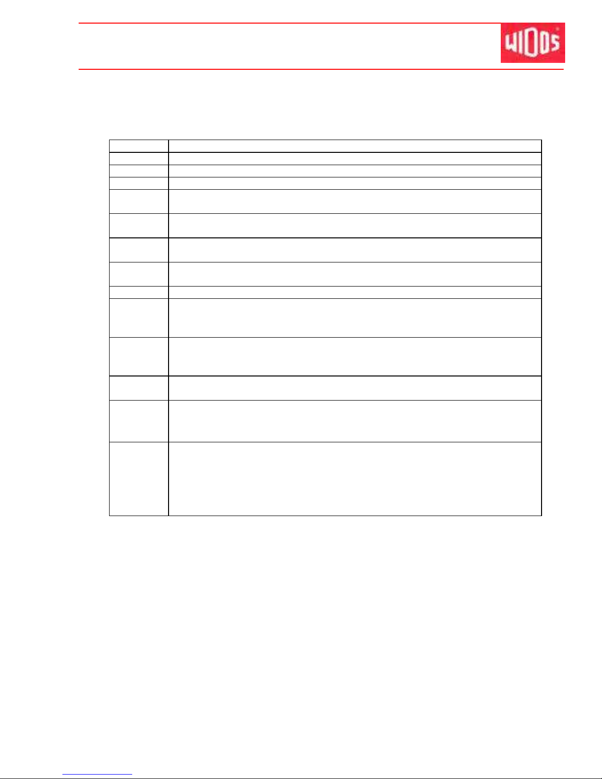
Kunststoff schweißtechnik
Welding process with SPA Chapter 6
16.01.12 Working Instructions WIDOS 20000 Page 50 of 98
Enter the required diagnosis number by pressing buttons <+>, <−> and
<Enter>.
One step back by pressing buttons <Enter> (keeping pressed) and <->.
No. Signification
0010 - The actual temperature (°C) of the heating element is displayed
0011 - The environmental temperature (°C) is displayed
0012 - The pressure or the force (bar or N) is displayed
0014 - The required heating time which was calculated by the programmed welding
parameters is displayed
0015 - The required change over time which was calculated by the programmed
welding parameters is displayed
0016 - The required time for pressure ramp which was calculated by the
programmed welding parameters is displayed
0017 - The required cooling time which was calculated by the programmed welding
parameters is displayed
0018 - The required cooling pressure is displayed
0022 - Selection of SDR / wall thickness in the display
0000 mm
0002 SDR
0023 - The automatic change to summer or winter time may be switched on or off
0000: change summer / winter time switched off
0001: change summer / winter time switched on
0027 - All internal values, such as printing offset, temperature straight line ramp, etc.
are displayed on the laptop
0030 - All stored weldings are deleted
When entering 0001, all weldings stored in the RAM memory up to that time
are deleted
0034 - Bit values from 0-1023 appear which will change together with the change of
the corresponding analog values
8 Environmental temperature
9 Heating element temperature NTC
10 Pressure (4-20 mA)
11 Heating element temperature PT 1000
Page 51
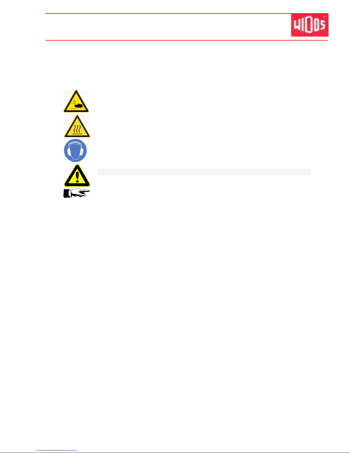
Kunststoff schweißtechnik
WIDOS Einsteinstr. 5 Phone ++49 7152 9939 - 0
W. Dommer Söhne GmbH D-71254 Ditzingen-Heimerdingen Fax ++49 7152 9939 - 40
16.01.12 working Instructions WIDOS 20000 page 51 of 98
7. Welding process without SPA
Th e re sp ec ti ve ly va li d w el di ng p re sc ri pt io ns ( IS O / CE N / DV S. .. ) a r e
t o b e ba si ca ll y fo ll ow e d.
There is a danger of serious injuries: on the one hand between the inner
clamping devices and on the other hand between the outer clamping device and
the end of the guideway.
Do wear safety gloves as a protection against combustion.
Noise exceeding 80 dB (A) may occur; during planing it is obligatory to wear ear
protection!
There is danger of catching by the planer!
Do not touch the planer surfaces.
You may run the machine quickly in order to drive the slides back and forth as
well as for the change-over by:
• Pressing <button> (Chapter: 4.2, Nr. 7) and <control lever> on
„FORWARDS“ or „BACKWARDS“.
In order to carry out planing and for the joining you must select the slow speed:
• With <control lever> on „FORWARDS“ or „BACKWARDS“ without pressing
<button>.
• A stop-watch must be available to record the actual times for heating and cooling.
• A welding table must be available from which the parameters for the pipe dimensions to be
welded prescribed by the welding prescriptions may be taken.
• The heating element surfaces must be clean, especially non greasy, therefore they need to
be cleaned shortly before each welding or in case of dirtiness by means of a fiber-free
paper and a cleaning agent (e.g. PE cleaner). The anti-adhesive coating of the heating
element must remain undamaged in the working area.
• Switch on the heating element and set the required welding temperature (standard value for
PE-HD: 210°C) at the temperature regulator (chapter: 5.7).
- If the control lamp <K2> blinks, the desired temperature is reached and maintained by a
certain pulse-position ratio.
• Put the pipes into the lower parts of the clamping ring. In order to carry out planing you
must place the pipes in a way that they overlap by 110 – 120 mm to the inside.
• Put on the upper parts of the clamping ring and tighten the pipes with the clamping nuts
and adjust the workpieces to each other. Use WIDOS roller stands for that purpose.
• Close the slides <valve lever> on „FORWARDS“ thereby reading the movement pressure
on the pressure gauge.
The movement pressure is displayed exactly when the slide with the clamped pipe passes
over into its movement.
Page 52
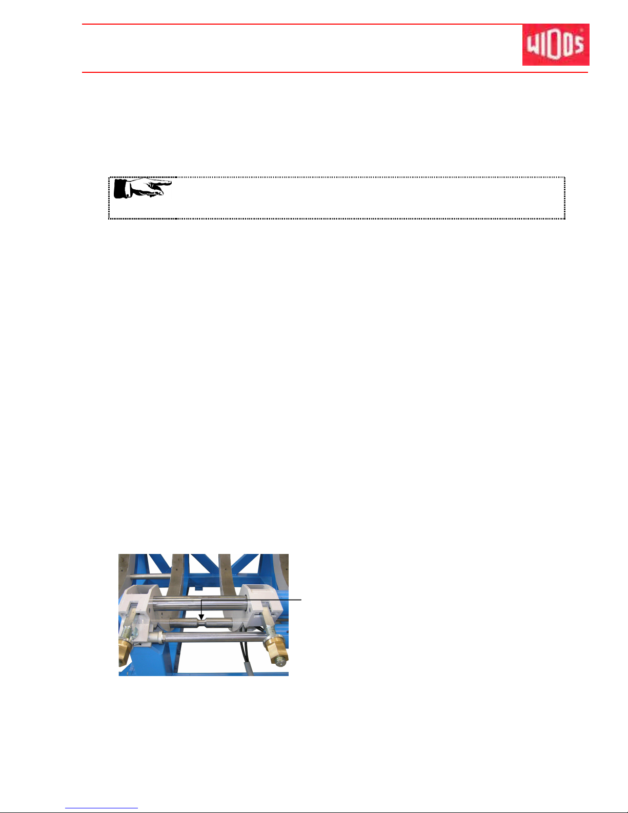
Kunststoff schweißtechnik
Welding process without SPA Chapter 7
16.01.12 Working Instructions WIDOS 20000 Page 52 of 98
• Open slides <valve lever> on „BACKWARDS“.
• Lift planer with the crane between the clamping tools and fix with the planer locking device
(chapter: 4.6, no. 43) into the basic machine.
• Switch on the planer, move pipes together with <valve lever> on „FORWARDS“ and start
planing the pipes. You should carry out planing at a pressure of max. 10 - 15 bar.
In case there are too many chips, stop the planer and remove them.
Necessarily take care that no chips will be drawn-in between the planer
discs.
• You must carry out planing as long as a revolving chip (three times) has formed.
• Separate the pipes, with <valve lever> on „BACKWARDS“ until the chip will tear off, only
then switch off planer.
• Detach the planer locking device by pulling the ball head away from the machine and lift
crane out of the machine again.
• Remove the produced chips without contacting the worked surfaces.
• Shut slides, <valve lever> on „FORWARDS“.
• Check pipe mismatch and gap on the joining pipe ends. According to DVS 2207, the
mismatch on the pipe outer side must not exceed 0.1 x pipe wall thickness, the admissible
gap must not exceed 2,0 mm. The mismatch compensation is carried out by further
tightening or releasing of the clamping nuts. In case mismatch compensation was carried
out, planing must be repeated afterwards.
• The adjustment pressure for the pipe dimension to be welded can be gathered from the
welding table. Add the movement pressure.
• Set the resulting pressure value at the pressure relief valve and check it by actuating the
<valve lever>.
• Open slides again slightly, <valve lever> on „BACKWARDS“.
• Gather heating time, maximum change over time, cooling time and bead height for the pipe
dimension to be welded from the table.
• Move the heating element which has been cleaned and brought to desired temperature
between the pipes with the crane.
• Shut slides smoothly to the set adjustment pressure, <valve lever> on „FORWARDS“.
Take care that the heating element lies in the
zone of the diminution of the tear-off bar.
Page 53
Kunststoff schweißtechnik
Welding process without SPA Chapter 7
16.01.12 Working Instructions WIDOS 20000 Page 53 of 98
• When the prescribed revolving bead height is reached, reduce pressure. For this purpose,
move the <valve lever> „Pressure release“ until the desired heating pressure is built up
(heating pressure = approx. 10% of the adjustment pressure).
• The heating up time starts now. Press the stop-watch and compare the actual time with the
nominal time taken from the table.
• After expiration of the heating time, open the slide quickly with button on valve lever and
<valve lever> on „BACKWARDS“, remove the heating element as quickly as possible. Then
close the slide smoothly, <valve lever> on „FORWARDS“.
The maximum time frame for this process is predetermined by the value for the change
over time taken from the table.
• When the welding pressure is built up, press the stop-watch and keep the <valve lever> for
approximately 10s on position „FORWARDS“ so that the hydraulic accumulator can be
filled. During the cooling time re-adjust pressure, if necessary (the pressure for cooling is
the same as the set adjustment pressure).
• After expiration of the cooling time release pressure with <valve lever> on „Pressure
release“.
Important! Do not open the basic machine!
• Release the clamping nuts and remove the upper clamping ring.
• Remove the welded part and open the slide with <valve lever> on „BACKWARDS“.
The wel d in g pr oc es s is fin i shed .
Page 54

Kunststoff schweißtechnik
WIDOS Einsteinstr. 5 Phone ++49 7152 9939 - 0
W. Dommer Söhne GmbH D-71254 Ditzingen-Heimerdingen Fax ++49 7152 9939 - 40
16.01.12 Working Instructions WIDOS 20000 Page 54 of 98
8. Welding log and tables
Page 55
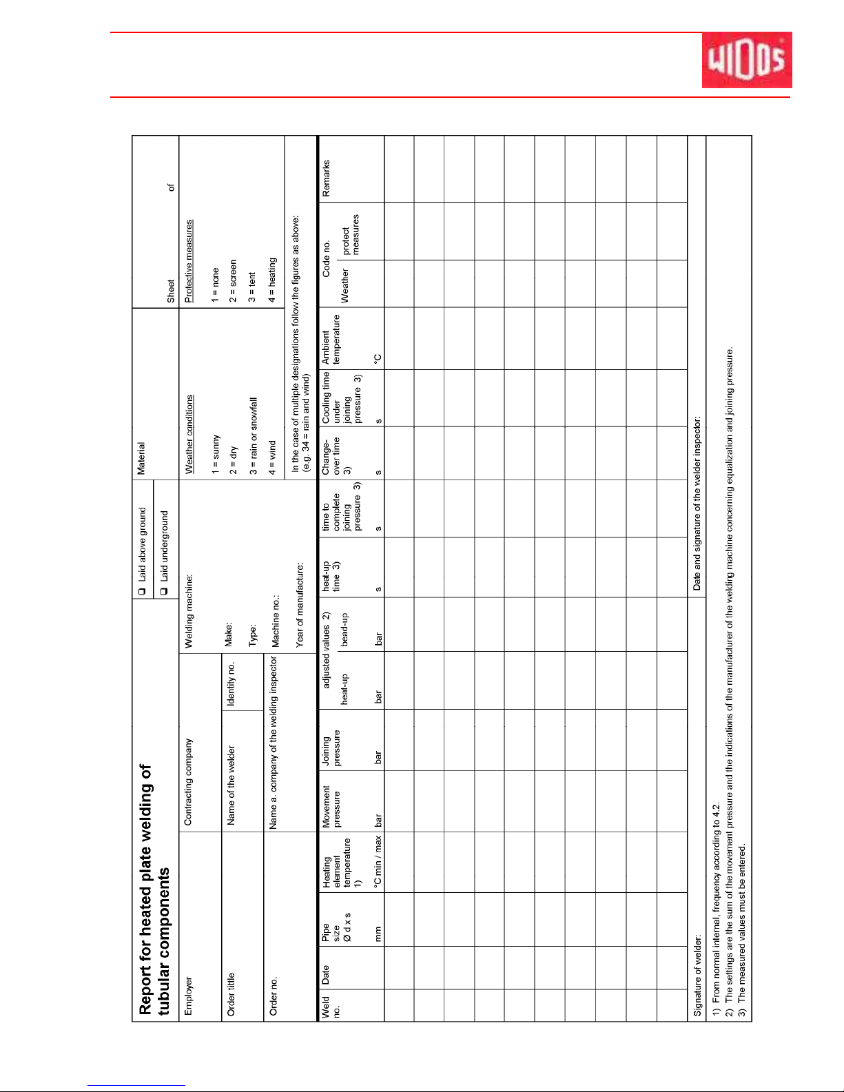
Kunststoff schweißtechnik
Welding log and tables Chapter 8
16.01.12 Working Instructions WIDOS 20000 Page 55 of 98
Page 56
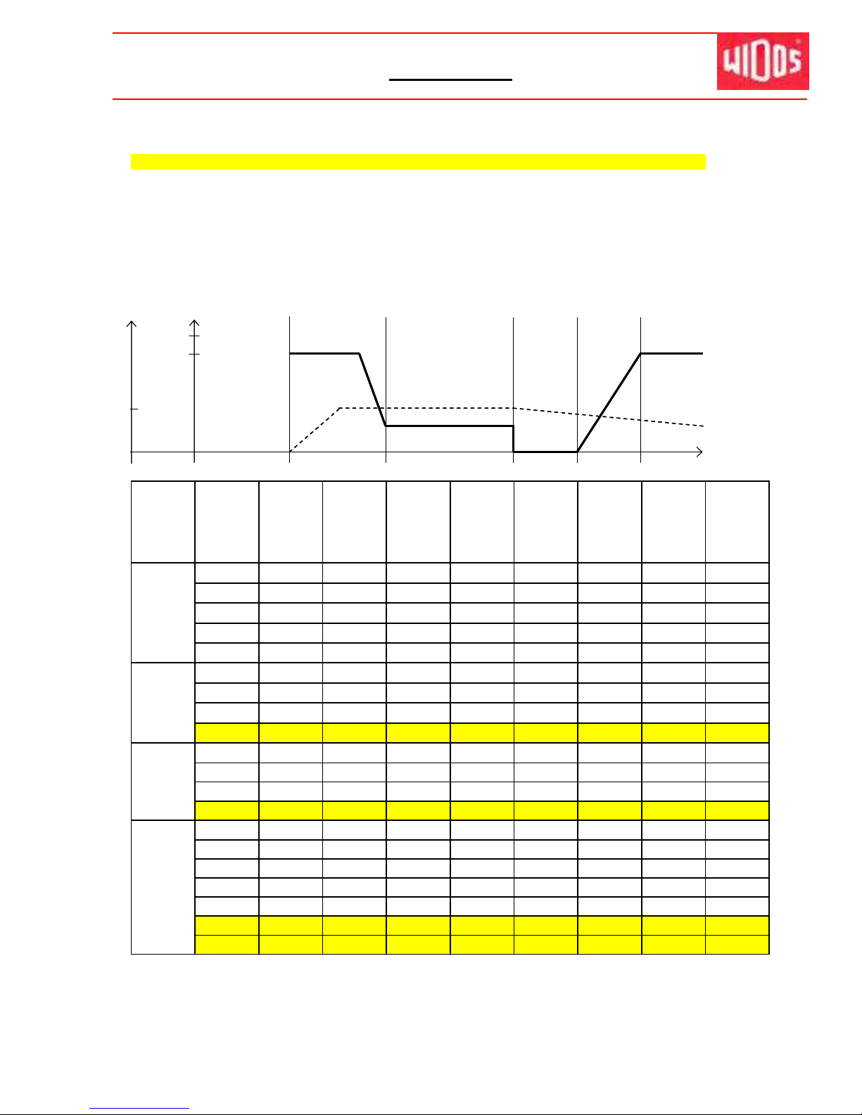
Kunststoff schweißtechnik
Foundation: 2207, 2208 DIN 16932 German association for welding
Use for:
WIDOS
20000
DA 1200 mm - 2000 mm
The data in the colored, labeled arrays are interpolated, no garantee, based on DVS 2207 part 1
1 bar on manometer:
613
N
PE 80
The value for heating element temperature is between 200° C - 220° C.
The
smaller
the pipe wall the
higher
the temperature.
PE 100
The standard value for heating element temperature is 220° C.
Increase the change-over time and the welding pressure time at PE 100 as fast as possible !
time to
change- reach full
over welding cool-down time
0,15 (PE) time pressure
pressure in
T
desired
temperature
time
pipe
pipe
SDR
bead-up
circular
heat-up
max.
time welding
cool-
diameter
wall
pressure
bead
time
change-
to reach
pressure
down
OD
(s)
[bar]
min.
[s]
over
welding
[bar]
time
[mm]
[mm]
time
pressure
[min]
[s] [s]
1200
29,4 41 27 3,0 294 13 16 27 36
1200
36,7 33 33 3,0 367 16 19 33 45
1200
45,9 26 41 3,5 459 19 23 41 55
1200
57,2 21 51 4,0 572 22 29 51 67
1200
68,0 17,6 60 4,0 680 24 34 60 78
1400
34,4 41 37 3,0 344 15 18 37 42
1400
42,9 33 45 3,5 429 18 22 45 52
1400
53,5 26 56 4,0 535 21 27 56 64
1400
82,4 84 4,5 840 21 27 84 56
1600
39,2 41 48 3,5 392 17 20 48 48
1600
49,0
33593,5
49020255959
1600
61,2
26734,0
61223317371
1600 94,1 109 5,0 941 30 48 109 103
1800
48,3
66 3,5 483 19 24 66 58
1800 49,0 66 3,5 490 20 25 66 59
1800 60,9 82 4 609 23 30 82 71
1800 61,4 83 4 614 23 31 83 71
1800 69,1 92 4 691 25 35 92 79
1800 71,6 96 4,5 716 25 36 96 81
1800 105,9 138 5,0 1059 32 54 138 114
bead-up heat-up
welding area
in welding area
Table for PE
Additional to the given bead-up force and to the welding force the moving force of the support must be added !
P (N/mm²)
16.01.2012 Working instructions WIDOS 20 000 Page 56 / 1 of 98
Page 57
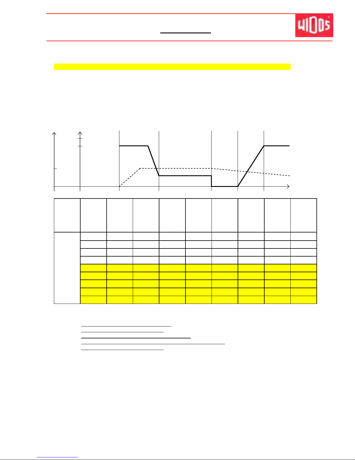
Kunststoff schweißtechnik
Foundation: 2207, 2208 DIN 16932 German association for welding
Use for:
WIDOS
20000
DA 1200 mm - 2000 mm
The data in the colored, labeled arrays are interpolated, no garantee, based on DVS 2207 part 1
1 bar on manometer:
613
N
PE 80
The value for heating element temperature is between 200° C - 220° C.
The
smaller
the pipe wall the
higher
the temperature.
PE 100
The standard value for heating element temperature is 220° C.
Increase the change-over time and the welding pressure time at PE 100 as fast as possible !
time to
change- reach full
over welding cool-down time
0,15 (PE) time pressure
pressure in
T
desired
temperature
time
pipe
pipe
SDR
bead-up
circular
heat-up
max.
time welding
cool-
diameter
wall
pressure
bead
time
change-
to reach
pressure
down
OD
(s)
[bar]
min.
[s]
over
welding
[bar]
time
[mm]
[mm]
time
pressure
[min]
[s] [s]
bead-up heat-up
welding area
in welding area
Table for PE
Additional to the given bead-up force and to the welding force the moving force of the support must be added !
P (N/mm²)
2000
53,6
81 4,0 536 21 27 81 64
2000
54,5 82 4,0 545 21 27 82 65
2000
67,7 101 4,5 677 24 34 101 78
2000
68,2 102 4,5 682 25 34 102 78
2000 76,9 114 4,5 769 26 39 114 87
2000 79,5 118 5,0 795 27 40 118 89
2000 76,9
114 4,5 769 26 39 114 87
2000
79,5 118 5,0 795 27 40 118 89
2000 117,6 171 5,0 1176 35 61 171 125
Remaining under the cool-down time for up to 50% is allowed under the following conditions:
•
prefabrication under workshop conditions
•
low additional pressure at unclamping
•
no additional pressure during further cooling down
•
load onto the workpieces only after being completely cooled down
•
Join parts with wall thickness
≥15 mm
16.01.2012 Working instructions WIDOS 20 000 Page 56 / 2 of 98
Page 58
Kunststoff schweißtechnik
WIDOS Einsteinstr. 5 Phone ++49 7152 9939 - 0
W. Dommer Söhne GmbH D-71254 Ditzingen-Heimerdingen Fax ++49 7152 9939 - 40
16.01.12 Working Instructions WIDOS 20000 Page 57 of 98
9. Maintenance, care and repair
Goal of the chapter is:
• Keeping the nominal state and the operation capacity of the machine.
• Increasing the efficiency by avoiding non-planned outage.
• Efficient planning of the maintenance work and the maintenance tools.
9.1. Maintenance and inspection, repair
All maintenance and repair work have to be basically performed with the
machine in off position.
During this the machine has to be secured against unauthorized switching on.
Prescribed maintenance and inspection work should be performed in time.
The DVS gives the advice of inspection work after 1 year.
For machines with a specially high usage percentage the testing cycle should be
shortened.
The work should be performed at the WIDOS GmbH company or by an
authorized partner.
• The operators are to be informed prior to the maintenance and repair work.
• In general, take care for tidiness!
• Handle the machine carefully.
• Immediately replace damaged parts, take especially care with electric parts.
The guide shafts for heating element and planer must be cleaned every week
e.g. with a brush.
Check the piston rods every 3 months and grease them over the lubricating
nipple if necessary.
Chips or other impurities in the guides can be the cause if the heating element
or the planer jam or run heavily.
Parts to be opened and pressure pipes must be depressurized before you start
any repairs.
Even when the machine is switched off, pressure can still be in the hydraulic
accumulator!
There is the danger of squirting hydraulic oil, especially for the eyes.
Damaged hydraulic hoses have to be replaced immediately!
Visual check of the hydraulic wires before each starting.
The hydraulic oil is inedible!
Every 5 years, the hydraulic hoses have to be replaced completely.
• Clean the piston rods every month with an oily cloth.
• Check the hydraulic connections every month on their tightness, tighten again if
necessary.
• Check the tightness of detached screws every 3 months.
• Having completed the maintenance work, check the security devices on their function.
Especially check the resistance of isolation, electric strength and protective conductor.
Page 59
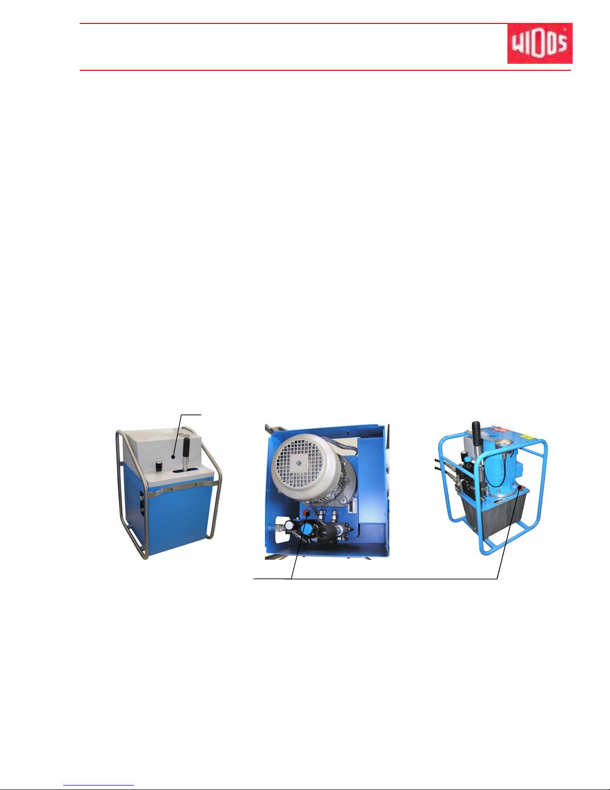
Kunststoff schweißtechnik
Maintenance, care and repair Chapter 9
16.01.12 Working Instructions WIDOS 20000 Page 58 of 98
9.2. Storage
• The cylindrical waves of the basic machine are to be kept free from dirt and need to be
covered with a thin oil film if they are not being used.
• Store dry.
9.3. Clamping elements
• For a long service life clean and grease regularly the threaded spindles and the joint parts
which are used for clamping the pipes.
9.4. How to clean the machine
The used material and substances for cleaning the machine are to be properly handled and
disposed of, especially:
• Upon cleaning with solvents.
• Upon lubricating with oil and grease.
9.5. How to check the hydraulic oil level for welding
Prior to each starting of the machine check oil level of the hydraulic unit in order to avoid
damages.
• Detach the upper cap at the enclosed hydraulic aggregate.
• Detach the red cover screw with oil dipstick.
• Clean the oil dipstick with a dry cloth and insert it again in the tank by screwing.
• Remove the oil dipstick again and check the oil level.
• The oil level must be between the two marks.
• If the oil level is under the lower mark, then hydraulic oil of the quality HLDP 35 must be
added.
• The oil level may not be above the upper mark since otherwise there is the danger of
spilling in certain situations.
Upper cap
Oil dipstick and
oil filler neck
Page 60
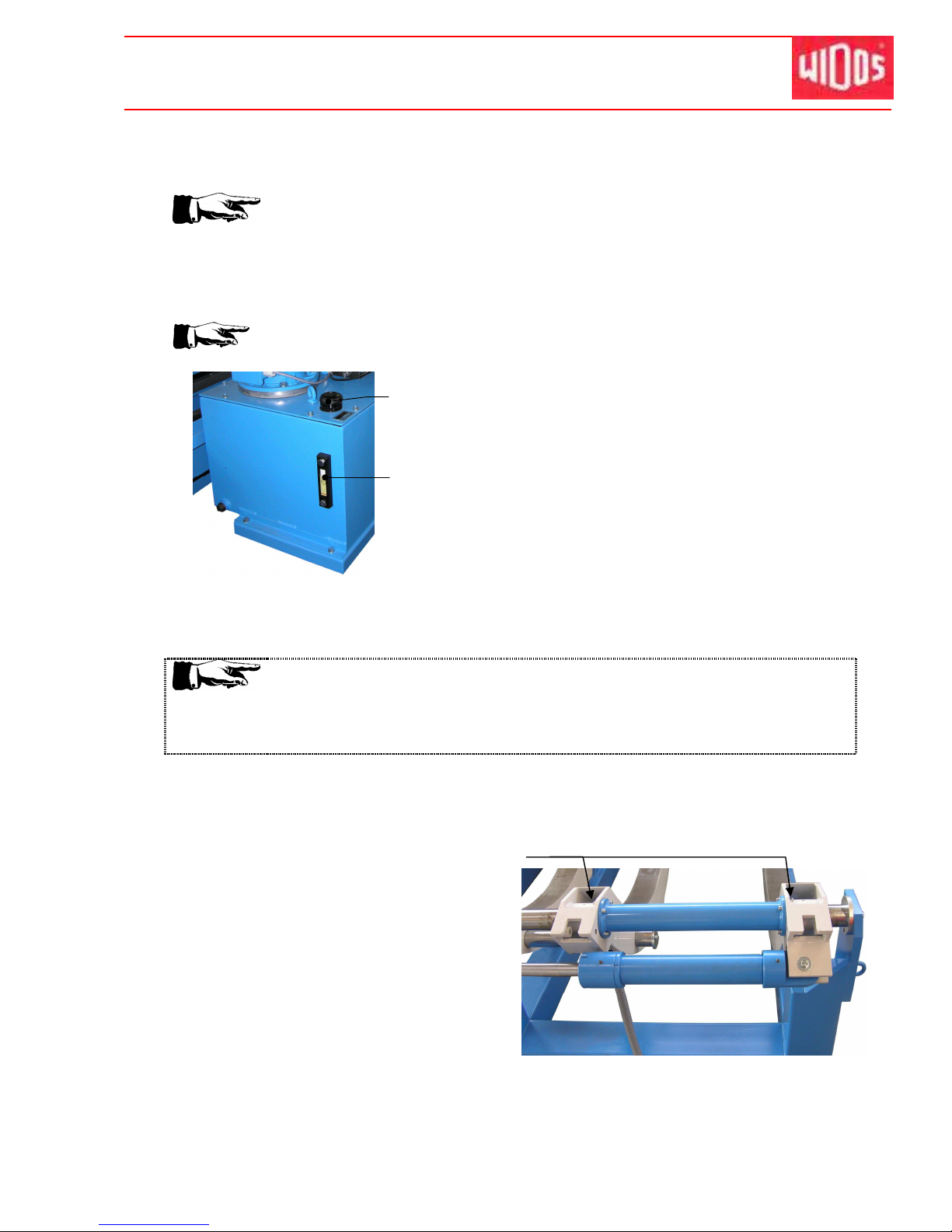
Kunststoff schweißtechnik
Maintenance, care and repair Chapter 9
16.01.12 Working Instructions WIDOS 20000 Page 59 of 98
• After having completed all work, tightly shut cap again.
• Mount the upper cap back onto the aggregate.
Do not incline the hydraulic unit since the cap of the hydraulic tank is not 100%
leakproof and oil may leak.
9.6. How to check the hydraulic oil level / refilling
Check the oil level every day before you activate the crane.
There is an inspection glass at the front of the hydraulic
oil tank.
The oil level (A) must absolutely be over the lower red
mark and somewhere in the center of the inspection
glass.
If necessary refill oil into the oil filler neck (B) of the tank.
Afterwards necessarily shut the cap again.
9.7. Used hydraulic oil
Only use HLPD 35.
Features: protection against corrosion, resistance to ageing, abrasionreducing additives,
high carrying capacity and particularly water-repellent.
The hydraulic oil has to be disposed of properly.
9.8. How to lubricate the guide rods
Grease nipples are mounted to the flexible lower
parts of the clamping rings.
In order to warrant a long durability, you should
lubricate the guide rods if necessary via these
grease nipples.
B
A
Page 61
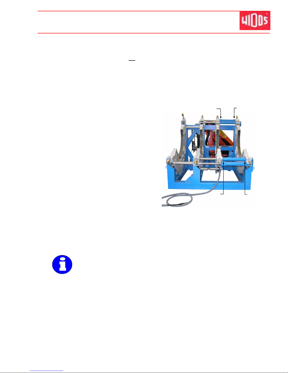
Kunststoff schweißtechnik
Maintenance, care and repair Chapter 9
16.01.12 Working Instructions WIDOS 20000 Page 60 of 98
9.9. How to vent the hydraulic cylinders
• Venting the hydraulic cylinder is not required, if
- the hoses have been disconnected from the quick-action couplings at the control unit
because the remaining oil in the hose is being kept by valves and for this reason no air
can enter.
• The hydraulic cylinder must be vented if
-
There has been too less oil in the tank and air has been attracted.
-
There were leaky spots at the hoses or in the connections.
-
The hoses were unscrewed from the basic machine.
• Eliminate the cause of the air entrance.
• Open the machine completely.
• First unscrew the lower „vent screw (Z1) for
closing“.
• Connect the transparent venting hose and
insert it in the collecting vessel of the
aggregate.
• Close until there is no more air visible in the
venting hose, then tighten again the vent
screw.
• Close the machine completely.
• Unscrew the lower „vent screw (A1) for
opening“(right-hand side).
• Connect the transparent venting hose and
insert it in the collecting vessel of the
aggregate.
• Open until there is no more air visible in the venting hose, then tighten again the vent
screw.
• When the venting process at the lower vent screws is completed, repeat the process at the
upper „vent screw (Z2) for closing“ (left-hand side), as well as at the upper „vent screw (A2)
for opening“ (right-hand side).
The lower vent screws always have to be vented at first because there is a
direct connection between the upper and the lower cylinders.
• If air remains in the lower cylinder, it will ascend in the upper cylinder when
pressure is applied.
There must always be enough oil in the tank.
Z2
A2
Z1
A1
Page 62
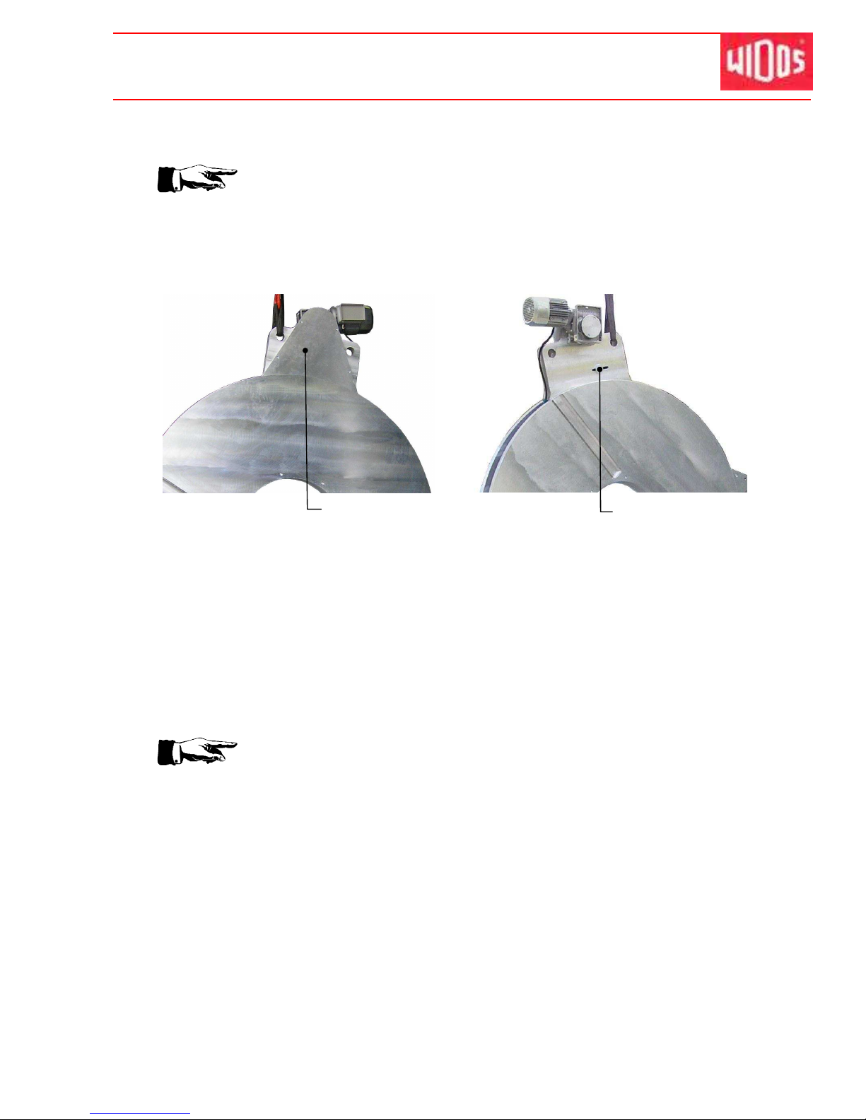
Kunststoff schweißtechnik
Maintenance, care and repair Chapter 9
16.01.12 Working Instructions WIDOS 20000 Page 61 of 98
9.10. Planer
Do not discard the planer on its blades, always put it into the reception box.
• Check the stress of the drive chain in the planer and grease it regularly.
Unscrew the cap of the planer housing on the opposite side of the planer motor, detach the
chain tensioner and shift in the oblong hole until the chain is (hand-tight) clamped. Screw
cap again.
• Check the blades of the planer for sharpness, turn them if necessary (grinded on both
sides, max. thickness of the shavings: 0,2 mm.
9.11. Protect machine parts against corrosion
In case of air humidity of > 85% and / or high temperatures you must treat the untreated steel
parts of the machine with anti-corrosive protecting agent (e.g. AVILUB NCI 9840).
9.12. Disposal
At the end of the life time, the machine has to be disposed of properly,
non-polluting and in accordance with the national laws of waste disposal.
Cover
Chain tensioner
Page 63
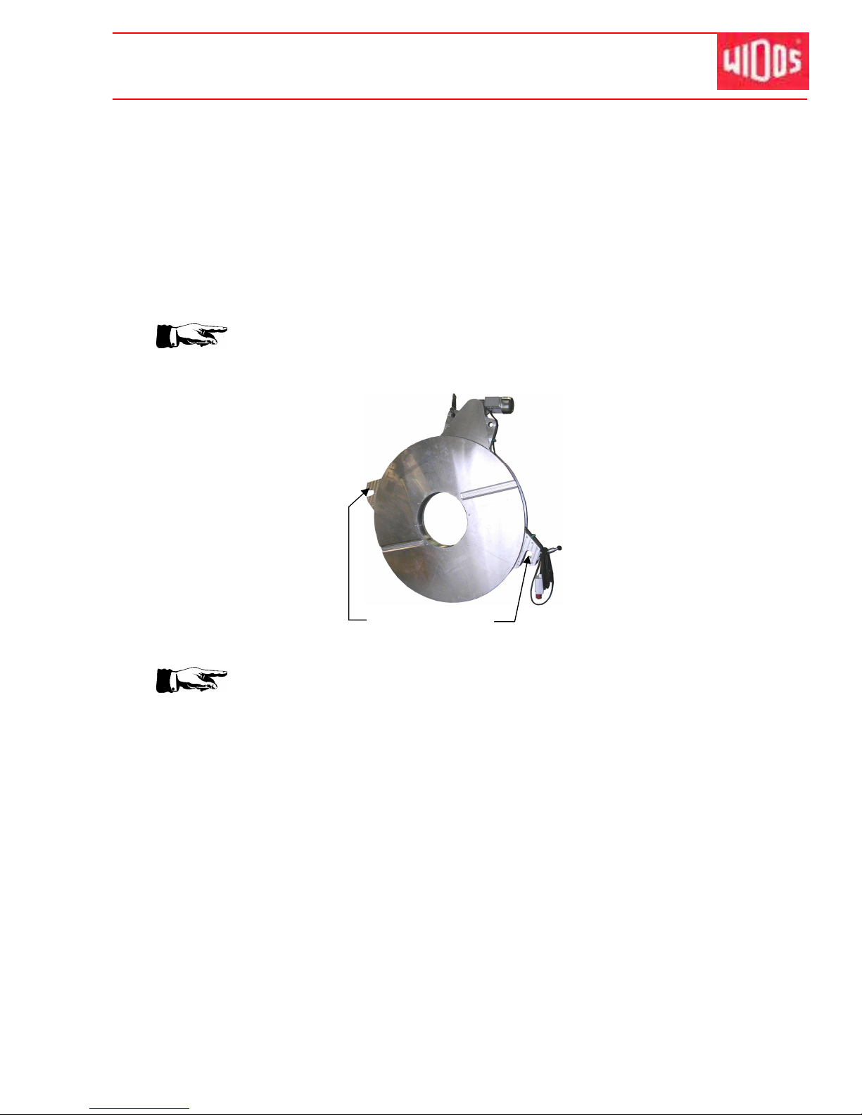
Kunststoff schweißtechnik
WIDOS Einsteinstr. 5 Phone ++49 7152 9939 - 0
W. Dommer Söhne GmbH D-71254 Ditzingen-Heimerdingen Fax ++49 7152 9939 - 40
16.01.12 Working Instructions WIDOS 20000 Page 62 of 98
10. Transport
• The hydraulic hoses at the basic machine should not be detached (air penetration).Make
sure that they are not crushed.
• Do not tilt the aggregate too much. Otherwise there is the danger that oil may come out
• Protect the machine from heavy shocks.
• Handle the machine carefully. Take much care when using automatic handling and carrying
machines.
Transport the planer hinged or in the reception box.
If the planer is transported in the basic machine grease the holders with PTFEspray because otherwise damages at the drag rod may occur.
Transport the heating element hinged or in the reception box.
Never discard the heating element onto is coated surfaces, the coating must be
undamaged in the welding area!
Grease the holders
Page 64
Kunststoff schweißtechnik
WIDOS
Einsteinstraße 5 Telefon +49 (0) 71 52 / 99 39 - 0
W. Dommer Söhne GmbH D-71254 Ditzingen-Heimerdingen Telefax +49 (0) 71 52 / 99 39 - 40
[email protected] Internet: www.widos.de
16.01.12 W orking Instructions WIDOS 20000 Page 63 of 98
11. Hydraulic and electric diagrams
11.1. Electric diagram with enclosed hydraulic aggregate
Page 65
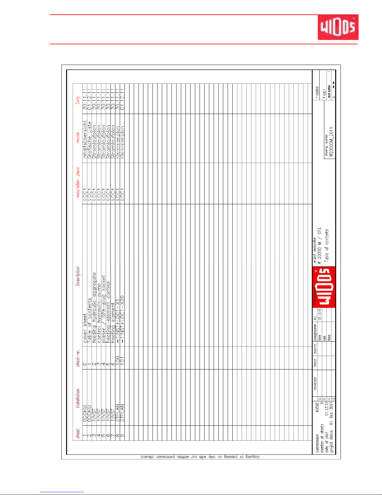
Kunststoff schweißtechnik
Hydraulic and electric diagrams Chapter 11
16.01.2012 Working Instructions WIDOS 20000 Page 64 ofd 98
Page 66
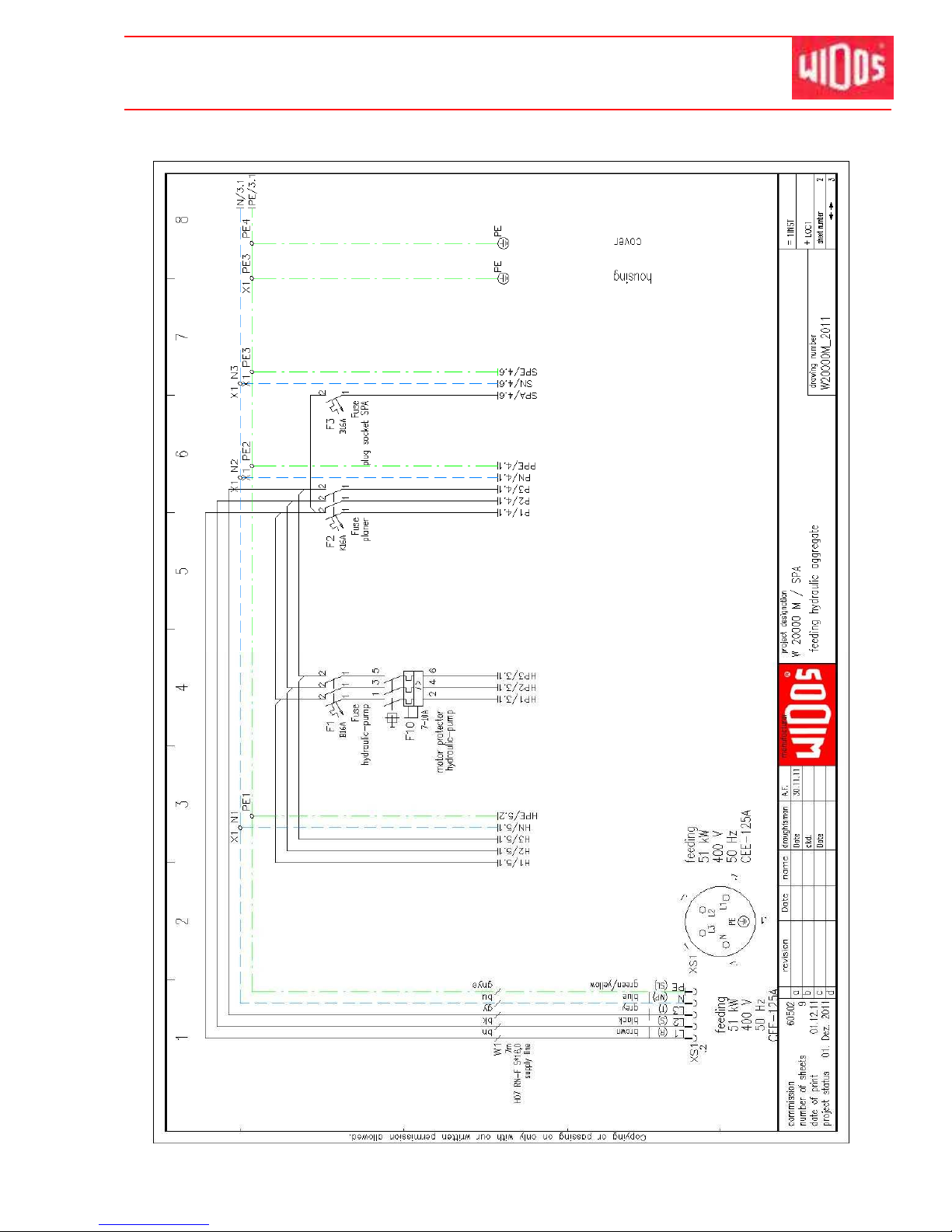
Kunststoff schweißtechnik
Hydraulic and electric diagrams Chapter 11
16.01.2012 Working Instructions WIDOS 20000 Page 65 ofd 98
Page 67
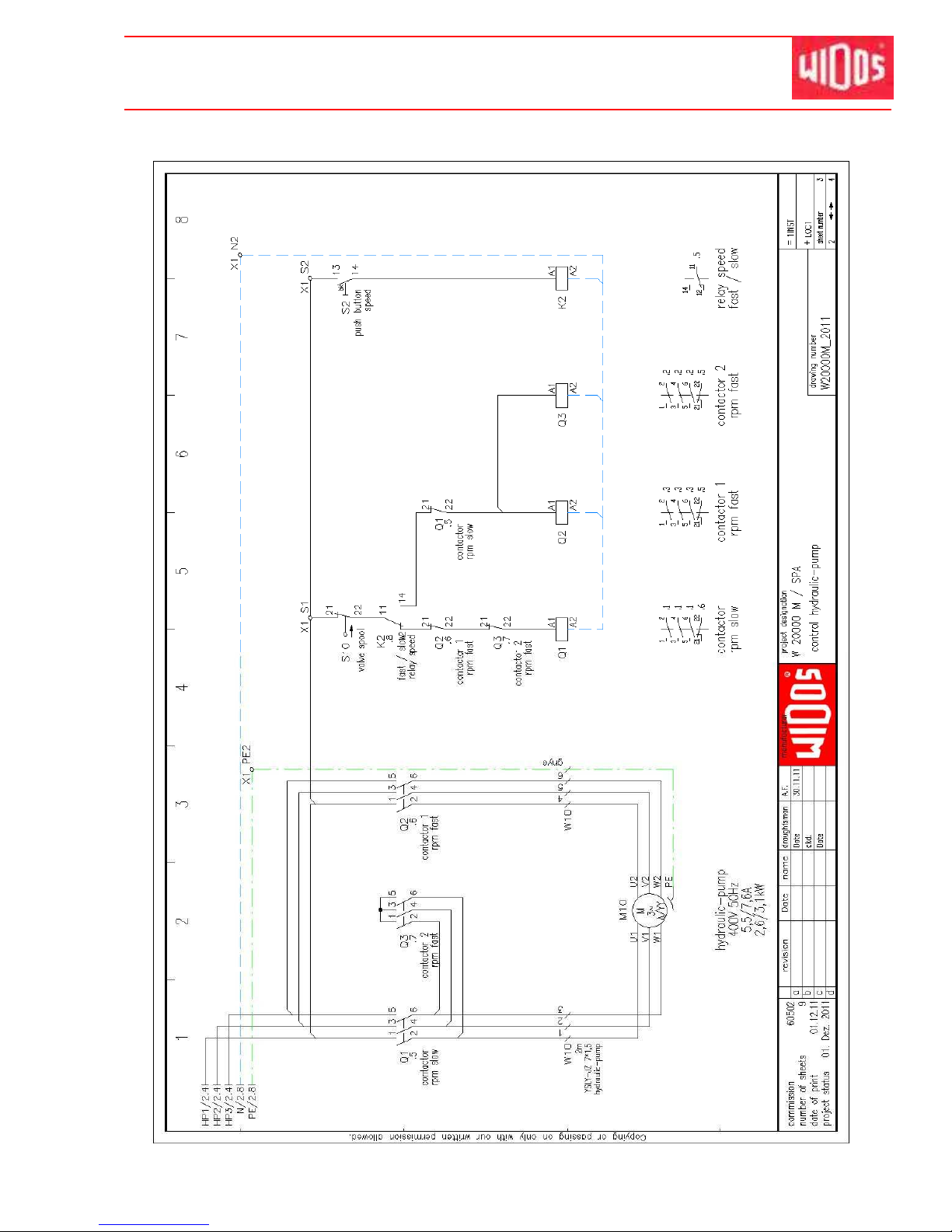
Kunststoff schweißtechnik
Hydraulic and electric diagrams Chapter 11
16.01.2012 Working Instructions WIDOS 20000 Page 66 ofd 98
Page 68
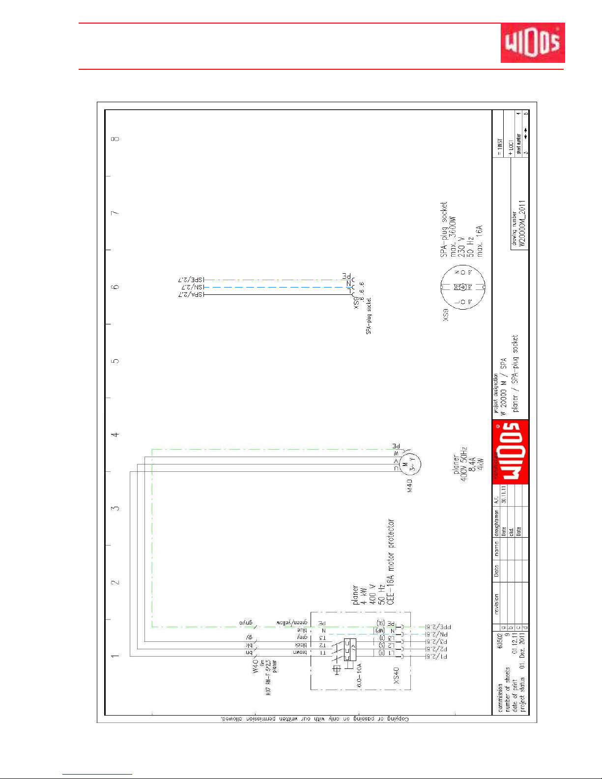
Kunststoff schweißtechnik
Hydraulic and electric diagrams Chapter 11
16.01.2012 Working Instructions WIDOS 20000 Page 67 ofd 98
Page 69
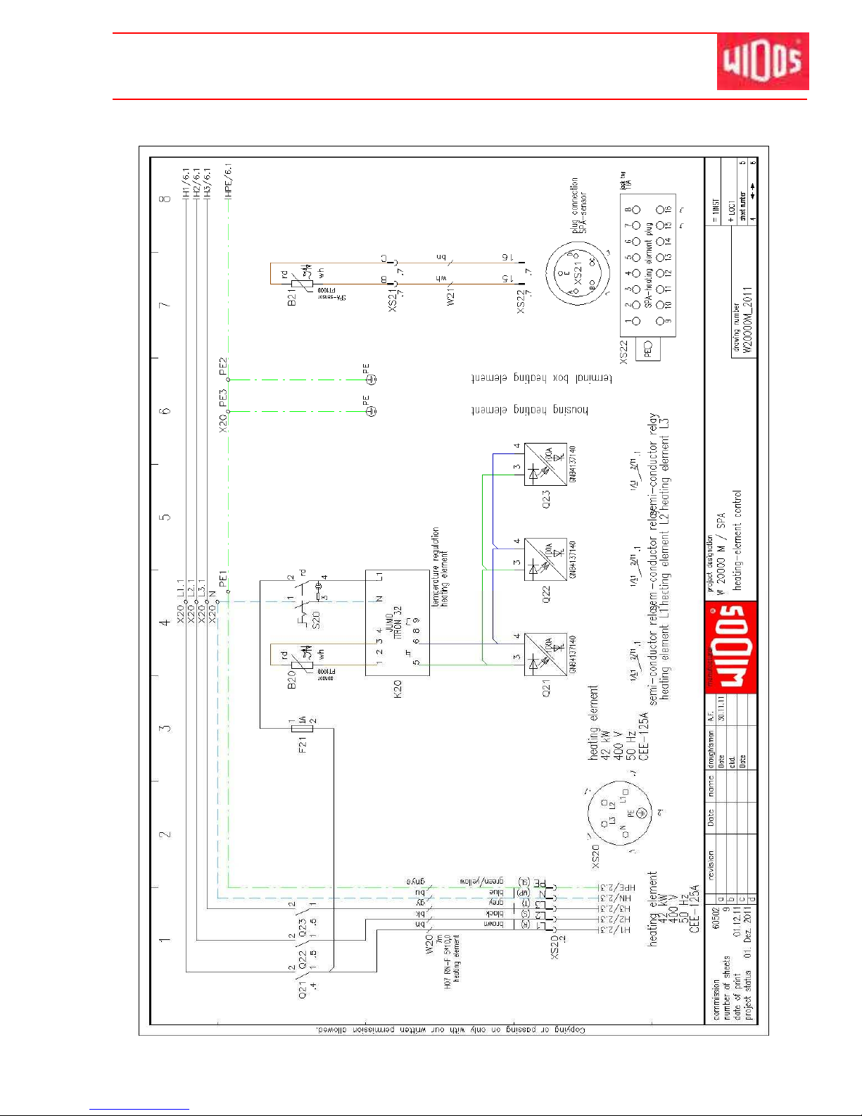
Kunststoff schweißtechnik
Hydraulic and electric diagrams Chapter 11
16.01.2012 Working Instructions WIDOS 20000 Page 68 ofd 98
Page 70
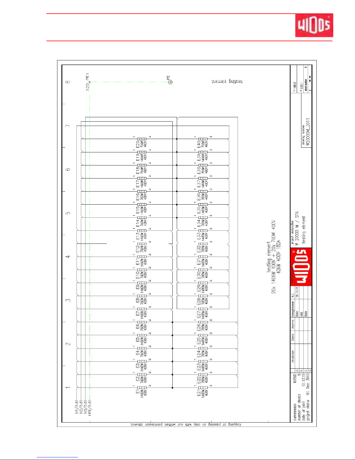
Kunststoff schweißtechnik
Hydraulic and electric diagrams Chapter 11
16.01.2012 Working Instructions WIDOS 20000 Page 69 ofd 98
Page 71
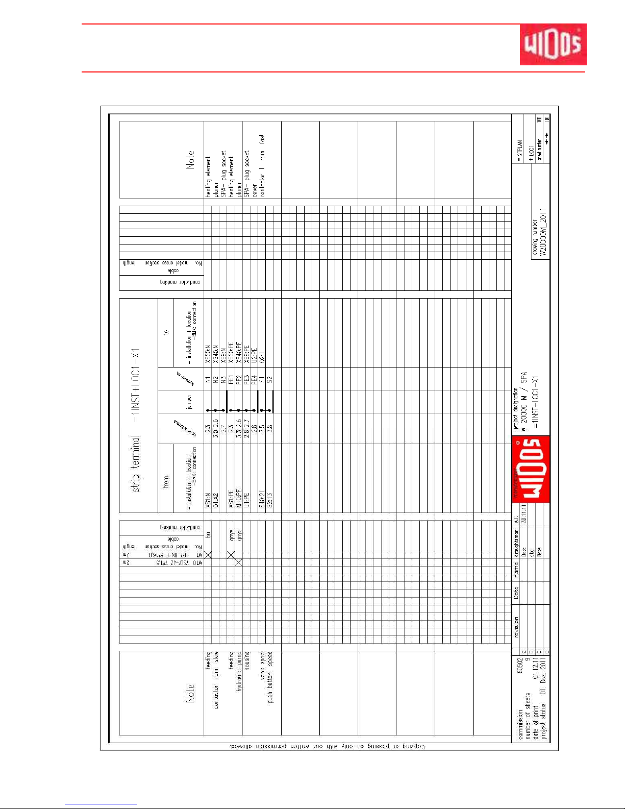
Kunststoff schweißtechnik
Hydraulic and electric diagrams Chapter 11
16.01.2012 Working Instructions WIDOS 20000 Page 70 ofd 98
Page 72
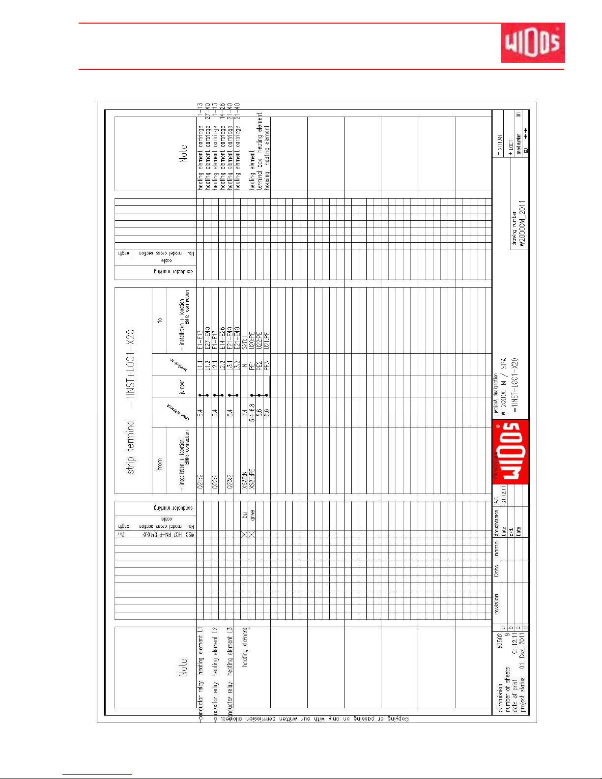
Kunststoff schweißtechnik
Hydraulic and electric diagrams Chapter 11
16.01.2012 Working Instructions WIDOS 20000 Page 71 ofd 98
Page 73
Kunststoff schweißtechnik
Hydraulic and electric diagrams Chapter 11
16.01.2012 Working Instructions WIDOS 20000 Page 72 ofd 98
11.2. Electric diagram with naked hydraulic aggregate
Page 74
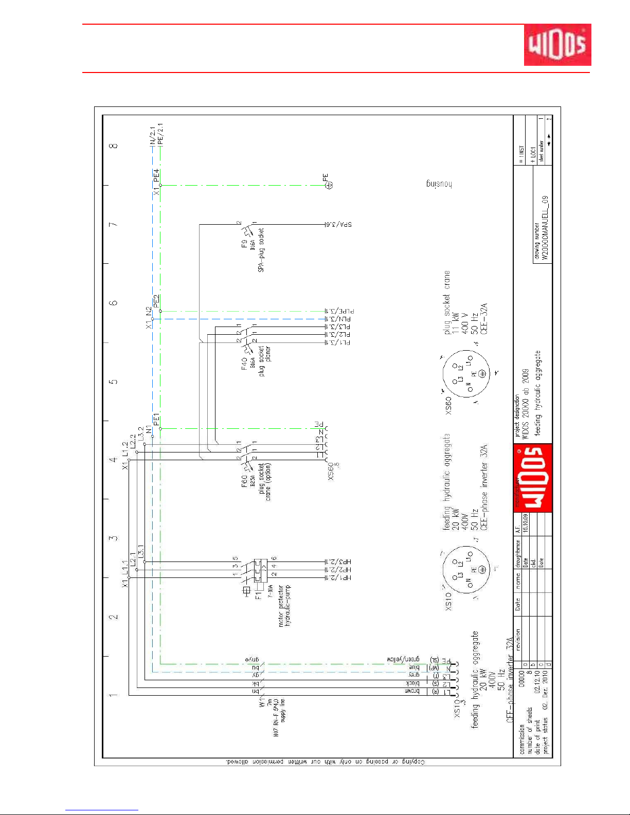
Kunststoff schweißtechnik
Hydraulic and electric diagrams Chapter 11
16.01.2012 Working Instructions WIDOS 20000 Page 73 ofd 98
Page 75
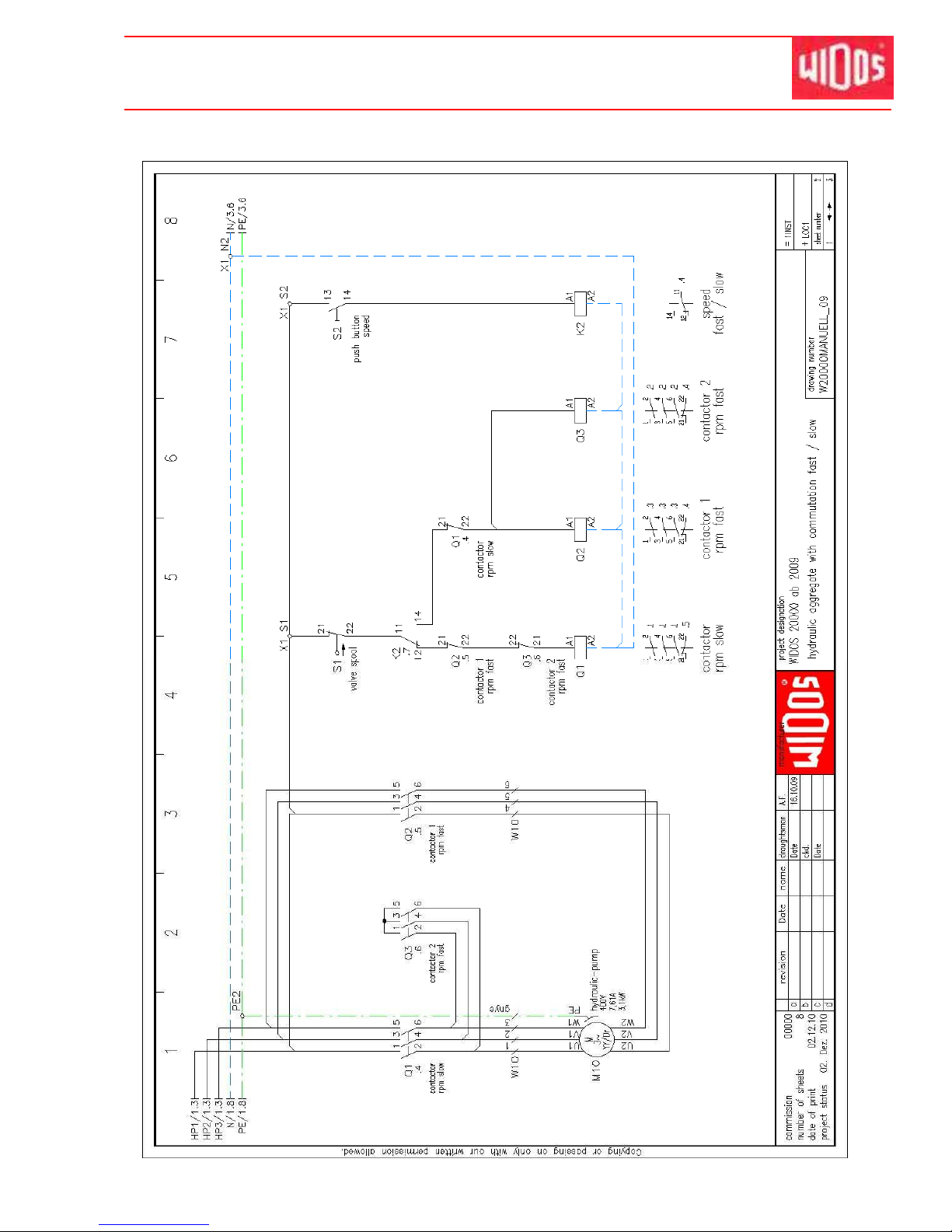
Kunststoff schweißtechnik
Hydraulic and electric diagrams Chapter 11
16.01.2012 Working Instructions WIDOS 20000 Page 74 ofd 98
Page 76
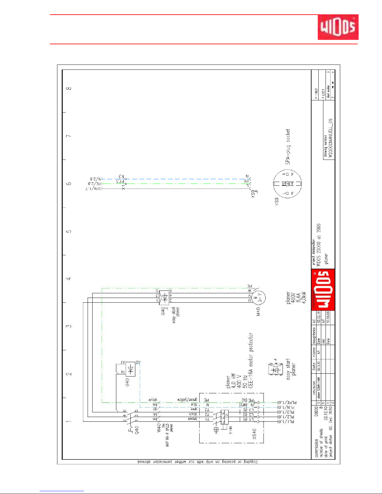
Kunststoff schweißtechnik
Hydraulic and electric diagrams Chapter 11
16.01.2012 Working Instructions WIDOS 20000 Page 75 ofd 98
Page 77
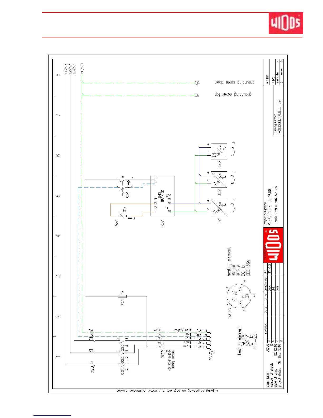
Kunststoff schweißtechnik
Hydraulic and electric diagrams Chapter 11
16.01.2012 Working Instructions WIDOS 20000 Page 76 ofd 98
Page 78
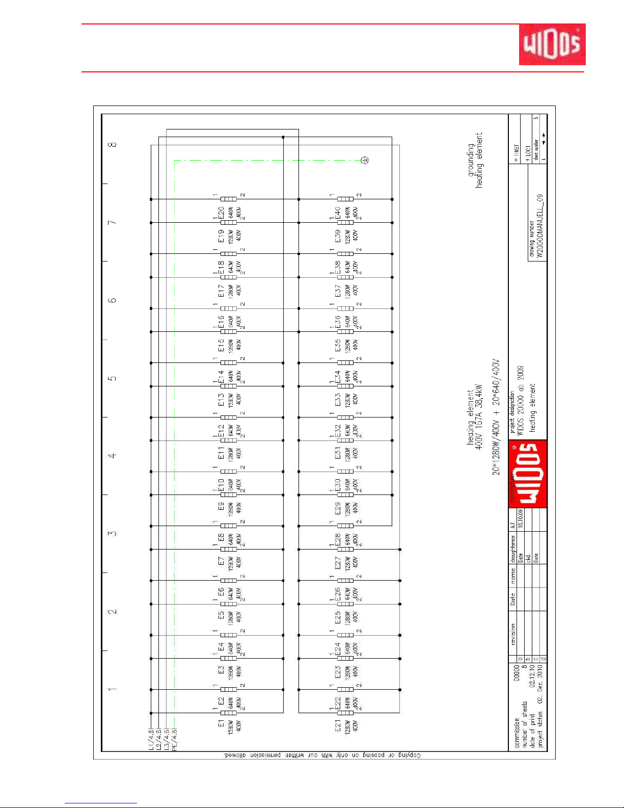
Kunststoff schweißtechnik
Hydraulic and electric diagrams Chapter 11
16.01.2012 Working Instructions WIDOS 20000 Page 77 ofd 98
Page 79
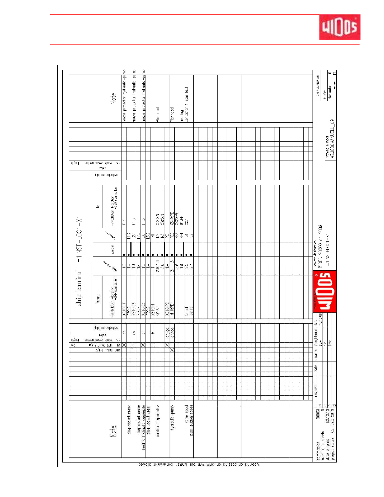
Kunststoff schweißtechnik
Hydraulic and electric diagrams Chapter 11
16.01.2012 Working Instructions WIDOS 20000 Page 78 ofd 98
Page 80
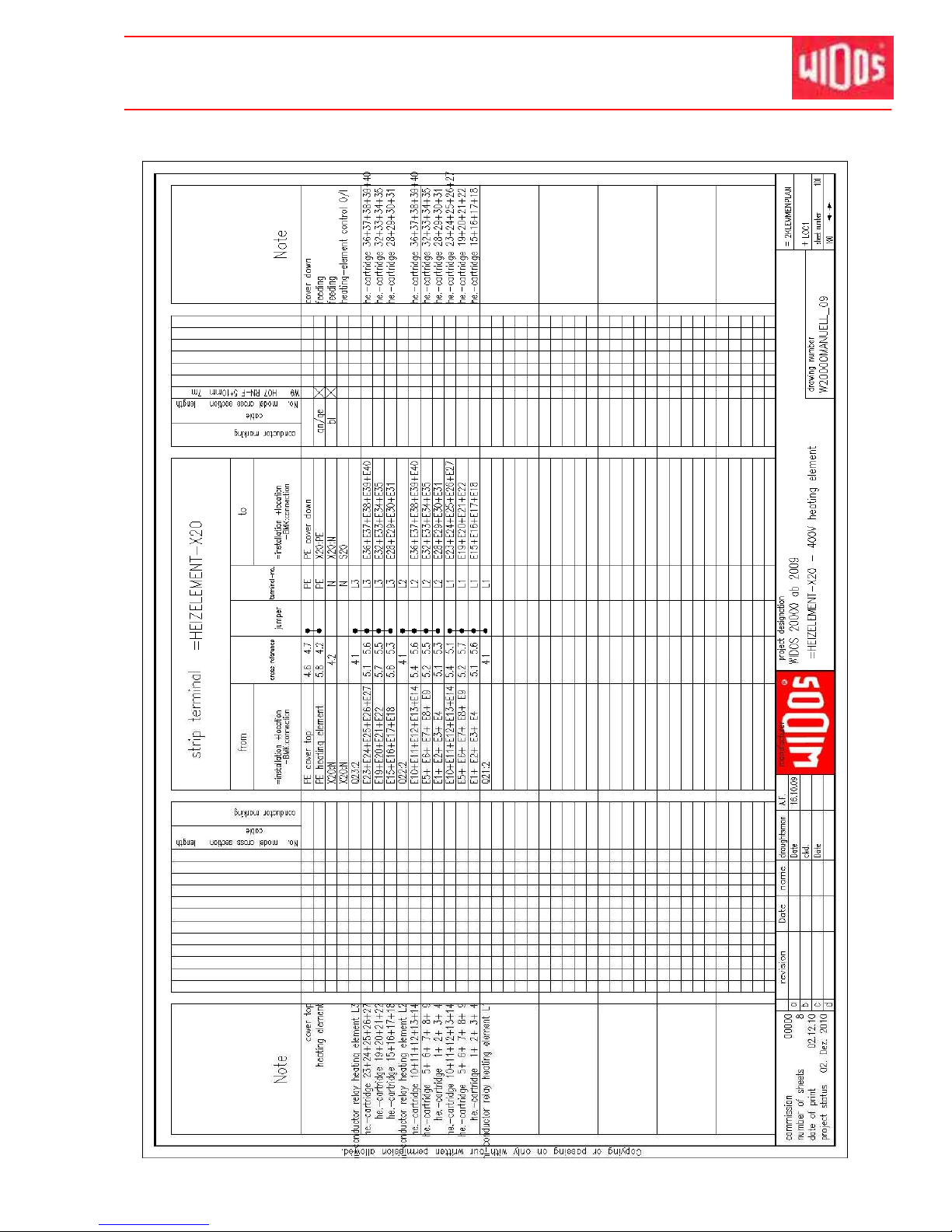
Kunststoff schweißtechnik
Hydraulic and electric diagrams Chapter 11
16.01.2012 Working Instructions WIDOS 20000 Page 79 ofd 98
Page 81
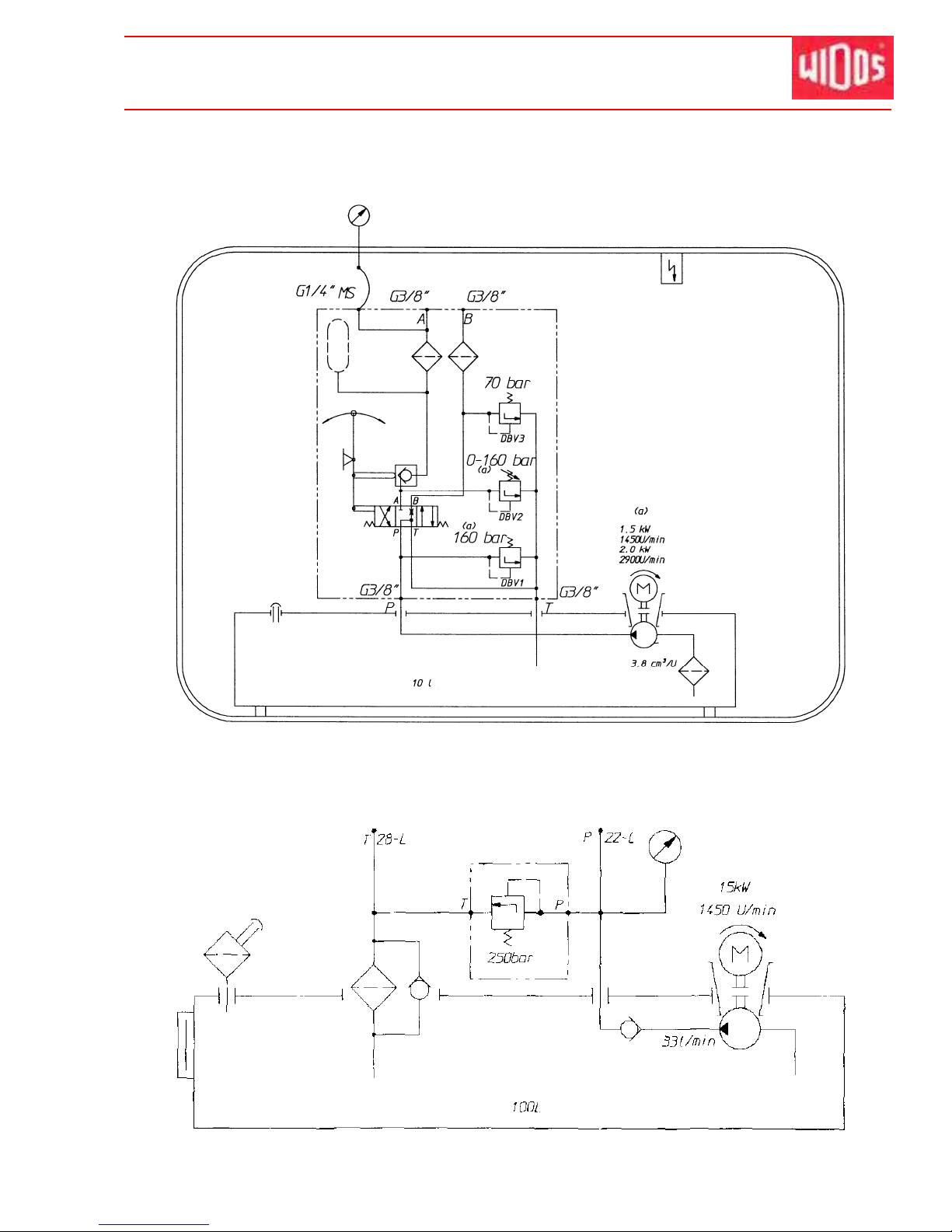
Kunststoff schweißtechnik
Hydraulic and electric diagrams Chapter 11
16.01.2012 Working Instructions WIDOS 20000 Page 80 ofd 98
11.3. Hydraulic diagram for welding aggregates
11.4. Hydraulic diagram for crane aggregat:
Page 82
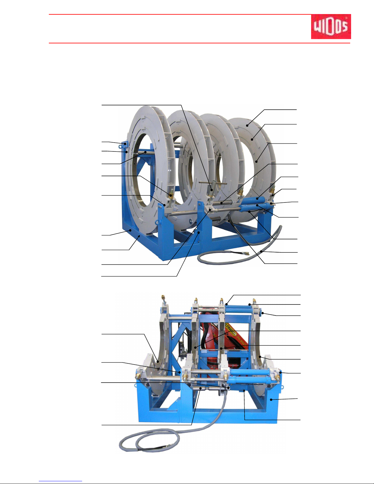
Kunststoff schweißtechnik
WIDOS
Einsteinstraße 5 Telefon +49 (0) 71 52 / 99 39 - 0
W. Dommer Söhne GmbH D-71254 Ditzingen-Heimerdingen Telefax +49 (0) 71 52 / 99 39 - 40
[email protected] Internet: www.widos.de
16.01.12 W orking Instructions WIDOS 20000 Page 81 of 98
1
6
14 - 16
41
51
28 - 30
7 - 9
24 - 25
39 - 40
20
13
42
2 - 3
12
36
46
47
48
10 - 11
35
31
32 - 33
34
43
17 - 18
37 - 38
19
23
4 - 5
21 - 22
44 - 45
49 - 50
52-54
26 - 27
12. Spare parts list
12.1. Basic machine
Page 83

Kunststoff schweißtechnik
Spare parts list Chapter 12
Basic machine
WIDOS 20000
Pos. Name Piece Article no.
1 Socket spanner SW 65 1 ZRS65
2 Hexagon-head screw M 16x60 DIN 933 2 0933P060
3 Washer M 16 DIN 125 2 0125P
4 Hexagon-head screw M 20x40 DIN 933 6 0933T040
5 Washer M 20 DIN 9021 6 9021T
6 Distance shaft clamping ring, fixed 3 2291639
7 Thread spindle 8 22914192
8 Disc 8 22914202
9 Spindle nut TR 40x7 8 22914212
10 Riveted bolt for spindle 8 22914101
11 Flat-head screw M 12 x 30 DIN 7991va 16 7991L030VA
12 Support in front 1 2291627
13 Pan-head screw M 16x25 DIN 912 6 0912P025
14 Bolt for rod end bearing 2 2291609
15 Hexagon head screw M 16x20 DIN 933 4 0933P020
16 Washer M 16 DIN 9021 4 9021P
17 Hexagon-head screw M 20x60 DIN 933 12 0933T060
18 Washer M 20 DIN 125 12 0125T
19 Upper clamping tool 4 2291635
20 Reducer insert OD1800 to 2000mm 8 22984180
-- Reducer insert OD1600 to 2000mm 8 22984160
21 Reducer insert OD1400 to 1600mm 8 22984140
-- Reducer insert OD 1200 to 1600mm 8 22984120
22 Pan-head screw M 16x60 DIN 912 (OD 1200 - 1800mm 16 0912P060
23 Guide shaft 2 2291637
24 Guide tube 2 2291638
25 Guide bushing 8 L809090AMS
26 Distance bushing for grease nipple 4 22916382
27 Grease nipple M 6x1 4 J0900
28 Bolt for rod end bearing 2 2291609
29 Washer M 16 DIN 9021 4 9021P
30 Hexagon head screw M 16x20 DIN 933 4 0933P020
31 Hydraulic cylinder ZU 250-Si-g 80/500 D 90° 2 2291636
32 Hydraulic hose, below short 1 on request
33 Hydraulic hose, below long 1 on request
34 Protection hose complete 1 on request
-- Hydraulic hose (5 m) 2 VSCHL97
-- Casing 1 EA0801
-- Coupling box, flat sealing 1 VMU14
-- Coupling plug, flat sealing 1 VST14
-- Bolting 2 VXGE12L14
-- Compressed bushing 4 on request
-- Sealing nipple 2 on request
16.01.2012 Working Instructions WIDOS 20000
Page 82 / 1 of 98
Page 84

Kunststoff schweißtechnik
Spare parts list Chapter 12
Basic machine
WIDOS 20000
Pos. Name Piece Article no.
-- Bow-shaped nipple 2 VP3810R11
35 T-piece 2 VT12LR
36 Outer clamping tool, fixed 1 2291631
37 Hexagon-head screw M 20x80 DIN 933 4 0933T080
38 Washer M 20 DIN 125 4 0125T
39 Disc for tear-off bar 2 2291619
40 Hexagon-head screw M 16x30 DIN 933 2 0933P030
41 Tear-off bar for heating element 1 2291618
42 Upper hydraulic hose, short 1 on request
43 Upper hydraulic hose, long 1 on request
44 Hexagon-head screw M 20x60 DIN 933 2 0933P06T0
45 Washer M 20 DIN 125 2 0125T
46 Inner clamping tool, fixed lower part 1 2291632
47 Inner clamping tool, movable lower part 1 2291633
48 Outer clamping tool, movable lower part 1 2291634
49 Reinforcement for guiding shaft 2 2261614
50 Pan-head screw M 12x40 DIN 7984 6 7984L040
51 Base frame 1 2291626
52 Distance shaft, clamping ring, movable 1 22916392
53 Hexagon-head screw M 20x40 DIN 933 2 0933T040
54 Washer M 20 DIN 9021 2 9021T
16.01.2012 Working Instructions WIDOS 20000
Page 82 / 2 of 98
Page 85
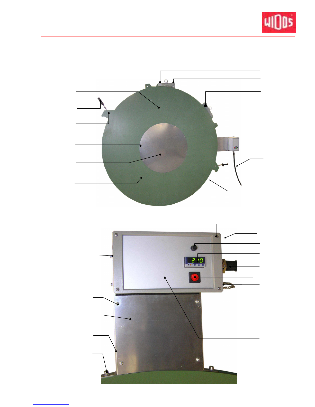
Kunststoff schweißtechnik
Spare parts list Chapter 12
16.01.12 W orking Instructions WIDOS 20000 Page 83 of 98
12.2. Heating element
(Terminal box front view)
1
4
5 - 6
7
2 - 3
8 - 11
14 - 15
31 - 32
28 - 29
23 - 25
36
33 – 34
35
37
30
20 - 22
16 - 17
40 - 49
26
13
27
38 - 39
12
18 - 19
Page 86

Kunststoff schweißtechnik
Spare parts list Chapter 12
Heating element
WIDOS 20000
Pos. Name Piece Article no.
1 Heating element complete 1 on request
Heating plate new 1 2295440
2 Handle 2 H0205
3 Handlebar for heating element 2 2265143
4 Locking handle 2 2265142
5 Flat-head screw M 8 xx30 DIN 7991va 12 7991H030va
6 Cap nut M 10 x 20 12 on request
7 Cover for heating plate 2 2295144
8 Temperature probe PT 1000 2 on request
9 Heating cartridge compl.,Ø16x650 / 1400 W / 400 V 20 H2223
10 Heating cartridge compl.,Ø16x325 / 700 W / 400 V 20 H2224
11 Distance bushing for short cartridges 20 2295149
12 Pan-head screw M 16 x 40 DIN 912 4 0912P040
13 Pan-head screw M 16 x 65 DIN 912 4 0912P065
14 Suspension 2 2295444
15 Locking bolt for suspension 4 2295443
16 Connecting cable 10 m EL025100
17 Plug 125A 1 EST01125
18 Pan-head screw M 4x10 DIN 912 31 0912D010
19 Wascher M 5 DIN 9021 2 9021E
20 Pan-head screw M 6 x 20 DIN 912 4 0912F020
21 Nut M 6 DIN 934 4 0934F
22 Washer M 6 DIN 9021 4 9021F
23 Distance bushing 4 on request
24 Washer M 6 8 ROSM6
25 Lens-head screw M 6 x 20 DIN 7380 8 7380F020
26 Cover for frame 2 2295147
27 Mounting for terminal box 1 2265148
28 Pan-head screw M 8x120 DIN 912 2 0912H120
29 Wascher M 8 DIN 127 2 0127H
30 Lens head screw M5x20 DIN 7991 8 0966E020
31 Heat sink 1 2295416
32 Pan-head screw M 5 x 18 DIN 84 6 0084F018
33 Fuse 1 ESI001
34 Holder for fuse 1 ESI003
35 Temperature regulator 1 H6204
36 Bolting HKL 1 EVH21322925
37 Rocker switch, red 1 H0903
38* flange socket, 4-pole 1 EST0548
39* Cover 1 EST0508
16.01.2012 Working Instructions WIDOS 20000 Page 84 1 of 98
Page 87
Kunststoff schweißtechnik
Spare parts list Chapter 12
Heating element
WIDOS 20000
Pos. Name Piece Article no.
40 Terminal box for heating element 1 2295407
41 Housing for terminal box 1 22954071
42 Bottom for terminal box 1 22954073
43 Bottom frame for terminal box 1 22954072
44 Cover for terminal box 1 22954074
45 Semiconductor relay 3 ES20010
46 Top-hat rail, perforated 1 m EA0105
47 Porcelain terminal clamp 6 EA1006
48 Bushing clamp 4 EA11116
49 Grounded conductor clamp 1 EA11410
-- Steel wire with hook 1 J9994
--* Cable for temperature probe for SPA 1 on request
--* Line adaptor, heating element SPA 600 complete 1 E97230
*Only with optional SPA-600
16.01.2012 Working Instructions WIDOS 20000 Page 84 2 of 98
Page 88
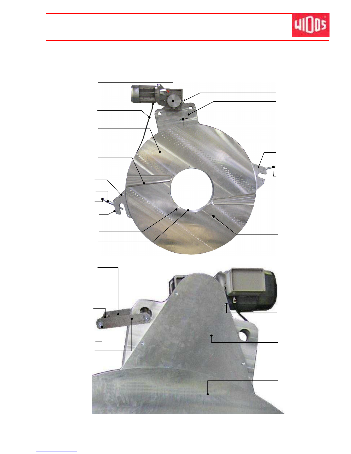
Kunststoff schweißtechnik
Spare parts list Chapter 12
16.01.12 W orking Instructions WIDOS 20000 Page 85 of 98
12.3. Planer
49
9 - 12
1 - 2
13
17
45 - 47
5
3 - 4
6 - 8
50
15 - 16
43 - 44
22 - 31
33 - 38
18 - 21
48
32
39 - 42
14
51
52
54
53
Page 89

Kunststoff schweißtechnik
Spare parts list Chapter 12
Planer
WIDOS 20000
Pos. Name Piece Article No.
1 Cover for geared motor 1 145425
2 Pan-head screw M12x20 DIN 912 2 0912L020
3 Connecting cable 1 EL02525
4 Protective motor plug 16 A 1 EST0562
5 Planer disc, right-hand 1 2294402
6 Blade 170 mm 16 MES170
7 Flat-head screw M 3x8 DIN 965 96 0965C008
8 Washer 16 MU170
9 Frontal reinforcement plate, left 1 22944012
10 Frontal reinforcement plate, right 1 22944014
11 Pan-head screw M12x50 DIN 912 10 0912L050
12 Cylinder pin 12x60 DIN 6325 2 6325L
13 Guide for planer locking complete 1 2294410
14 Ball button C 40 DIN 319 1 0319C40
15 Pan-head screw M 12x35 DIN 912 6 0912L035
16 Washer M 12 DIN 125 6 0125L
17 Pan-head screw M 12x50 DIN 912 16 0912L050
18 Intermediate ring for planer discs 1 22944032
19 Four point bearing VLU 200944 1 L200944
20 Chain wheel (1 1/4" x 3/4", 114 teeth) 1 2294408
21 Flat-head screw M 12x30 DIN 7991 8 7991L030
22
Driving wheel (1 1/4
"
x 3/4", Z=15)
1 2294405
23 Disc for driving wheel 1 250410
24 Flat-head screw M10x16 DIN 7991 1 7991J016
25 Geared motor (4 kW, 400 V, 20:1) 1 on request
26 Pan-head screw M 12x30 DIN 912 4 0912L030
27 Drive shaft 1 2294609
28 Fitted key A 12x8x125 DIN 6885 1 6885L125
29 Fitted key A 10x8x25 DIN 6885 1 6885J025
30 Disc for plug-in shaft 1 250411
31 Hexagon-head screw M 10x25 DIN 933 1 0933J025
32 Planer holder 1 2294401
33 Locking ring size 17 DIN 471 1 0471Q
34 Bolt for chain tensioner 1 2294407
35 Tension wheel (1 1/4" x 3/4", Z=12 teeth) 1 2294406
36 Ball bearing 2 L6003Z
37 Washer M16 DIN 6340 1 6340P
38 Locking nut M 16 DIN 985 1 0985P
39 Rear reinforcementn plate, left 1 22944011
40 Rear reinforcementn plate, right 1 22944013
41 Pan-head screw M12x50 DIN 912 10 0912L050
42 Cylinder pin 12x60 DIN 6325 2 6325L
43 Ball button C 40 DIN 319 1 0319C40
16.01.2012 Working Instructions WIDOS 20000 Page 86 / 1 of 98
Page 90
Kunststoff schweißtechnik
Spare parts list Chapter 12
Planer
WIDOS 20000
Pos. Name Piece Article No.
44 Handlebar 1 2294413
45 Chain without joint (1 1/4", 159 chain links) 1 on request
46 Chain link cranked (1 1/4" Z=12) 1 on request
47 Chain joint (1 1/4") 1 on request
48 Suspension for planer complete 1 2294409
49 Bolt for suspension 2 22944092
50 Flat-head screw M 10x30 DIN 7991 4 7991J030
51 Guide rail for suspension 2 22944091
52 Pan-head screw M 8x30 DIN 912 4 0912H030
53 Cap for planer holder 1 2294404
54 Planer disc, left-hand 1 2294403
16.01.2012 Working Instructions WIDOS 20000 Page 86 / 2 of 98
Page 91
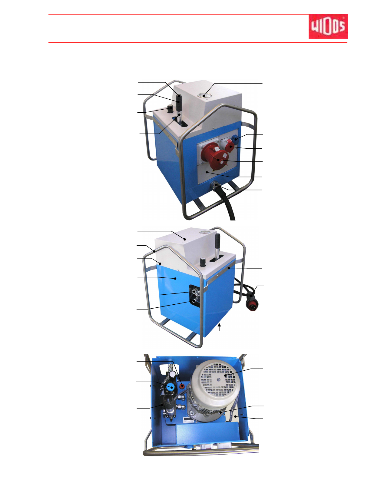
Kunststoff schweißtechnik
Spare parts list Chapter 12
16.01.12 W orking Instructions WIDOS 20000 Page 87 of 98
12.4. Hydraulic aggregate, enclosed (optional)
32
33 - 38
28
31
16
20
18
19
21
24 - 25
26 - 27
17
22 - 23
2
3
7 - 9
15
11
13 - 14
4 - 6
12
10
29 - 30
39
1
Page 92

Kunststoff schweißtechnik
Spare parts list Chapter 12
Hydraulic aggregate
WIDOS 20000
Pos. Name Piece Order no.
1 Press button 1 ES3801
2 Grip with thread 1 H09061
3 Button for pressure relief valve 1 101022
4 Grip for hydraulic aggregate 1 1060061
5 Skintop screwing M 12x1,5 1 EV1012
6 Hexagon nut M 10 DIN 935 1 0934J
7 Pressure gauge 0-100 bar 1 023004
8 Screwed connection for pressure gauge 1 V042314
9 Mini hose 1 V0400150
10 Isolated plug 230V 1 EST0705
11 CEE-electrical socket 400V / 16 A 1 EST16EG
12 CEE-electrical socket 125 A 1 EST125EG
13 Fitting panel 1 1060103
14 Lens-head screw M 5x16 DIN 7380 8 7380E016
15 HKL-screwing 1 EVH21252117
16 Cover plate for motor 1 1060111
17 Frame for hydraulic box 1 1060124
18 Lens-head screw M 5x10 DIN 7380 6 7380E010
19 Box for hydraulic box 1 1060102
20 Coupling sleeve, flat packed 2 VMU14
21 Coupling plug, flat packed 2 VST14
22 Lens-head screw M 5x10 DIN 7380 4 7380E010
23 Washer M5 DIN 125 4 0125E
24 Connecting cable H07 RN-F 5x16,0mm² 1 EL025160
25 Plug 125 A, phase converter 1 EST01125
26 Pan-head screw M 8x25 DIN 912 4 0912H025
27 Washer M8 DIN 125 4 0125H
28 Oil dip stick 1 1010212
29 Pressure accumulator 1 104206
30 Seal ring 1 D13,7x22
31 Valve box 1 on request
32 Pole changing switch for motor 1 ADP1060
33 Shaft adapter for engine 1 1060117
34 Hexagon nut M5 DIN 935 6 0934E
35 Washer M 5 DIN 125 6 0125E
36 Tank cap 1 233236
37 Oil tank 10 l 1 on request
38 Hydraulic pump 1 on request
39 Cover for hydraulic box 1 1060105
-- Plate "Release pressure" 1 SCHD-L
-- Plate "Pressure setting value" 1 SCHM6100
16.01.2012 Working Instructions WIDOS 20000 Page 88 von 98
Page 93
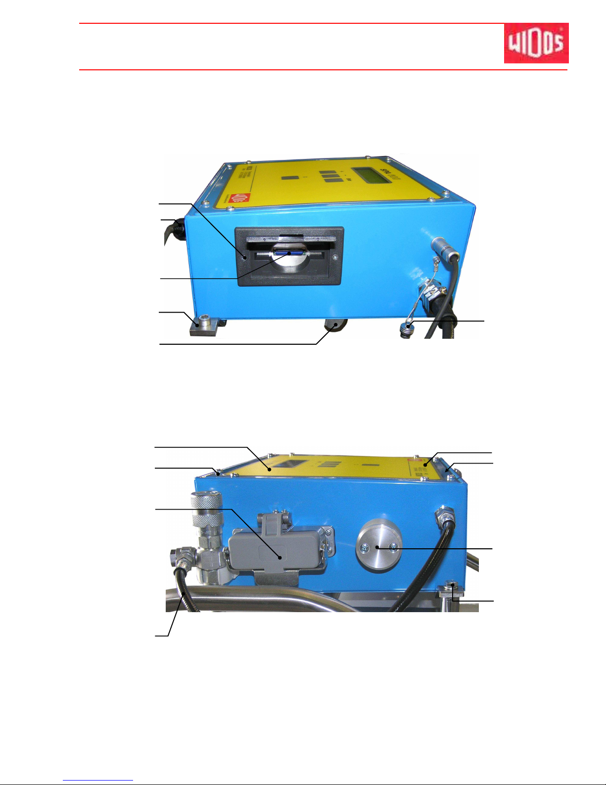
Kunststoff schweißtechnik
Spare parts list Chapter 12
16.01.12 W orking Instructions WIDOS 20000 Page 89 of 98
12.5.
SPA-600
8
9 - 10
1
5
14
13
15
2 - 3
11
6
7
12
16
4
Page 94
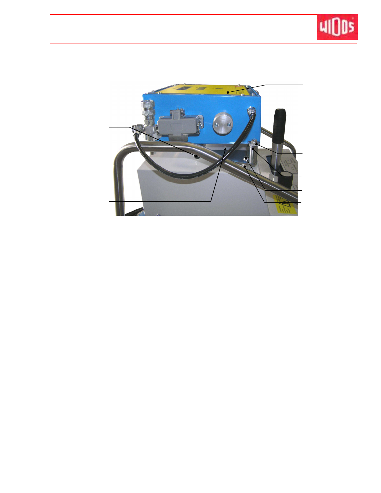
Kunststoff schweißtechnik
Spare parts list Chapter 12
16.01.2012 Betriebsanleitung WIDOS 20000 Seite 90 von 98
17
18
24 - 25
21 - 23
19
26
20
Page 95

Kunststoff schweißtechnik
Spare parts list Chapter 12
WIDOS
SPA 600
Pos. Name Piece Order no.
1 Flat-head screw M 3x16 DIN 965 2 0965C016
2 Barcode reading pencil 1 EG0603*
3 Barcode reading pencil holder 1 J9701
4 SD card 1 EPR0610
5 Mounting bracket 1 470106
6 Mounting hook 2 470107
7 Fitting cap for reading pencil holder 1 EST05471
8 Foil for front panel 1 EF0600
9 Flat-head screw M 4x10 DIN 7991 8 7991D010
10 Disc of roses M4 8 ROSM4
11 Protective cap for plug box 16-pins 1 EST0549
12 Hydraulic hose, complete 1 VS4400KP
13 Front panel 1 471102
14 Gasket for housing 1 471109
15 Outside temperature probe KTY 10 1 EE0404
16 Pan head screw M 6 x 15 DIN 912 2 0912F015
17 Support for SPA 1 106004
18 Pan head screw M 6 x 10 DIN 912 2 0912F010
19 WIDOS SPA 600 1 9701230
20 Mounting bracket for SPA 600 1 470106
21 Stud bolt 2 1060042
22 Pan-head screw M6x20 DIN 912 2 0912F020
23 Flat-heat screw M 6x15 DIN 7991 2 7991F015
24 Pan head screw M 5x40 DIN 912 2 0912E040
25 Washer M 5 DIN 9021 2 9021E
26 Distance sleeve for SPA girder 2 106005
* When ordering, please state the machine type !
16.01.2012 W orking Instructions WIDOS 20000 Page 91 of 98
Page 96
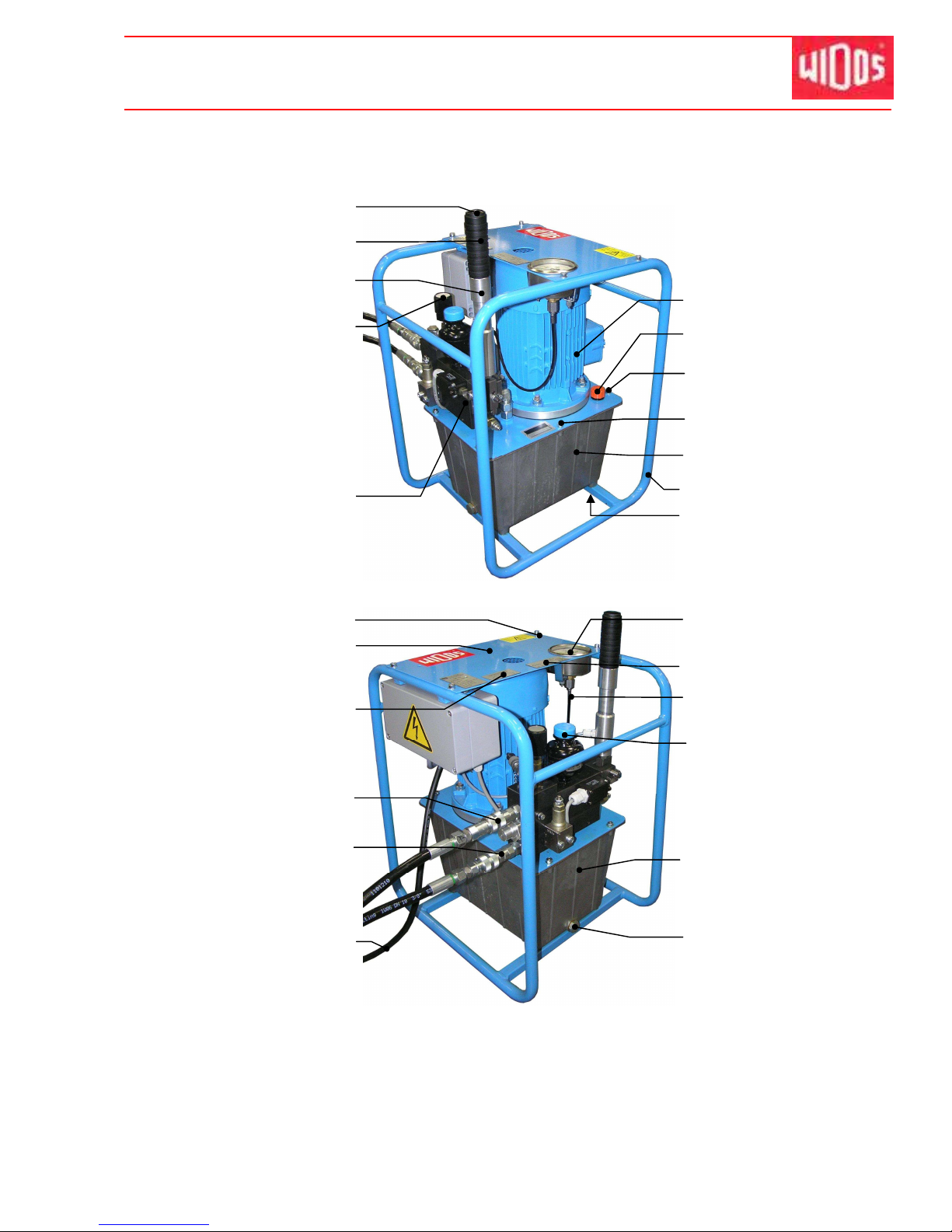
Kunststoff schweißtechnik
Spare parts list Chapter 12
16.01.12 W orking Instructions WIDOS 20000 Page 92 of 98
12.6. Hydraulic aggregate, naked (optional)
2
3 - 4
1
23 - 24
19
17 - 18
25 - 26
27
5
20
21
22
13
10 - 11
9
12
6
32
28
14
15 - 16
29 - 30
7 - 8
31
Page 97

Kunststoff schweißtechnik
Spare parts list Chapter 12
Hydraulic aggregate
WIDOS 20000
Pos. Name Piece Article No.
1 Pushbutton 1 ES3801
2 Grip with thread 1 H09061
3 Grip for hydraulic aggregate 1 101022
4 Skintop-screwing M 12 x 1,5 1 EV1012
5 Button for pressure setting 1 101022
6 Valve box 1 on request
7 Pole changing switch for motor 1 ADP1060
8 Shaft adapter for motor 1 1060117
9 Oil dipstick 1 1010212
10 Hexagon nut M 5 DIN 934 6 0934E
11 Washer M 5 DIN 125 6 0125E
12 Tank cover 1 233236
13 Oil tank 10 l 1 on request
14 Protective mounting for hydraulic aggregate 1 233221
15 Pan-head screw M 8x25 DIN 912 4 0912H025
16 Washer M8 DIN 125 4 0125H
17 Pan-head screw M 6x10 DIN 912 4 0912F010
18 Washer M 6 DIN 125 4 0125F
19 Covering for distributor valve 1 233233
20 Plate "Release pressure" 1 SCHD-L
21 Coupling sleeve, flat sealing 2 VMU14
22 Coupling plug, flat sealing 2 VST14
23 Connecting cable H07 RN-F 5x16,0mm² 1 EL025160
24 Plug 16 A, phase converter 1 EST01416
25 Pressure gauge 0-250 bar 1 023004
26 Screwed connection for pressure gauge 1 V042314
27 Plate "Pressure gauge setting value" 1 SCHM6100
28 Mini hose 1 V0400140
29 Pressure accumulator 1 104206
30 Seal ring 1 D13,7x22
31 Hydraulic pump 1 on request
32 Oil drain screw 1 on request
16.01.2012 Working Instructions WIDOS 20000 Page 93 of 98
Page 98
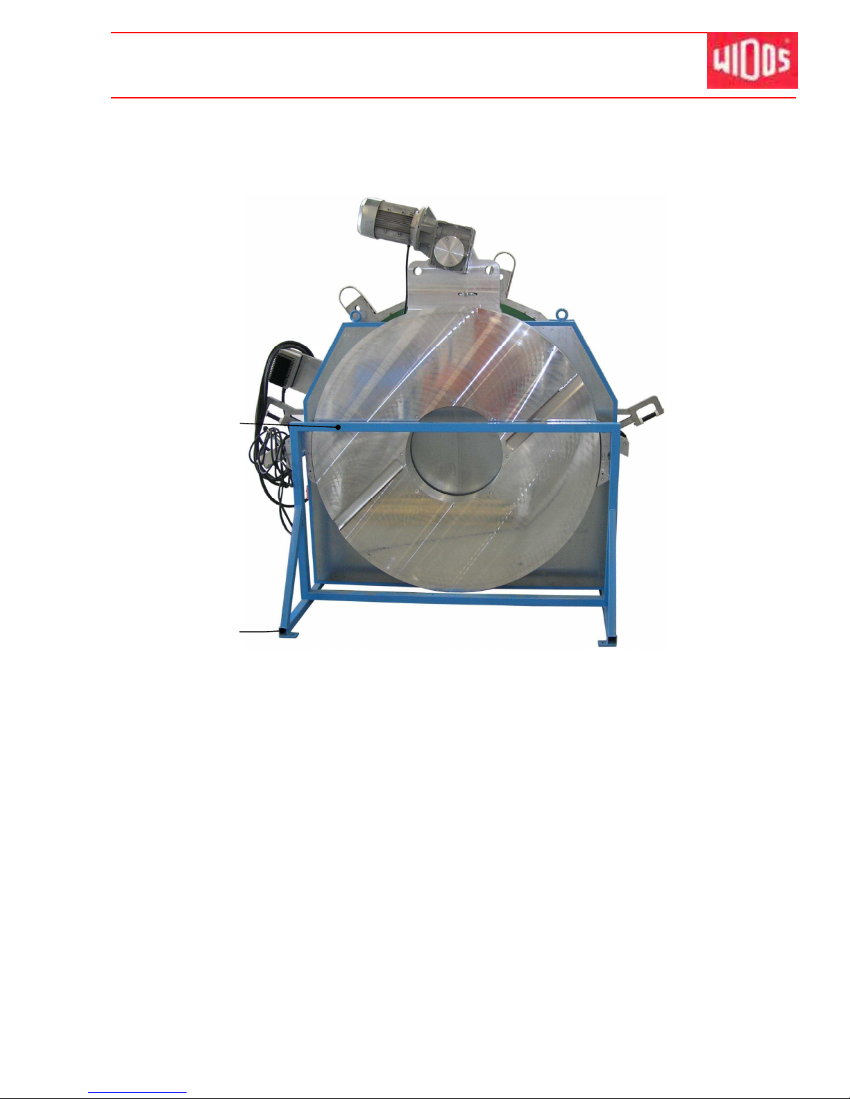
Kunststoff schweißtechnik
Spare parts list Chapter 12
16.01.12 W orking Instructions WIDOS 20000 Page 94 of 98
12.7. Protection box
2
1
Page 99

Kunststoff schweißtechnik
Spare parts list Chapter 12
Protection box
WIDOS 20000
Pos. Name Piece Article no.
1 Protection box, complete 1 2295421
2 Protective cap 60 x 60 x 3 4 J0228
16.01.2012 W orking Instructions WIDOS 20000 Page 95 of 98
Page 100
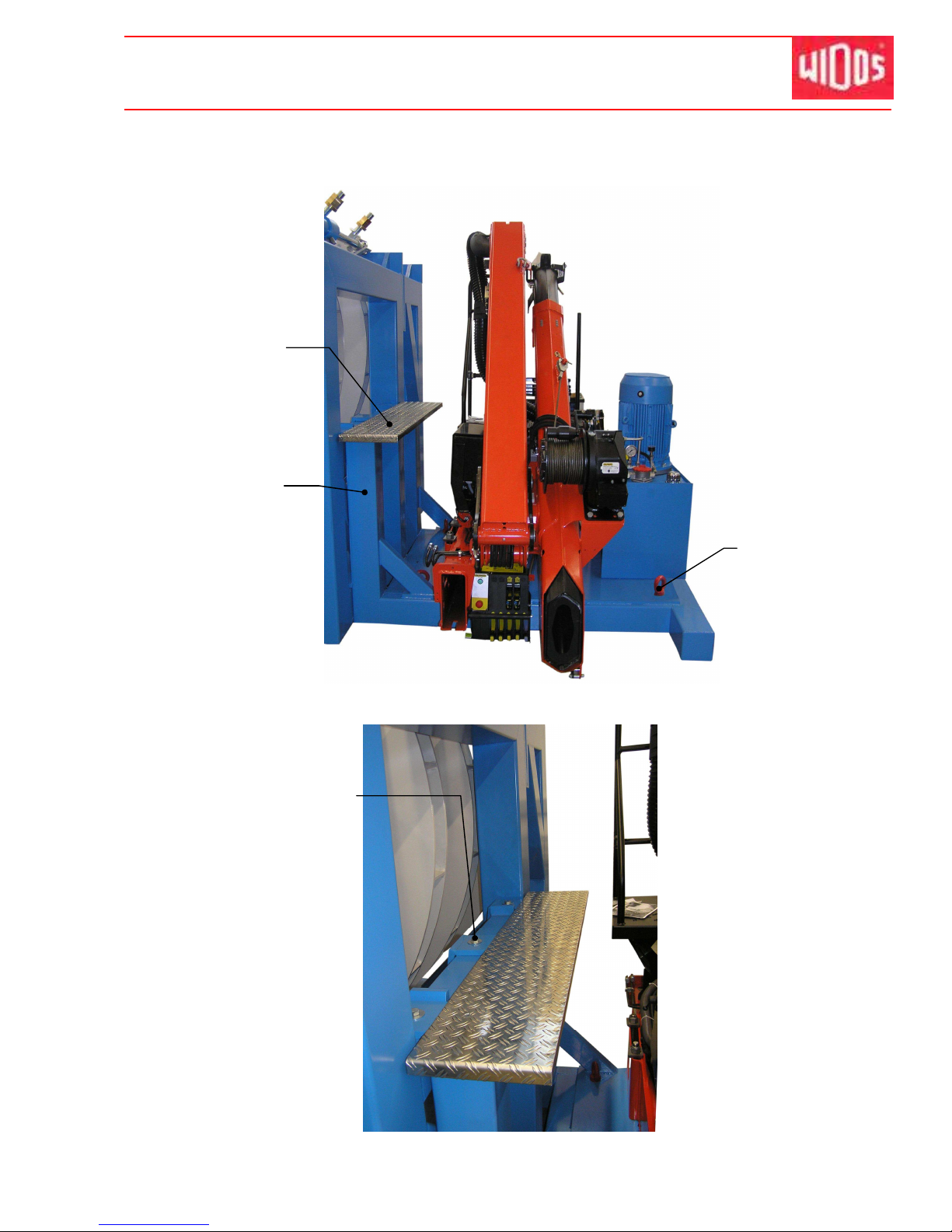
Kunststoff schweißtechnik
Spare parts list Chapter 12
16.01.12 W orking Instructions WIDOS 20000 Page 96 of 98
12.8. Assembly frame for crane (optional)
1 - 2
3
4
5 - 6
 Loading...