

EN English UME-0503-100815
L
Universal Double
Switch
WiDom
N
O1O2I2 I1
WDS 1.04 Installation and Operating Instructions
UNIVERSAL DOUBLE SWITCH

II
Revision History
Rev.
Doc.
Date
Revisor
Page
Description
1
23/09/2015
RC
All
Initial Draft
2
23/10/2015
GG
All
Minor changes
1
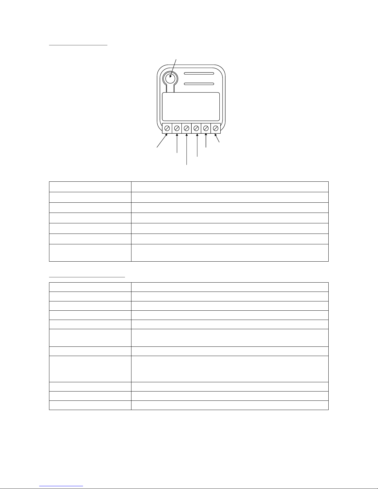
Device Description
Line
Push Button
Null
Output 1
L
Universal Double
Switch
WiDom
N
O1O2I1 I2
Output 2
Null Signal 1
Null Signal 2
Line
Phase connection terminal
Null
Neutral connection terminal
Null Signal 1
Neutral signal to activate the output 1
Null Signal 2
Neutral signal to activate the output 2
Output 1
Phase Output 1 referred to Neutral
Output 2
Phase Output 2 referred to Neutral
Push Button
Service button: 1 click to add the device to the Z-Wave network, 3 clicks to
remove it, 6 clicks to reset to factory settings
Technical Specifications
Power Supply
230 VAC±10% 50/60 Hz
Maximum Load on Relay
Resistive Loads: 8 A for each channel; 10A for both channels
Limit Temperature
105 °C
Work Temperature
-10 – 40 °C
Radio Protocol
Z-Wave 868,4 MHz
Radio Range
Up to 100 m outdoor
Up to 40 m indoor
Dimensions (WxDxH)
37x37x17 mm
Consumption
< 260 mW in standby
< 480 mW with one working load
< 700 mW with both working loads
Electrical IP Rating
IP 20
Actuator element
Relay
Conformity
CE, RoHS

2
Introduction
Universal Double Switch is an ON/OFF control device designed to independently control two separate loads,
suited for use as both a local and remote switch. Similarly to the other WiDom “in wall” devices, it can be fully
integrated into pre-existing systems and configured to associate configurable behaviours to a specific number
of clicks, in full integration with the Z-Wave home automation ecosystem.
Each of its two channels features an integrated consumption measurement device. The Universal Double
Switch also boasts the lowest energy consumption on the market.
At the same time, it is completely configurable so that it can adapt to the most varied needs while also being
ready to be used without needing additional configurations in order to operate.
Thanks to the framework developed by WiDom, the various types of “events” on the “External Switch” can be
recognised and associated to actions to be performed on the device, on any associated devices, on all devices
on the network. The events that the system recognises are the number of “clicks” or hold on the External
Switch.
External switch: External button or switch connected to the input I1 or I2
Events: The actions performed on the external Switch: Clicks or Hold.
Click: If the external switch is a button (when pressed it autonomously returns to the initial position), a
click means pressing and then releasing it. If the external switch is bistable (when pressed it does not
return to the initial position), a single click means one single flip of the switch.
1
Installation
INFO: WiDom Energy Driven Switch is designed for installation in flush mounting boxes, close to the
loads to be controlled.
WARNING: WiDom Universal Double Switch must be installed by electricians qualified to operate on
electrical systems in compliance with safety requirements set out by current regulations.
DANGER: WiDom Universal Double Switch must be connected to 230V AC voltage mains supplies;
please ensure that the general switch is in the OFF position prior to carrying out any operation.
DANGER: Any operation requiring the use of service button (B) must only be carried out during the
installation phase and must be considered as a service procedure to be performed by qualified
personnel. This operation must be carried out by adopting all necessary precautions to operate on areas with
a single level of isolation.
WARNING: Do not connect loads exceeding the maximum power load permitted by the relay contacts.
WARNING: All connections must be performed according to the electrical diagrams provided.
WARNING: WiDom Universal Double Switch must be installed in norm-compliant systems suitably
protected from overloads and short circuits.
Attivazione del WiDom Universal Double Switch
1) Ensure that the main power switch is set in the OFF position
2) Connect the device following the diagrams provided
3) Shut the electrical box containing the device
4) Turn the main power switch back on
5) Include the device into the Z-Wave network
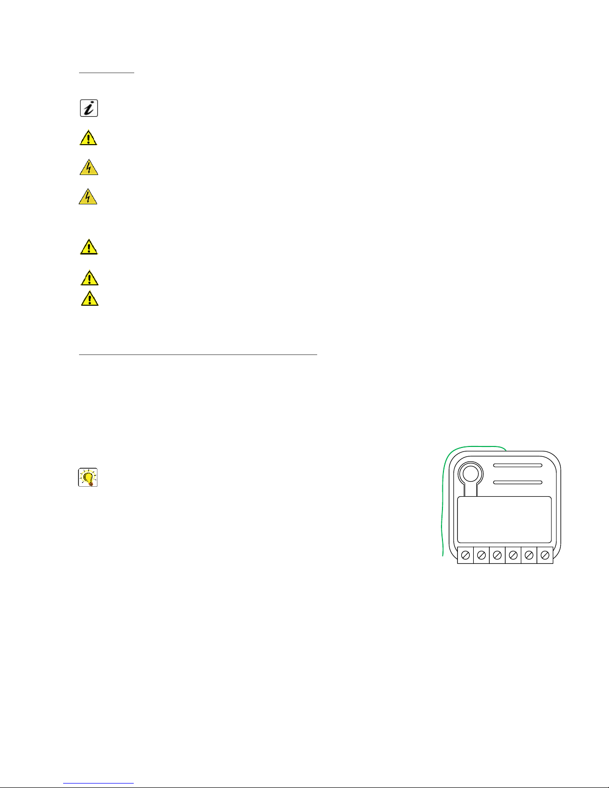
TIP: The antenna must not be shortened, removed or modified. To ensure
maximum efficiency, it must be installed as shown. Large size metal equipment
near the antenna can negatively affect reception. Each WiDom device is a node in a
mesh network. If there are metal obstacles, the obstacle can often be overcome with
a further triangulation node.
L
Universal Double
Switch
WiDom
N
O1O2I2 I1
2
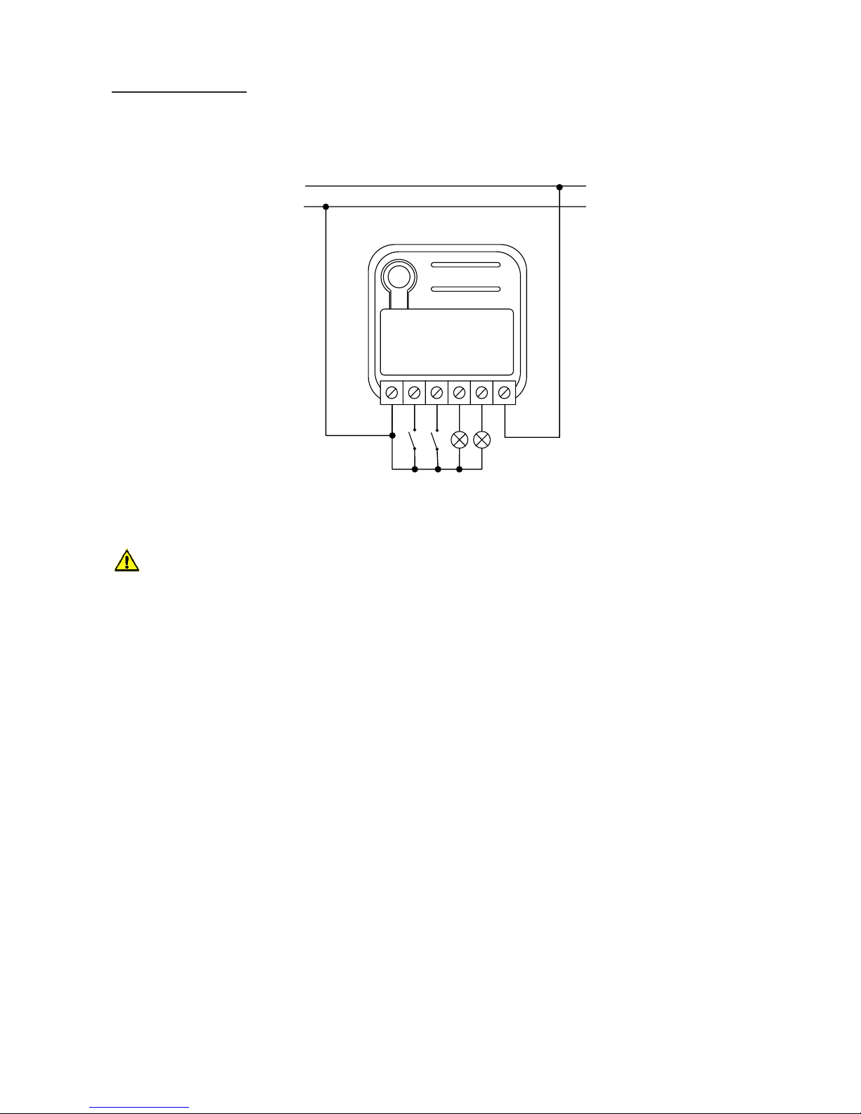
Electrical Connections
The device must be supplied by phase and neutral. Connections must be made according to one of the
diagrams below.
L
N
Main AC
L
Universa l Double
Switch
WiDom
N
O1O2I2 I1
WARNING: The line must be properly protected from overloads and short circuits related to a possible
failure of the loads connected to the output O1 and O2.

3
Reset to factory settings
The device can be reset to the original factory settings by means of one of the following methods:
Method 1: Remove the device from the Z-Wave network;
Method 2: Six consecutive clicks on (B) button or on one of the buttons/switches connected to I1 or I2 within
1 minute from system start-up;
Method 3: Set the parameter 61 to 0 – FACTORY RESET (see Configuration Parameters).
INFO: If the device is reset when included in a network, the latter will notify its removal (Device Reset
Locally Notification). Conversely, if WiDom Energy Driven Switch receives a notification of removal of
another device from the network, this device will be removed from its associations.
Including (Add) the device into an existing Z-Wave network
WiDom Universal Double Switch can be included into any Z-Wave network and operate with Z-Wave devices
from any other manufacturer. WiDom Universal Double Switch, used as a constantly powered node, will act
as a signal repeater to increase the network reliability.
The device supports both the Network Wide Inclusion (which offers the opportunity of inclusion into a network
even if the device is not directly connected to the controller) and the Normal Inclusion mechanisms.
If the device is not included into a Z-Wave network, a single click on the (B) button or on one of the external
switches will launch the process of traditional inclusion. If the device inclusion procedure does not start within
2 seconds, the Network Wide Inclusion network will be launched lasting a variable amount of time between
15-30 seconds.
INFO: Through the inclusion procedure, activated with a single click on one of the external switches, the
system determines the type of external switch (see parameter No. 62).
Excluding (Remove) the device from a Z-Wave network
Only a controller can remove a device from the network. WiDom Universal Double Switch is compatible with
all Z-Wave certified controllers. After the exclusion procedure has been activated by the controller, the device
can be removed, putting it in Exclusion Mode by three consecutive clicks on the (B) button or on the external
switch, when available.

4
Associations
WiDom Universal Double Switch is a device with two independent channels, each of which can be controlled
independently. WiDom Universal Double Switch can control other devices both of traditional and multi-channel
type.
WiDom Universal Double Switch can control other devices such as relays or dimmers. WiDom Universal
Double Switch supports 5 association groups, each of which supports the association of up to 8 devices:
Group ID
Group Name
Profile
Commands received
Description
1
LifeLine
Group
General:
LifeLine
Switch Binary Report,
Device Reset Locally
Notification, Meter
Report
Devices to receive notifications on:
status changes; instantaneous
power level; device local reset
2
On/Off control
(Switch 1)
Control:Key1
Switch Binary Set
Devices controlled by switch 1
3
Dimming
control
(Switch 1)
Control:Key1
Basic Set
Devices controlled by switch 1
4
On/Off control
(Switch 2)
Control:Key2
Switch Binary Set
Devices controlled by switch 2
5
Dimming
control
(Switch 2)
Control:Key2
Basic Set
Devices controlled by switch 2
TIP: WiDom Universal Double Switch can control up to 8 devices for every group. In order to prevent
the network from slowing down it is advisable to limit the associated devices to no more than 5 per
group.

5
Controlling the device with external switch
With WiDom devices, the normal switches/buttons found in a traditional electrical system can become
intelligent control systems.
Controlling the device through Z-Wave network
All Z-Wave controllers can control the device by using the Basic Set command.
The behaviour of the device based on its status and the commands received from the network can also be
configured.
Switch ALL ON/OFF
By default, WiDom Universal Double Switch accepts Switch All ON/OFF commands.
Timer Management
Timer management for each independent channel both switch on and switch off.
Energy management
Each of two channels has an independent meter of energy consumed.
Firmware Update
The system supports over-the-air firmware updates that do not require the device to be removed from its
location. The firmware update can be activated from all certified controllers supporting version 2 of the
Firmware Update function. The firmware update procedure must be enabled on the device with four
consecutive clicks. The activation lasts 10 seconds, after which the firmware update procedure will need to be
re-enabled if it has not been activated in the first instance.
WARNING: The system will be rebooted at the end of the firmware update procedure. If a load is
connected to the relay output, it will be disconnected and reconnected, depending on the settings
configured for system rebooting. It is advisable to carry out the firmware update procedure only when
necessary and following careful planning of the intervention.

6
Configurations
The output O1 is controlled by events on the switch connected to I1, the output O2 is controlled by events on
the switch connected to I2. The change of status of the two channels depends on the initial status and on the
number of clicks.
Parameter No. 1: Outputs status upon receipt of 1 click on its command (1 byte)
Defines the status of the output O1/O2 when the switch connected to I1/I2 receives 1 Click.
Configuration
Initial Status of
the channel
Final Status
1 – TOGGLE
(Default Value)
ON
OFF
OFF
ON
2 – ON
ON
If the initial status is OFF the system switches to ON;
conversely, it maintains its status (ON).
OFF
3 – OFF
ON
If the initial status is ON the system switches to OFF;
conversely, it maintains its status (OFF).
OFF
4 – IGNORE
ON
The device maintains the initial status
OFF
Parameter No. 2: Outputs status upon receipt of 2 clicks on its command (1 byte)
Defines the status of the output O1/O2 when the switch connected to I1/I2 receives 2 Click.
Configuration
Initial Status of
the channel
Final Status
1 – TOGGLE
(Default Value)
ON
OFF
OFF
ON
2 – ON
ON
If the initial status is OFF the system switches to ON;
conversely, it maintains its status (ON).
OFF
3 – OFF
ON
If the initial status is ON the system switches to OFF;
conversely, it maintains its status (OFF).
OFF
4 – IGNORE
ON
The device maintains the initial status
OFF
Parameter No. 3: Type of outputs (1 byte)
Defines if the outputs are controlled individually, as a traditional device with two channels, or if its behaviour
simulates a single pole double throw relay.
Configuration
Device reaction
0 – SINGLE CHANNELS
(Default Value)
Channel 1 and Channel 2 are controlled individually
From 1 to 127 – SINGLE POLE
DOUBLE THROW RELAY
The two channels are in opposite status. If the Channel 1 is close the
Channel 2 is open, if the Channel 1 is open the Channel 2 is close. The
value of the parameter defines the closing delay of the relay in tenth of
seconds

7
Controlling the associated devices
Define the events that control the associated devices.
Parameter No. 4: Number of clicks that activate the control of the associated devices (1 byte)
Defines the number of clicks on the Switch 1 or Switch 2 that enable the control of the correspondent
associated devices.
Configuration
Device reaction
1 – 1 CLICK
Associated devices are controlled by 1 Click on the correspondent
external switch
2 – 2 CLICKS
(Default Value)
Associated devices are controlled by 2 Clicks on the correspondent
external switch
TIP: Through this parameter, together the setting of the parameters 1 and 2, it is possible to control
simultaneously the local load and the associated devices (e.g. 1 click control both local load and
associated devices) or in totally independent way (e.g. 1 click control only the local load, 2 clicks control only
the associated devices).
Parameter No. 5: Level used to control the devices associated to group 2 and 3 (1 byte)
Defines how to control the devices associated to group 2 and 3.
Configuration
Action performed on the associated device
0 – SWITCH_OFF
The associated devices are switched OFF
-1 – SWITCH_ON
The associated devices are switched ON
From 1 to 99
The associated devices (dimmer, roller shutters)
are set to the indicated level (only for devices
associated to group 3)
100 – RELAY_STATUS
(Default Value)
If the Relay 1 is ON/OFF, the associated devices
are ON/OFF
101 – RELAY_STATUS_BUT_IGNORE_IF_OFF
If the Relay 1 is ON the associated devices are ON;
if it is OFF no action is taken on the associated
devices
102 – RELAY_STATUS_BUT_IGNORE_IF_ON
If the Relay 1 is OFF the associated devices are
OFF; if it is ON no action is taken on the associated
devices
103 – RELAY_OPPOSITE_BUT_IGNORE_IF_OFF
If the Relay 1 is ON the associated devices are
OFF; if it is OFF no action is taken on the
associated devices
104 – RELAY_OPPOSITE_BUT_IGNORE_IF_ON
If the Relay 1 is OFF the associated devices are
ON; if it is ON no action is taken on the associated
devices
105 – RELAY_OPPOSITE
If the Relay 1 is ON/OFF, the associated devices
are OFF/ON
106 – IGNORE
No action is taken on the associated devices

8
Parameter No. 6: Level used to control the devices associated to group 4 and 5 (1 byte)
Defines how to control the devices associated to group 4 and 5.
Configuration
Action performed on the associated device
0 – SWITCH_OFF
The associated devices are switched OFF
-1 – SWITCH_ON
The associated devices are switched ON
From 1 to 99
The associated devices (dimmer, roller shutters)
are set to the indicated level (only for devices
associated to group 5)
100 – RELAY_STATUS
(Default Value)
If the Relay 2 is ON/OFF, the associated devices
are ON/OFF
101 – RELAY_STATUS_BUT_IGNORE_IF_OFF
If the Relay 2 is ON the associated devices are ON;
if it is OFF no action is taken on the associated
devices
102 – RELAY_STATUS_BUT_IGNORE_IF_ON
If the Relay 2 is OFF the associated devices are
OFF; if it is ON no action is taken on the associated
devices
103 – RELAY_OPPOSITE_BUT_IGNORE_IF_OFF
If the Relay 2 is ON the associated devices are
OFF; if it is OFF no action is taken on the
associated devices
104 – RELAY_OPPOSITE_BUT_IGNORE_IF_ON
If the Relay 2 is OFF the associated devices are
ON; if it is ON no action is taken on the associated
devices
105 – RELAY_OPPOSITE
If the Relay 2 is ON/OFF, the associated devices
are OFF/ON
106 – IGNORE
No action is taken on the associated devices

9
Timer management
Parameter No. 10 (0xA): Timer to switch ON the Channel 1 (2 byte)
Defines the time after which the Channel 1 is switched ON.
Configuration
Device reaction
0
(Default Value)
Timer disabled
From 1 to 32000 (seconds)
After this time the relay of the Channel 1 is ON
Parameter No. 11 (0xB): Timer to switch ON the Channel 2 (2 byte)
Defines the time after which the Channel 2 is switched ON.
Configuration
Device reaction
0
(Default Value)
Timer disabled
From 1 to 32000 (seconds)
After this time the relay of the Channel 2 is ON
Parameter No. 12 (0xC): Timer to switch OFF the Channel 1 (2 byte)
Defines the time after which the Channel 1 is switched OFF.
Configuration
Device reaction
0
(Default Value)
Timer disabled
From 1 to 32000 (seconds)
After this time the relay of the Channel 1 is OFF
Parameter No. 13 (0xD): Timer to switch OFF the Channel 2 (2 byte)
Defines the time after which the Channel 2 is switched OFF.
Configuration
Device reaction
0
(Default Value)
Timer disabled
From 1 to 32000 (seconds)
After this time the relay of the Channel 2 is OFF

10
Controlling the device through Z-Wave network
Parameter No. 20 (0x14): Outputs status upon receipt of a Multi-Channel Basic Set command (1 byte)
The two channels can be controlled individually by Z-Wave network. The status of the channels upon receipt
of a Multi-Channel Basic Set command is defined by the value set on the parameter.
Configuration
Command received
Final Status
1 – AS RECEIVED
(Default Value)
ON
ON
OFF
OFF
2 – IGNORE IF ON
ON
Maintains the initial status
OFF
OFF
3 – IGNORE IF OFF
ON
ON
OFF
Maintains the initial status
4 – IGNORE
ON
Maintains the initial status
OFF
Parameter No. 21 (0x15): Outputs status upon receipt of a Basic Set command (1 byte)
The channels of the device can be controlled individually from all other Z-Wave devices that support the
multichannel feature. In order to support also the integration with no-multichannel systems, this parameter
allows to define if the receipt of a no-multichannel command controls only the Channel 1 or both.
Configuration
Device reaction
1 – CHANNEL 1
The receipt of a Basic Set ON/OFF set the Channel 1 to ON/OFF
3 – BOTH CHANNELS
(Default Value)
The receipt of a Basic Set ON/OFF set both the Channel 1 and the
Channel 2 to ON/OFF

11
Other configuration parameters
Parameter No. 60 (0x3C): Start-up status (1 byte)
Defines the status of the device following a restart.
Configuration
Device reaction
0 – OFF_OFF
Both Relay 1 and Relay 2 OFF
1 – ON_OFF
Relay 1 ON, Relay 2 OFF
2 – OFF_ON
Relay 1 OFF, Relay 2 ON
3 – ON_ON
Both Relay 1 and Relay 2 ON
4 – PREVIOUS STATUS
(Default value)
Status prior to restart
Parameter No. 61 (0x3D): Configuration reset (1 byte)
Defines which parameters should be reset to default values.
Configuration
Device reaction
0 – FACTORY RESET
The device is reset to the original factory settings
1 – ASSOCIATIONS RESET
All associations and only the associations are reset
2 – CONFIGURATIONS RESET
The associations are maintained while all other configuration parameters
are reset to the original factory settings, except for the specific configuration.
3 – RESTART DEVICE
The device will be restarted
4 – IGNORE
(Default value)
No action is performed
Parameter No. 62 (0x3E): Type of external switch (1 byte)
Defines the type of external switch connected to the device.
Configuration
Device reaction
0 – IGNORA
The actions on the external switch are ignored. In this mode, the device
can only be controlled via the network.
1 – BUTTON
The external switch is a normally open button
2 – SWITCH
The external switch is a traditional switch
4 – AUTOMATIC RECOGNITION
(Default value)
After the first single click on the external switch, the system automatically
determines the type of external switch used and sets the parameter with
the new value accordingly.

12
Disposing the devices
This product bears the selective sorting symbol for waste electrical and electronic equipment
(WEEE).
This means that this product must be handled pursuant to European Directive 2002/96/EC in
order to be recycled or dismantled to minimize its impact on the environment.
For further information, please contact your local or regional authorities.
Electronic products not included in the selective sorting process are potentially dangerous for
the environment and human health due to the presence of hazardous substances.
Compliance with directives
WiDom devices are built in compliance with directives LVD 2006/95/EC, EMC 2004/108/CE and R&TTE
Widom shall not be held responsible for any damage caused by these devices if they are used in a manner
that is not compliant with the instructions in this manual. WiDom reserves the right to make any changes to
the product that it considers necessary or useful without jeopardising its primary features.
Warranty
This warranty is provided by WiDom srl (hereinafter “WiDom”) based in Quartu S.Elena 09045 (CA), Italy (VAT number
03452490927).
WiDom warrants to the original purchaser (hereinafter “Customer”) that the device sold under this agreement (hereinafter
“Device”) is free from defects in parts and workmanship under normal use for 12 months from date of purchase (“Warranty
Period”).
The original purchase invoice or sales receipt, showing the date of purchase is the proof of date of purchase by the Customer.
If a Device, sold by WiDom to the Customer, has manufacturing defects or in any case of alleged lack of conformity, the
Customer shall send within thirty (30) days from the day in which he discovers such defects, a claim form by using the web
site (www.widom.it) informing WiDom on the full name of the Customer, the nature of the defects and the date in which the
Devices has been purchased.
Warranty Claims received after the expiration of the Warranty Period shall not be considered valid.
Once WiDom, receives the Warranty Claim, it shall inform the Customer by e-mail or letter, if the Warranty is applicable and
the address where the Device shall be sent in order to verify the defects (if any). Customer must prepay shipping and
transportation charges as indicated by WiDom. The Device shall be sent by the Customer to WiDom at its own costs and
expenses, by express courier or hand delivered, and with the original packaging, the supplied accessories (if any) and
documents proving date of purchase. WiDom shall then inform the Customer about the defects and on its repair or replacement
(where applicable). Should WiDom not evidence defects on the Device, the Device shall be returned to the Customer.
Should WiDom notices the defects, and this warranty is applicable, it will remove, at its sole discretion, any defect, free of
charge, by repairing any defective components of the Device with new or regenerated components or by replacing the Device.
The Warranty Period of the replaced or repaired Device shall not be extended.
WiDom will ship the repaired or a replaced Device to Customer freight prepaid.
WiDom will not be liable for damages to property caused by faulty device. WiDom will not be liable for indirect, incidental,
special, consequential or punitive damages, or for any damage, including, inter alia, loss of profits, savings, data, loss of
benefits, claims by third parties and any property damage or personal injuries arising from or related to the use of the Device.
If the Device cannot be replaced with another of the same type (e.g. the Device is no longer in production or no longer available
for selling in the Customer’s country), it may be replaced with a different one having similar technical specifications to the
faulty one. Such replacement shall be considered as a total fulfilment of WiDom’s obligations.
Warranty exclusion
- defects caused by normal wear of parts or especially subject to wear, such as parts that require periodic replacement during
the normal operation of the system (e.g. Batteries);

13
- splits, cracks, scratches, dents, scratched or discolored surfaces and parts, breakage of plastic parts and in general of any
other cosmetic damage;
- damages resulting from use of the system other than that provided, including but not limited to the failure to follow
instructions contained in the operating manual;
- damages caused by accident, abuse, misuse, dirt, viruses, liquid contact, fire, earthquake, improper or inadequate
maintenance or calibration, negligence or other external causes;
- environmental damage and / or defects caused by smoke, dust, dirt, soot, or other external influences;
- damages caused by modifications and alterations in the functionality or features without the written permission of WiDom;
- damages resulting from transportation or inadequate packaging when returning the product to a WiDom or to an authorize
service center;
- defects caused by force majeure events such as lightning, floods, fires, incorrect voltage, improper ventilation;
- damages caused by malfunctioning software, computer virus attack, or by failure to update the software as recommended
by WiDom;
- damages resulting from surges in the power and/or telecommunication network, improper connection to the grid in a manner
inconsistent with the operating manual, or from connecting other devices not recommended by WiDom;
- damages caused by operating or storing the device in extremely adverse conditions, i.e. high humidity, dust, too low (freezing)
or too high ambient temperature;
- products whose serial number has been removed, damaged or rendered illegible;
- expiration of the Warranty Period.
If a defect is not covered by the Warranty, WiDom will inform the Customer about the extra expenses for the repair or
replacement.
This warranty may be subject to changes. Please check at www.widom.it the newest warranty claim procedure.
This guarantee shall not exclude, limit or suspend the Customer rights when the provided product is inconsistent with the
purchase agreement.
© All rights reserved. WiDom is a trademark of WiDom srl. All other brand names, product names, or trademarks belong to
their respective owners. WiDom reserves the right to change product features and specifications at any time without notice,
and is not responsible for typographical or graphical errors that may appear in this document.
Please check at www.widom.it the newest version of this document.
Printed in Italy on low-impact recyclable paper.
 Loading...