

EN English UME-1000-300418
LN
Smart Dry Contact
WiDom
Ls
1 2
N
Smart Dry Contact Switch
Smart Dry Contact Switch Operating instructions

Rev. Doc.
Date
Reviser
Page
Description
0
15/01/2019
GT Initial version
Revision History
Content
Revision History ................................................................................................................................................. II
Device description ............................................................................................................................................. 1
Technical Specification ...................................................................................................................................... 2
Safety information .............................................................................................................................................. 2
Electrical Connections diagram ......................................................................................................................... 3
Device Installation .............................................................................................................................................. 3
LED status indicator ........................................................................................................................................... 4
Including the device into an existing Z-Wave network ...................................................................................... 4
Excluding the device from a Z-Wave network ................................................................................................... 5
Reset to the factory settings .............................................................................................................................. 5
Firmware Update ............................................................................................................................................... 6
Controlling the device ........................................................................................................................................ 6
Controlling the Smart Dry Contact Switch by External Switches................................................................... 6
Controlling the Smart Dry Contact Switch by the controller .......................................................................... 6
Associations ....................................................................................................................................................... 7
Configurations .................................................................................................................................................... 8
Controlling the associated devices ................................................................................................................ 8
Timer management ........................................................................................................................................ 9
Disposing the devices ...................................................................................................................................... 11
Compliance with directives .............................................................................................................................. 11
Warranty .......................................................................................................................................................... 11
Warranty exclusion ...................................................................................................................................... 12
Extended warranty activation .......................................................................................................................... 12
Smart Dry Contact Switch - Operating Instructions II
LN
Smart Dry Contact
WiDom
Ls
1 2
N
Line
Line Signal
Dry
Contact
Null
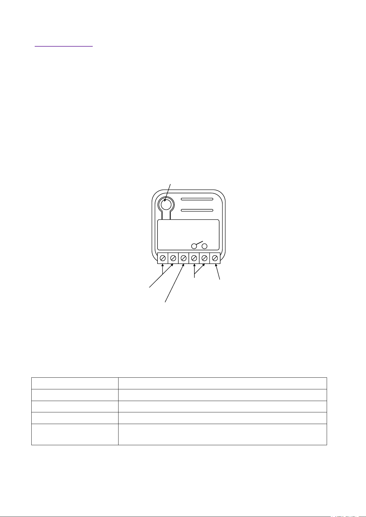
Integrated Button
Line
Phase connection terminal
Null
Neutral connection terminal
Dry Contact
16A contact relay
Line Signal
External Switch Connection
Integrated Button
1 click to enter in Learn Mode
6 clicks to reset the system to manufacturer's settings
Device description
WiDom Smart Dry Contact Switch can turn ON and OFF equipments with an independent power supply,
such as solenoid valves (e.g. gas, water and irrigation), power operated valves etc.
WiDom Smart Dry Contact Switch is very easy to install and works with both momentary and toggle
switches.
The device is equipped with contact protection technology (Zero Crossing) which reduces the electrical
stress on the relay contacts and ensures a longer life. The open / closed switching of the device always
occur when the instantaneous value of voltage is 0.
It operates in any Z-Wave network with other Z-Wave/Z-Wave Plus certified devices and controllers from
any other manufacturer. As a constantly powered node, WiDom Smart Double Switch will act as repeater
regardless of the vendor in order to increase the reliability of the network.
Smart Dry Contact Switch - Operating Instructions 1
Power supply
110 - 230 VAC±10% 50/60 Hz
Maximum Load on Relay
13A resistive Load
System temperature limitation
105°C
Work temperature
From -10° to 40° C
Power consumption
< 260 mW in standby
< 480 mW with working load
Radio frequency
Check the radio frequency section
Protection system
S0 and S2 Security
Maximum distance
Up to 100 m outdoor
Up to 40 m indoor
Dimensions
37x37x17 mm
Actuator element
16 Amp relay
Compliance
CE, RoHs
Electrical IP Rating
IP20
Product Code
Z-Wave Frequency
Product Code
Z-Wave Frequency
DRYEU
868.4MHz,
DRYAU
919.8MHz,
DRYBR
919.8MHz, 921.4MHz
DRYCN
868.4MHz
DRYCL
919.8MHz, 921.4MHz
DRYHK
919.8MHz
DRYCO
908.4MHz, 916MHz
DRYIL
916MHz
DRYIN
865.2MHz
DRYMY
919.8MHz, 921.4MHz
DRYJP
922.5MHz, 923.9MHz, 926.3MHz
DRYSG
920.9MHz, 921.7MHz, 923.1MHz
DRYRU
869.0MHz
DRYKR
920.9MHz, 921.7MHz, 923.1MHz
DRYZA
868.4MHz, 869.85MHz
DRYTH
920.9 MHz, 921.7MHz, 923.1 MHz
DRYTW
922.5MHz, 923.9MHz, 926.3MHz
DRYUS
908.4MHz
DRYAE
868.4MHz, 869.85MHz
Technical Specification
Radio Frequency
Safety information
INFO: WiDom Smart Dry Contact Switch is designed to be installed in flush mounting junction boxes or
close to the load to be controlled.
WARNING: WiDom Smart Dry Contact Switch must be installed by electricians qualified to intervene
on electrical systems in compliance with safety requirements set out by the regulations in force.
DANGER: WiDom Smart Dry Contact Switch must be connected with a voltage of 230 VAC, before
carrying out any operation, please make sure the power main switch is in OFF position.
DANGER: Any procedure requiring the use of the Integrated Button is related only to the installation
phase and is to be considered a service procedure that must be performed by qualified personnel.
This operation must be performed with all necessary precautions for operating in areas with a single level of
insulation.
WARNING: Do not connect loads that exceed the maximum load permitted by the actuator element.
WARNING: All connections must be performed according to the electrical diagrams provided
WARNING: WiDom Smart Dry Contact Switch must be installed in norm-compliant systems suitably
protected from overloads and short circuits.
Smart Dry Contact Switch - Operating Instructions 2
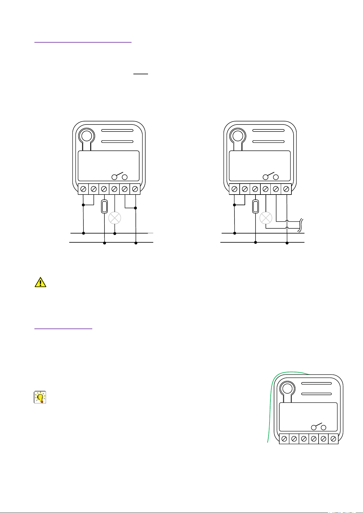
Diagram for controlling a Load in the same power supply system
Diagram for controlling a Load connected to an independent
power supply system
LN
Smart Dry Contact
WiDom
Ls
1 2
N
L
N
LN
Smart Dry Contact
WiDom
Ls
1 2
N
L
N
LN
Smart Dry Contact
WiDom
Ls
1 2
N
Electrical Connections diagram
The device must be supplied by phase and neutral.
Connections must be done following one of the diagrams below: if you need to control a Load connected on
a different power supply system you must follow the diagram on the right side.
Device Installation
1) Make sure the main switch is set to the OFF position
2) Connect the device based on the diagrams provided
3) Turn the main switch to the ON position
4) Include the device in the Z-Wave network
near the antenna can negatively affect reception. Each WiDom device is a node in a
mesh network. If there are metal obstacles, the obstacle can often be overcome with
a further triangulation node.
N) Neutral; L) Phase; Ls) External Switch; 1, 2) Dry contact
WARNING: The power line must be opportunely protected from short-circuits and excess load due to a
failure of the load.
TIP: The antenna must not be shortened, removed or modified. To ensure
maximum efficiency, it must be installed as shown. Large size metal equipment
Smart Dry Contact Switch - Operating Instructions 3

LED status indicator
The system includes an RGB LED that shows the device’s status during installation:
Solid RED: the device is not included in any network
OFF: the device is already associated to a Z-Wave network
Blink GREEN: the device has sent an unsolicited Multilevel Frame to Lifeline group
Blink YELLOW: the device has sent an unsolicited Meter Frame to Lifeline group
Blink VIOLET: the device has sent a command to the association device. The number of blinks is equal to
the ID Association group
Sequence of GREEN-BLUE Learn Mode for inclusion
Sequence of RED-BLUE Learn Mode for exclusion
INFO: The Learn Mode status is activated or deactivated by a single click on the integrated button.
TIP: To test if the electrical connections are correct, before the inclusion of the device, while pressing n
times the external switch, the RGB LED should flash green for the same amount of times. If it does
not, check the wire connections.
Including the device into an existing Z-Wave network
WiDom Smart Dry Contact Switch is compatible with all Z-Wave/Z-Wave Plus certified controllers. The
device supports both the Network Wide Inclusion mechanism (which offers the ability to be included in a
network, even if the device is not directly connected to the controller) and Normal Inclusion.
By default, the inclusion procedure starts in Normal Inclusion mode and after a short time out the procedure
continues in Network Wide Inclusion mode that lasts for about 20 Seconds.
If you are using the WiDom Multi Sensor Room Controller you can include the device in the preferred room
by clicking on the button and opening the inclusion interface.
Before including the device the LED status indicator is solid RED. The procedure of inclusion is activated by
clicking Add in the inclusion interface and by pressing any sequence of click on the integrated button. As
soon as the inclusion procedure initiates the LED indicator starts a sequence of GREEN-BLUE blinks. The
device is included in the network when the LED status is OFF and the interview is completed.
Smart Dry Contact Switch - Operating Instructions 4

Excluding the device from a Z-Wave network
Only a controller can remove the device from the network. After activating the exclusion function by the
controller, the device can be removed by setting it in Learning Mode.
If you are using the WiDom Multi Sensor Room Controller, the procedure of exclusion can be activated by
Removing a node from the Z-Wave network and any click sequence on the integrated button; as soon as
the exclusion initiates, the LED indicator starts a sequence of RED-BLUE blinks. The device is excluded from
the network when the LED status indicator is solid RED and the App_status in the interface is OK.
Reset to the factory settings
The device can be reset to the original factory settings using one of the following methods:
Method 1: Remove the device from the Z-Wave network
Method 2: 6 consecutive clicks on the integrated button
INFO: If the reset is performed while the device is still part of a network, it notifies the other devices
that it has been removed (Device Reset Locally Notification).
Smart Dry Contact Switch - Operating Instructions 5

Firmware Update
The system supports over-the-air firmware updates that do not require the device to be removed from its
location. The firmware update can be activated from all certified controllers supporting version 2 of the
Firmware Update function.
WARNING: The system will be rebooted at the end of the firmware update procedure. It is advisable to
carry out the firmware update procedure only when necessary and following careful planning of the
intervention.
Controlling the device
The WiDom Smart Dry Contact Switch can turn ON and OFF by using an external switch, or from remote
through a controller
Controlling the Smart Dry Contact Switch by External Switches
WiDom framework recognizes the number of clicks or hold event on the external switch and can be
configured to perform different actions based on the identified event.
External switch: External button or switch connected to the Line Signal terminal.
Click: If the external switch is a button (when pressed it autonomously returns to the initial position), a
click means pressing and then releasing it. If the external switch is bistable (when pressed it does not
return to the initial position), a single click means one single flip of the switch.
Hold: Applies only when the external switch is a normally opened button and occurs when the
pressure on the button lasts longer than a click.
Control Actions – Result Event
Holding the external switch changes the status of dry contact and return to the previous status as
soon as the button is released.
A single click on the external switch turns ON/OFF the load.
Controlling the Smart Dry Contact Switch by the controller
The WiDom Smart Dry Contact Switch can be controlled by any Z-Wave / Z-Wave Plus certified controller
available in the market.
In the figure below, is represented how the device will appear once included into the WiDom Multi Sensor
Room Controller.
View of the WiDom Smart Dry Contact Switch control panels inside the WiDom Multi Sensor Room Controller interface
Smart Dry Contact Switch - Operating Instructions 6

The control panel show the load status. The ON/OFF buttons in the control panel allow to turn ON/OFF the
load connected to the dry contact.
The device status is typically updated in case of status change. Nevertheless, it is possible to refresh the
shown status by using the Refresh Button .
The device configuration parameters and settings can be accessed by using the Configuration Button .
Associations
WiDom Smart Dry Contact Switch can control other devices like other relays or dimmers. WiDom Dry
Contact supports 4 association groups:
INFO: Association ensures direct transfer of control commands between devices, and is performed
without participation of the main controller.
TIP: WiDom Smart Dry Contact Switch can control up to 8 devices for each group. To avoid network
delays, we recommend limiting the amount of associated devices to no more than 5 per group.
INFO: If you want to add the device within the first group and you are using the WiDom Multi Sensor
Controller, the device association group can be configured as follows: 1) Click Configuration button,
2) select Association section, 3) click the button to Add a new device to the group or click on the
button to Remove a device.
Smart Dry Contact Switch - Operating Instructions 7

Configuration
Result
0
DISABLED
Local Control disabled
1
ONE_CLICK
1 click controls the local load
2
TWO_CLICKS
2 clicks control the local load
4
THREE_CLICKS
3 clicks control the local load
7 (Default Value)
ONE_CLICK, TWO_CLICKS or THREE_CLICKS
The load connected to the Channel 1 can be controlled using 1 click, 2 clicks
or 3 clicks
The value for the configuration parameter can be the sum of single values as below:
To control the load with 1 click and 2 clicks -> Parameter value must be 1 + 2 =3
To control the load with 1 click and 3 clicks -> Parameter value must be 1 + 4 =5
To control the load with 2 clicks and 3 clicks -> Parameter value must be 2 + 4 =6
Configuration
Result
1-99
Dimming purpose
0
OFF
-1
ON
100
The same value of dry contact status
Configuration
Result
1-99
Dimming purpose
0
OFF
-1
ON
100 (Default Value)
The same value of dry contact status
Configuration
Result
1-99
Dimming purpose
0
OFF
-1
ON
100 (Default Value)
The same value of dry contact status
Configurations
Parameter No. 1: Numbers of clicks on the external switch to control the load (1 Byte)
Defines which sequences of clicks control the load.
Controlling the associated devices
Defines the actions to be carried out on the associated devices in terms of Basic Set.
The values in the table above can be used to configure the parameters No. 4, 5, 6, 7, 8, and 9.
Parameter No. 4: Value used for devices belonging to Group 2 when the external switch receives 1
Click (1 byte).
Parameter No. 5: Value used for devices belonging to Group 3 when the external switch receives 2
Clicks (1 byte).
Smart Dry Contact Switch - Operating Instructions 8

Configuration
Result
1-99
Dimming purpose
0
OFF
-1
ON
100 (Default Value)
The same value of dry contact status
Configuration
Result
0 (Default Value)
Timer disabled
1 - 32000
Number of time units (see parameter No.15) after which the dry
contact is switched OFF
Configuration
Result
0 (Default Value)
Timer disabled
1 - 32000
Number of time units (see parameter No.15) after which the dry
contact is switched ON
Configuration
Result
1 (Default Value)
Tenth of seconds
2
Seconds
Configuration
Result
0 (Default Value)
No value is sent
1 - 255
Value sent to the Lifeline group
Configuration
Result
0 (Default Value)
No value is sent
1 - 255
Value sent to the Lifeline group
Parameter No. 6: Value used for devices belonging to Group 4 when external switch receives 3 Clicks
(1 byte).
Timer management
Parameter No. 10: Timer to switch OFF the Relay (2 byte)
Defines the time after which the relay is switched OFF.
Parameter No. 11: Timer to switch ON the Relay (2 byte)
Defines the time after which the relay is switched ON.
Parameter No. 15: Timer scale (2 byte)
Defines the time unit used for parameters No.10 and No.11.
Parameter No. 20: One Click Scene Activation Set (2 byte)
Defines the Scene Activation Set value sent to the Lifeline group with 1 Click on the external switch.
Parameter No. 21: Two Clicks Scene Activation Set (2 byte)
Defines the Scene Activation Set value sent to the Lifeline group with 2 Clicks on the external switch.
Smart Dry Contact Switch - Operating Instructions 9

Configuration
Result
0 (Default Value)
No value is sent
1 - 255
Value sent to the Lifeline group
Configuration
Result
1
ON
Relay ON
2
OFF
Relay OFF
3 (Default value)
PREVIOUS STATUS
Status prior to restart
Configuration
Result
0
IGNORE
The actions on the external switch are ignored. In this mode, the device
can only be controlled through the network.
1 (Default value)
BUTTON
The external switch is a momentary switch type
2
SWITCH
The external switch is a traditional switch (toggle switch)
Parameter No. 22: Three Clicks Scene Activation Set (2 byte)
Defines the Scene Activation Set value sent to the Lifeline group with 3 Clicks on the external switch.
Parameter No. 60: Start-up Status (1 Byte).
Defines the status of the device following a restart.
Parameter No. 62: Type of external switch (1 byte)
Defines the type of external switch connected to the device.
Smart Dry Contact Switch - Operating Instructions 10

Disposing the devices
This product bears the selective sorting symbol for waste electrical and electronic
equipment (WEEE).
This means that this product must be handled pursuant to European Directive 2002/96/EC
in order to be recycled or dismantled to minimize its impact on the environment.
For further information, please contact your local or regional authorities.
Electronic products not included in the selective sorting process are potentially dangerous
for the environment and human health due to the presence of hazardous substances.
Compliance with directives
WiDom devices are built in compliance with directives LVD 2006/95/EC, EMC 2004/108/CE and R&TTE
WiDom shall not be held responsible for any damage caused by these devices if they are used in a manner
that is not compliant with the instructions in this manual. WiDom reserves the right to make any changes to
the product that it considers necessary or useful without jeopardizing its primary features.
Warranty
This warranty is provided by WiDom srl (hereinafter “WiDom”) based in Quartu S.Elena 09045 (CA), Italy (VAT number
03452490927).
WiDom warrants to the original purchaser (hereinafter “Customer”) that the device sold under this agreement (hereinafter “Device”)
is free from defects in parts and workmanship under normal use for 12 months from date of purchase (“Warranty Period”).
The original purchase invoice or sales receipt, showing the date of purchase is the proof of date of purchase by the Customer.
If a Device, sold by WiDom to the Customer, has manufacturing defects or in any case of alleged lack of conformity, the Customer
shall send within thirty (30) days from the day in which he discovers such defects, a claim form by using the web site (www.widom.it)
informing WiDom on the full name of the Customer, the nature of the defects and the date in which the Devices has been purchased.
Warranty Claims received after the expiration of the Warranty Period shall not be considered valid.
Once WiDom, receives the Warranty Claim, it shall inform the Customer by e-mail or letter, if the Warranty is applicable and the
address where the Device shall be sent in order to verify the defects (if any). Customer must prepay shipping and transportation
charges as indicated by WiDom. The Device shall be sent by the Customer to WiDom at its own costs and expenses, by express
courier or hand delivered, and with the original packaging, the supplied accessories (if any) and documents proving date of
purchase. WiDom shall then inform the Customer about the defects and on its repair or replacement (where applicable). Should
WiDom not evidence defects on the Device, the Device shall be returned to the Customer.
Should WiDom notices the defects, and this warranty is applicable, it will remove, at its sole discretion, any defect, free of charge, by
repairing any defective components of the Device with new or regenerated components or by replacing the Device. The Warranty
Period of the replaced or repaired Device shall not be extended.
WiDom will ship the repaired or a replaced Device to Customer freight prepaid.
WiDom will not be liable for damages to property caused by faulty device. WiDom will not be liable for indirect, incidental, special,
consequential or punitive damages, or for any damage, including, inter alia, loss of profits, savings, data, loss of benefits, claims by
third parties and any property damage or personal injuries arising from or related to the use of the Device.
If the Device cannot be replaced with another of the same type (e.g. the Device is no longer in production or no longer available for
selling in the Customer’s country), it may be replaced with a different one having similar technical specifications to the faulty one.
Such replacement shall be considered as a total fulfilment of WiDom’s obligations.
Smart Dry Contact Switch - Operating Instructions 11

Warranty exclusion
- defects caused by normal wear of parts or especially subject to wear, such as parts that require periodic replacement during the
normal operation of the system (e.g. Batteries);
- splits, cracks, scratches, dents, scratched or discolored surfaces and parts, breakage of plastic parts and in general of any other
cosmetic damage;
- damages resulting from use of the system other than that provided, including but not limited to the failure to follow instructions
contained in the operating manual;
- damages caused by accident, abuse, misuse, dirt, viruses, liquid contact, fire, earthquake, improper or inadequate maintenance or
calibration, negligence or other external causes;
- environmental damage and / or defects caused by smoke, dust, dirt, soot, or other external influences;
- damages caused by modifications and alterations in the functionality or features without the written permission of WiDom;
- damages resulting from transportation or inadequate packaging when returning the product to a WiDom or to an authorize service
center;
- defects caused by force majeure events such as lightning, floods, fires, incorrect voltage, improper ventilation;
- damages caused by malfunctioning software, computer virus attack, or by failure to update the software as recommended by
WiDom;
- damages resulting from surges in the power and/or telecommunication network, improper connection to the grid in a manner
inconsistent with the operating manual, or from connecting other devices not recommended by WiDom;
- damages caused by operating or storing the device in extremely adverse conditions, i.e. high humidity, dust, too low (freezing) or
too high ambient temperature;
- products whose serial number has been removed, damaged or rendered illegible;
- expiration of the Warranty Period.
If a defect is not covered by the Warranty, WiDom will inform the Customer about the extra expenses for the repair or replacement.
This warranty may be subject to changes. Please check at www.widom.it the newest warranty claim procedure.
This guarantee shall not exclude, limit or suspend the Customer rights when the provided product is inconsistent with the purchase
agreement.
Extended warranty activation
The devices bought in the EU, entitle the end customers to a two-year guarantee offered by the retailer (or trader) that is separate
from the above commercial guarantee offered by the manufacturer to the distributor or reseller.
WiDom offers an extra year guarantee to the end customers in addition to the EU guarantee. This warranty can be obtained only if the
customer completes, by using the contacts on WiDom’s website, the following two steps:
1) Within fifteen (15) days from the date of purchase, send to WiDom a copy of the purchase invoice and product code;
2) Promptly after installing the device, send to WiDom the conformity certification issued by the professional who installed the device
with indication of the serial number.
© All rights reserved. WiDom is a trademark of WiDom srl. All other brand names, product names, or trademarks belong to their
respective owners. WiDom reserves the right to change product features and specifications at any time without notice, and is not
responsible for typographical or graphical errors that may appear in this document.
Please check at www.widom.it the newest version of this document.
Printed in Italy on low-impact recyclable paper.
Smart Dry Contact Switch - Operating Instructions 12
 Loading...