

Widney RSW10KL User Manual
1
GB
RSW10KL
Instantaneous Gas Water Heater
Suitable for use in the following countries:
AT,BE,CH,DE,DK,ES,FI,FR,GB,GR,IE,IT,NL,PT,HU,PL,BG,CY,CZ,LT,RO,SI,SK
INSTALLER MANUAL
GAS SAFETY (INSTALLATION AND USE) REGULATIONS 1998 (AS AMENDED)
It is a Legal requirement that all gas appliances must be installed by a registered
person in accordance with the above regulations.
Failure to install appliances correctly could lead to prosecution. It is in your own
interest, and that of safety, to ensure that the Legal requirements are complied with.
Read these instructions carefully before attempting to operate the appliance. Comply
with all applicable warnings.
Do not interfere with any sealed components, and use the appliance only in
accordance with these instructions.
RECOMMENDATIONS - FOR THE INSTALLER
This appliance must not be installed, adjusted or adapted for use with another type of gas.
GAS SAFETY (INSTALLATION AND USE) REGULATIONS 1998 (as amended)
It is a Legal requirement that all gas appliances must be installed by a registered person in accordance with the above
regulations.
Failure to install appliances correctly may lead to prosecution.
It is in your own interest, and that of safety, to ensure that the legal requirements are complied with.
In addition to the above regulations, this appliance must be installed in accordance with the current IEE Wiring
regulations, Health and Safety Document No 635 'The Electricity at Work Regulations. It should also be in accordance
with the relevant recommendations in the current editions of all relevant National Standards. Your particular attention
is drawn to the following standards relevant to an installation in Leisure Accommodation Vehicles:
BS EN 1647:2004+A1:2008 Leisure accommodation vehicles; Caravan holiday homes; Habitation requirements
relating to health and safety.
BS EN 721:2004 Leisure accommodation vehicles: Safety ventilation requirements.
BS EN 1949:2002 Specification for the installation of LPG systems for habitation purposes in leisure accommodation
vehicles and in other vehicles.
BS 5440-1:2008 Flueing and ventilation for gas appliances of rated input not exceeding 70 kW net (1st, 2nd and 3rd
family gases). Specification for installation of gas appliances to chimneys and for maintenance of chimneys
BS5482-2:1977 Domestic butane- and propane-gas-burning installations: Installations in caravans and non-permanent
dwellings.
Codes of Practice
CoP 501
CoP 502
IMPORTANT: References to the above standards are for guidance only. Installers must always check to ensure that
the references made to EN and BS standards in this document are to the latest requirements.
The installation must be according to national and local regulations and the requirements of the CPD (construction
products directive).
Manufacturer’s instructions must NOT be taken in any way as over-riding statutory regulations
Always refer to technical information provided on the appliance data plate before installing this appliance
Ensure that the appliance is compatible with local regulations
GB
IE
2
INTRODUCTION
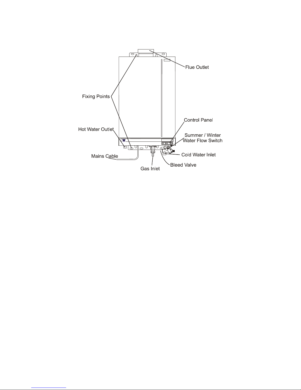
The WIDNEY RSW10KL is a wall hung, room sealed, fan assisted, microprocessor controlled fully modulating gas
Water heater for providing domestic hot water. It is particularly suitable for Caravan Holiday Home and Park Home
use. It is not suitable for road going vehicles.
DO’s and Don’ts
DO read the installation instructions before fitting the product
DO check that the correct gas and Water supply is available
DO use the recommended terminal and Flue Pipe
DO check that the flue system is correctly fitted prior to commissioning
DO NOT attempt to fit this appliance unless you are a qualified fitter
DO NOT operate this appliance before the installation checks are complete
Guidance Notes for POSITIONING AND LOCATION of Water Heater
1. WATER HEATER LOCATION
In positioning the water heater, the following limitations MUST be observed:
The position must allow for a suitable flue termination to be made.
The water heater must be installed on a flat vertical wall capable of supporting its weight. - If the water heater is in a
room containing a bath or shower, the water heater controls and power supply must be situated so that they cannot be
touched by the person using the bath or shower. Your attention is drawn to the current IEE Wiring Regulations, and in
Scotland the electrical provisions of the Building Regulations applicable in Scotland. - A compartment used to enclose
the appliance MUST be designed and constructed specifically for the purpose. An existing cupboard, or compartment,
may be used provided it is modified accordingly.
Please read the warnings located at the end of these instructions before proceeding with INSTALLATION.
2. FLUE TERMINAL POSITION
The heater must be installed so that the terminal is exposed to the external air.
It is important that the position of the terminal allows free passage of air across it at all times.
It is essential to ensure that the products of combustion discharging from the terminal cannot re-enter the building or
vehicle, through ventilators, windows, or other sources of natural air infiltration, such as other flues etc, with the
exception of doors, but not the opening windows thereof.
The minimum acceptable dimensions from the terminal to obstructions and ventilation openings are as follows:
Directly below an opening fixed vent or window etc................. 300mm
Adjacent to an opening fixed vent or window etc..................... 300mm
Below gutters........................................................................ 75mm
From a vertical drain pipe....................................................... 75mm
From an internal or external corner ........................................ 300mm

3
Where the terminal is fitted in a position to which children, the elderly, or disabled people have access (less
than 1.5m above steps, decking or ground), a suitable terminal guard should be fitted. In certain weather
conditions the terminal may emit a plume of steam.
• DO NOT MOUNT within 300mm vertically from a terminal on the same wall or horizontally from a terminal on
the same wall.
3. MINIMUM CLEARANCES
• Minimum clearances of 5mm to the front and sides of the heater must be observed. However full access from
the front in the form of an opening door, must be given to allow access to the controls and for servicing.
• 200mm above the top of the heater case is required for the flue assembly.
• 150mm is required below the heater to allow easy access to the gas isolation cock.
VENTILATION AND SERVICES REQUIREMENT
4. VENTILATION REQUIREMENTS
The following notes are for general guidance:
The Widney RSW10KL is a room sealed appliance and needs no purpose provided combustion air ventilation.
If the water heater is to be built into a small cupboard or compartment (i.e. at minimum clearances) and overheating
can be foreseen (i.e. close proximity to a cooking appliance etc.) permanent air vents are recommended for cooling
purposes in the cupboard or compartment.
5. ELECTRICITY SUPPLY
THIS APPLIANCE IS NOT DESIGNED TO BE USED WITH AN INVERTER, HOWEVER IF THERE IS NO OTHER
ALTERNATIVE THEN A PURE (TRUE) SINE WAVE INVERTER MUST BE USED.
• A 3 amp fused three pin plug and unswitched shuttered socket outlet (both complying with BS 1363 or
equivalent EN standard) or a 3 amp fused double pole isolator with a contact separation of 3mm in all poles
supplying only the heater should be used.
• Installation into a Bathroom – Please refer to the current IEE wiring regulations for installation and refer to the
data plate for product IP rating.
• THIS APPLIANCE MUST BE EARTHED
Where the product is fitted in a bathroom or an area that may be exposed to water spray please ensure that
appropriate electrical protection is provided to the mains connection.
6. GAS SUPPLY
The gas pipes must be copper. Do not connect plastic pipes directly to the heater. It is recommended that the copper
is extended to below the floor of the caravan/vehicle before connecting to plastic.
• Ensure the heater is set for the gas supply intended.
• A gas supply at the rating specified on the data label.
• Ensure the regulator is of sufficient capacity to carry the maximum water heater input plus the demand for any
other installed appliances.
• Ensure the connection between the supply/bottle and the caravan holiday home or park home is designed so
that no more than 2.4mbar of pressure drop occurs.
No more than 3 m of 15mm pipe should be used. Where the supply exceeds 3 m the pipe should be suitably
sized only reducing to 15mm before the water heater
• A full bore isolation valve must be fitted in the supply close to the water heater with either a union or
compression connection between the valve and the appliance to allow safe disconnection of the appliance.
• Connect the gas supply using a 15mm compression fitting.
• The complete installation must be tested for gas soundness.
7. CONNECTIONS TO WATER HEATER
The water pipes must be copper. Do not connect plastic pipes directly to the heater. It is recommended that the
copper is extended to below the floor of the caravan/vehicle before connecting to plastic.
• Ensure the water pipe complies with the requirements
• Remove any swarf or other residues in the pipes.
• Connect the heater using a 15mm compression tap connector fittings
• An isolation valve should be fitted to the inlet connection near to the appliance to allow service disconnection
of the appliance.
8. HOLIDAY HOME SERVICES
• Ensure that the pipe sizing and connections between the supply/bottle regulator and the caravan/vehicle is
designed so that no more than a maximum pressure drop of 2.5mbar occurs.
• This appliance must be fitted with an isolation valve not supplied.
• A cold water supply with a working pressure of a minimum of 0.18 bar measured at the cold water inlet to the
heater is required. Wherever possible the cold supply to the heater should be the first connection off the main
supply in order to minimise hot water flow reduction when cold water services are called for.
4
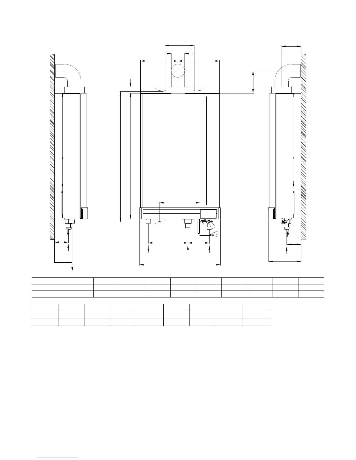
APPLIANCE DIMENSIONS:
A
C
D
B
E
F
G
I
J
M
N
O
P
K
L
GAS
GAS
H
Q
MODEL
A B C D E F G H I
RSW10kl side flue
360 572 135 60-100 25 65
130 180 590
RSW10kl rear flue
360 572 165 60-100 25 95 130 180 590
J K L M N O P Q WEIGHT
40 35 55 175 90 125 187 168 13.6kg
70 65 85 175 90 125 187 168 13.6kg
5
Diagram Bi
INSTALLATION PROCEDURE
9. UNPACKING
The Water heater is supplied in a separate carton. Care should be taken when unpacking to ensure there is no
damage to the product.
Included in the Water heater carton are :- Installation and User instructions, Gas isolation valve & 100mm of 15mm dia
Copper tube.
In a separate pack: Flue kit – comprising of Inlet and outlet rigid tube – Terminal – Elbow - Clamping Rings (2) –
Sealing Collars (2).
THE WATER HEATER MUST BE INSTALLED WITH THE SUPPLIED FLUE KIT
10. SELECTING THE POSITION
Decide where the heater is to be fixed taking into account the installation requirements required under the relevant
standards and sections 1, 2,3,12 of these instructions.
11. WALL MOUNTING
The Water Heater can either be mounted with the flue system exiting to the rear or side of the appliance. For
Wall mounting with flue to the rear refer to paragraph entitled ‘Flue installation to the rear’.
Materials around the flue system – The outer flue will reach a maximum
temperature rise of 35oC. Care should be taken in ensuring that any materials
touching the outer flue are capable of withstanding this temperature for extended
periods. It is recommended that the rubber inner and outer seals are pushed into
the wall aperture before sealing. This will ensure that the outer flue pipe fits
centrally in the wall aperture.
Flue installation to the side: See diagram Bi
The water heater should be mounted on a suitable wall with sufficient structural strength
to ensure adequate support.
1. Mark the position of the fixing holes and the outlet aperture in the wall as
indicated in diagram Bi. Ensure that the position of the flue outlet meets with the
requirements of the relevant standards and is located as detailed in section 2.
2. Cut the hole for the flue liner through the wall of the home.
3. Fix the flue system to the water heater see section 12.
4. Fix the water heater securely through the fixing brackets located at the base
and top of the unit.
5. Go to section 12.
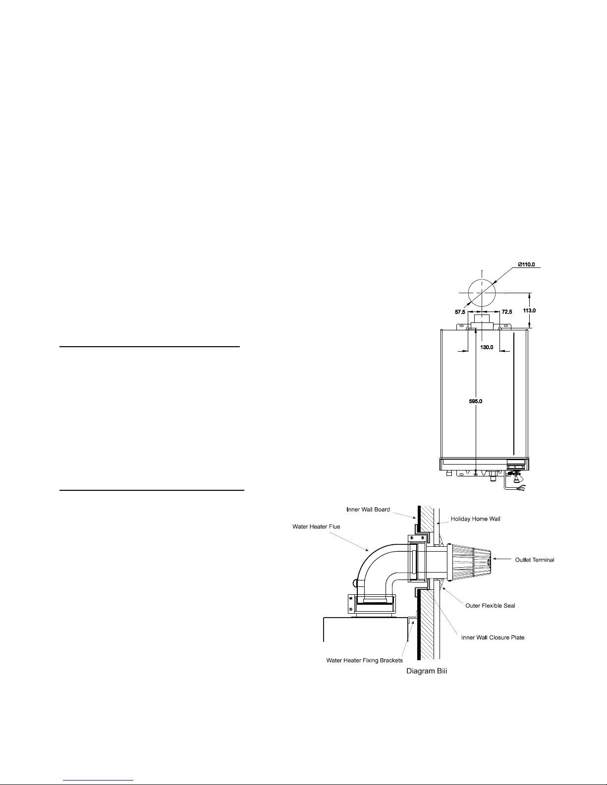
Flue installation to the rear: See diagram Biii
This method of installation requires a fixing kit part
no. RSWFIX01. The fixing kit comprises of two fixing
brackets to replace the fixing brackets fitted to the
water heater and a wall closure plate.
The water heater should be mounted on a suitable
wall with sufficient structural strength to ensure
adequate support.
1. Mark the position of the fixing holes and the
outlet aperture in the wall as indicated in
diagram Bi. Ensure that the position of the
flue outlet meets with the requirements of
the relevant standards and is located as
detailed in section 2.
2. Cut the hole for the flue liner through the
wall of the home.
3. Align the closure plate with the hole in the
inner wall and mark around the closure plate.
4. Cut out the inner section of the wall to fully recess the inner wall closure plate diagram Biii.
5. Insert the closure plate into the wall opening and fix with suitable fixings.
6. Fix the flue system to the water heater see section 12.
7. Go to section 12.
6
12. FLUE INSTALLATION
Positioning:
• The water heater MUST be installed so that the terminal is exposed to the external air.
• It is important that the position of the terminal allows free passage of air across it at all times.
• It is ESSENTIAL TO ENSURE, that products of combustion discharging from the terminal cannot re-enter the
building, or vehicle, through ventilators, windows, or other sources of natural air infiltration, such as other flues
etc, with the exception of doors, but not the opening windows thereof. The minimum acceptable dimensions
from the terminal to obstructions and ventilation openings must be as detailed in section 2.
Installing the flue system:
IMPORTANT
The standard horizontal flue kit supplied with the RSW10KL is part number RSWFK1M. This kit provides for 1
meter of flue length and one 900 elbow. Note: DO NOT INSTALL THIS APPLIANCE WITH MORE THAN ONE 90
0
Elbow (Bend) and more than 1.0 metre of flue length.
Never use a flue kit not specifically approved for use with this appliance.
NOTE: Where the home is pre-installed with the RSW10KL please consult the home manufacture for
replacement part numbers.
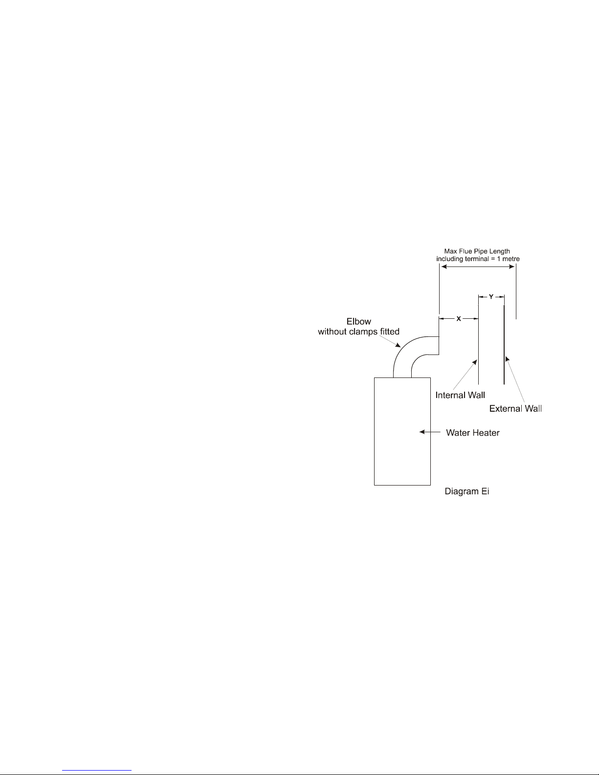
NOTE: The inner flue pipe of the terminal must be cut
accurately and must always be 100 mm longer than the outer
flue in order to ensure correct location in the terminal and
elbow. NOTE: The outer pipe has two holes at one end to
fix the terminal always cut the pipe at the opposite end to
these two holes.
To calculate the correct length of the outer flue use the
following formula and refer to diagram Ei
Formula: dimension X + Y + 20 mm (Note Dimension X is
the distance between the inner wall of the home and the
end of the elbow without the sealing collar attached; in
the case of rear flue installation the appliance should be
fitted with installation Kit RSWFIX01 if this kit is used
then the dimension X = 10mm.)
For calculating the inner flue lengths use the overall length of
the outer flue liner when cut to size and add 100mm.
Two sealing collars are provided to seal the external pipe
against the internal and external wall.RSWSC01.
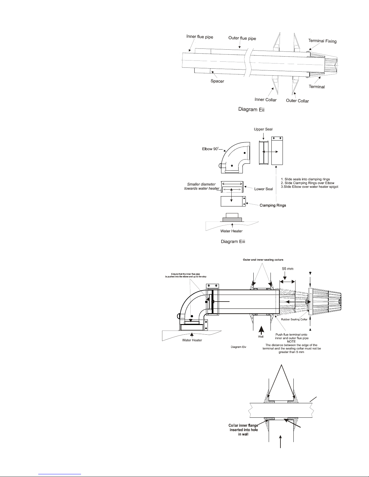
The flue assembly must be installed with a slight downwards
incline of 20 towards the terminal to prevent the ingress of rain water, which may damage the heater. See diagram Eii.
Terminal Guard: if the position on the outlet terminal is less that 2 meters above ground level it is recommended that
a terminal guard be fitted.
7
Connecting the flue system:
Refer to diagram to assist in assembly.
1. Slide the inner flue pipe into the outer flue
pipe ensuring that the spacer on the inner flue
pipe is evenly positioned - Note for flue
lengths less than 300 mm the spacer is not
required, see diagram Eii.
2. Fit the clamping rings onto the elbow. Note:
ensure that the smaller diameter of the
clamping ring seal is facing the water
heater outlet spigot, see diagram Eiii.
3. Connect one end of the elbow to the water
heater and secure the clamping ring.
4. Slide the inner flue pipe into the elbow then slide
on the inner rubber collar over the flue pipe and
insert the outer flue pipe through the clamping
ring and into the elbow the secure the clamping
ring, see diagram Eiv.
Note: if fitting rear flue the inner rubber collar
should not be fitted.
Note; the inner flue pipe must protrude 55 mm
beyond the outer flue pipe, see diagram Eiv.
8. Fit the water heater to the wall by inserting the
flue pipe through the hole in the wall and
securing the water heater through the fixing
brackets into the pre drilled holes as detailed in section 11.
5. On the outside of the home slide the
outer collar over the outer flue pipe.
6. From the outside of the home locate the
terminal onto the inner flue pipe ensure
that the rubber seal is fitted to the
terminal before fixing to the flue pipe
then push the terminal over the outer
flue pipe.
NOTE The maximum gap on Fig Eiv
ensure that the inner flue pipe is
correctly aligned in the elbow on the
water heater before pushing on fully.
When the terminal is in the correct
position the holes in the terminal will align with the holes in the
outer flue pipe. Secure the terminal to the outer flue pipe with the
fixings provided.
7. If applicable slide the inner collar up to the inner wall and seal
with sealant. See diagram Evi
8. Slide the outer collar up to the outside wall and seal with sealant.
Outer and Inner sealing collars
Wall
Air Gap
Diagram Evi
Outer Flue
Note: 2° down
8
INSTALLATION COMPLETION
13. WIRING
Observe all the usual precautions to ensure that the electricity supply is isolated before beginning any installation
work. The heater should be wired as described in section 5.
Important: this appliance must be earthed.
14. GAS AND WATER CONNECTIONS
Connect the gas and water connections to the appliance using the appropriate fittings. Ensure that the pipe sizing,
material and connections comply with sections 6, 7, and 8 of this manual.
SETTING AND FIRST USE
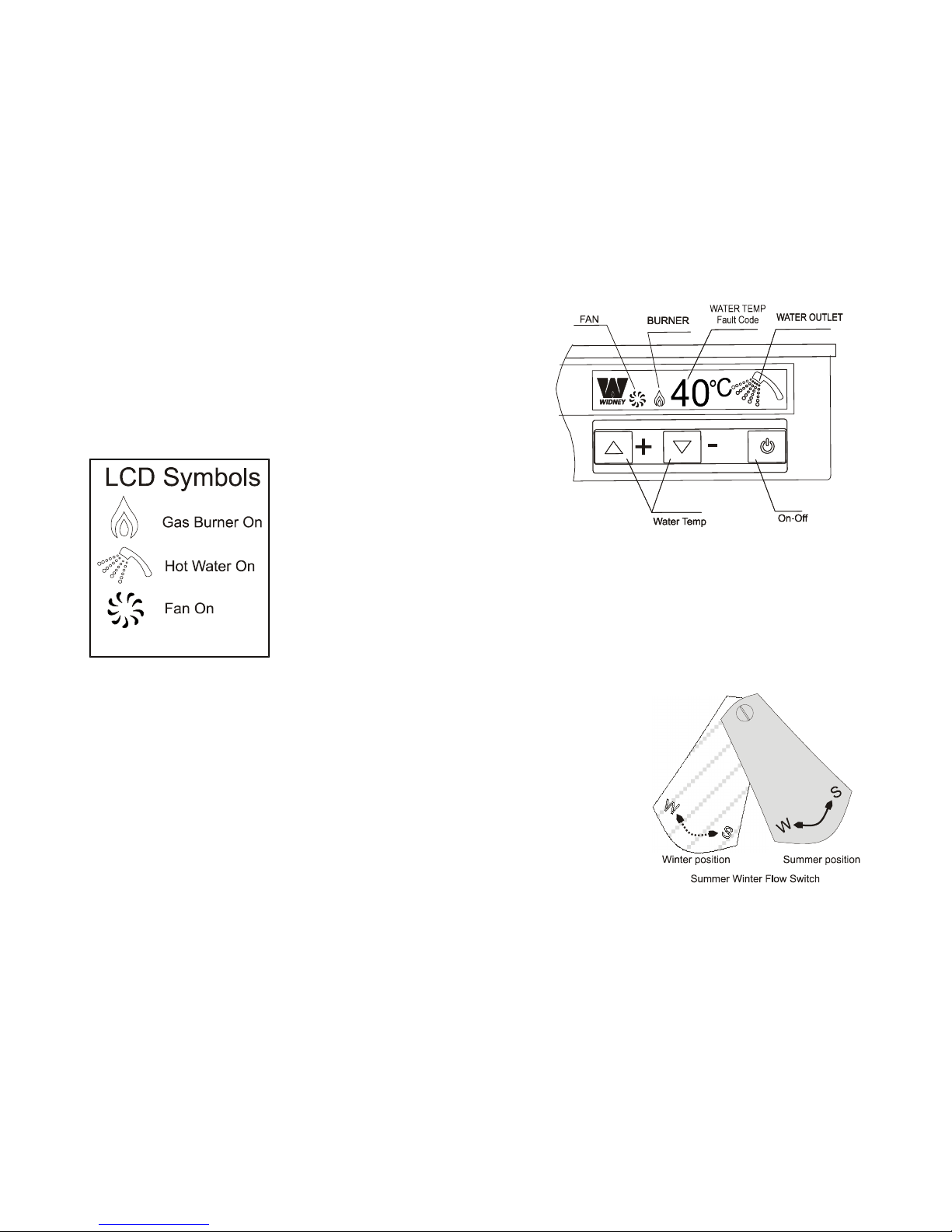
15. THE CONTROL SCREEN
The control screen displays the water temperature, fan operation,
burner operation and water delivery and fault diagnostics information.
In normal operating conditions the screen will display the set water
temperature and operational mode, for example if the water heater is
not being used the temperature will be displayed together with a
shower head. If the water heater is working then the shower head will
display a water effect and the burner and fan will flash on and off.
The temperature of the water that will
be delivered from the appliance is set
by using the up and down buttons on
the left hand side of the panel.
To operate the water heater turn on the power from the mains – (the control panel will
light up and display the number 18 which confirms that PCB mode and settings are
correct for this appliance, the display will then go to a non-illuminated condition), then
switch on the water heater via the on—off switch on the control panel. The water heater
is now in operational mode and will automatically start up when the hot water tap is used.
Water temperature can be set between 350C and 650C it recommended that the optimal
temperature is 400C
16. GENERAL GUIDANCE NOTES ON HOT WATER DELIVERY
The temperature of the hot water is governed by both the ambient temperature of
the cold water supply and its flow rate through the water heater. The flow rate of the
hot water is controlled by the hot outlet tap / shower.
Water Flow settings: The appliance is fitted with a manual water flow adjuster which
should be in the summer position for normal operation; however in very cold
conditions the water inlet temperature may be too low to heat the water effectively. If
this happens then the water flow switch should be set to the winter position.
The water heater can theoretically supply more than one outlet simultaneously;
however in practice the tap which is nearest will receive the most hot water. If the
shower is in use and a kitchen tap is opened virtually all the hot water will be
diverted to the kitchen as it offers the least resistance.
• Due to the restrictive nature of simple mixer showers it is wise to turn the temperature selector down on
the water heater before using the shower.
DO NOT PLACE YOUR HANDS under the tap or use the shower until this initial flow has passed.
Allow time (30 seconds) for the temperature to stabilise after making an adjustment at the tap before making further
adjustments.
17. APPLIANCE SAFETY LOCK-OUT
This water heater has a fault indicator built in to it on the front display, whenever a malfunction is detected in the water
heater the display panel will indicate a fault code and turn the water heater off. Please refer to the fault code section to
diagnose a fault.

9
COMMISSIONING ENGINEER AND END USER FAULT CODES
Fault
Code
Problem Identified Action to take
E0
Input Water Temperature sensor
Fault
Switch off mains power supply – then restart by switching mains supply on and
pressing the on off button on the control panel – If problem persists contact
service
E1 Ignition Failure / No Flame Detected
Switch off mains power supply
Check gas supply and gas pressure at appliance
Restart by switching mains supply on and pressing the on off button on the
control panel
– If problem persists contact service
E3
Blocked Flue—Abnormal wind
Condition
Switch off mains power supply
Check for blockage around outlet terminal
Leave for 30 minutes then restart by switching mains supply on and pressing
the on off button on the control panel – If problem persists contact service
E4 Fan or Power Fault
Switch off mains power supply –
Check mains supply and fuse
Restart by switching mains supply on and pressing the on off button on the
control panel – If problem persists contact service
E5
Outlet water temperature too high /
Over Temperature Protection
Switch off mains power supply –
Check flow of water supply to water heater
Switch on
Check temperature setting on water heater.
Turn to full and re test for temperature.
Turn Winter summer water valve to summer setting.
Switch off mains power supply
Restart by switching mains supply on and pressing the on off button on the
control panel – If problem persists contact service
E6
Water Outlet temperature sensor
failure
Check temperature setting on water heater.
Turn to full and re test for temperature.
Turn Winter summer water valve to winter setting.
Switch off mains power supply
Restart by switching mains supply on and pressing the on off button on the
control panel – If problem persists contact service
E7 DIP Switch incorrect setting
Factory Setting incorrect.
Switch off mains power supply
Switch of gas and water supply
Turn on all services
Restart water heater.
If problem persists contact service
F0 Power on start-up failure
Water is flowing through heater on power up.
Ensure water is NOT flowing through heater when power supplied.
Reset by turning off power and ensure all taps and shower are turned off. Repower water heater to clear fault code.
 Loading...