

Widney Revo Installation Instructions Manual
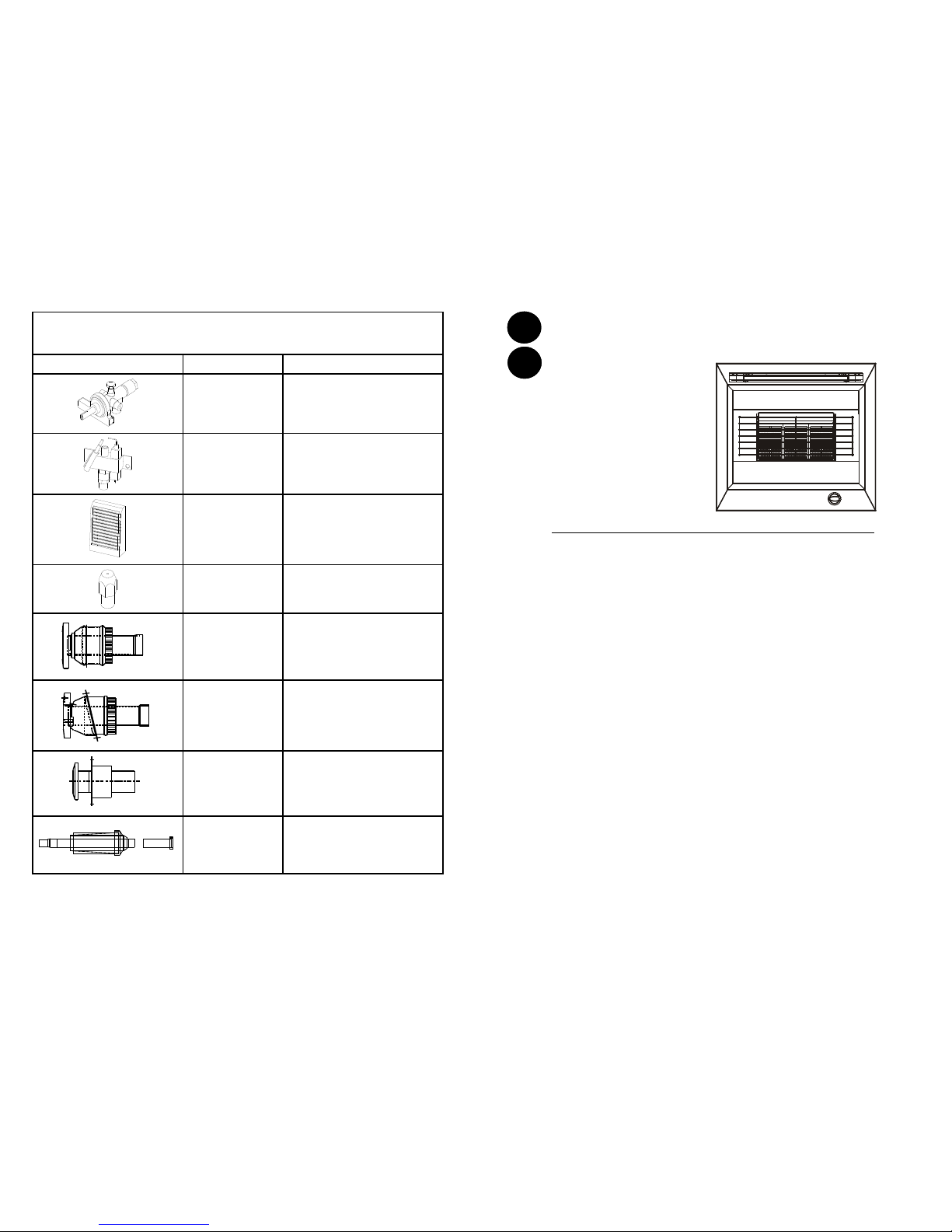
SHORT PARTS LIST
The illustrated short parts list incl udes part numbers.
When ordering quote gas fir e name with part number & descr iption.
Gas Train
PART NUMBER DESCRIPTION
W00018
W00166
Control Valve with rotary igniti on
(LPG)
Control Valve with rotary ignition
(NG)
W00020
W00170
Oxygen depletion device / pilot
assembly (LPG)
Oxygen depletion device / pilot
assembly (NG)
RA002 Radiant (pack of 3)
W00028
W00167
Burner Injector (LPG)
Burner Injector (NG)
W99901
Straight Terminal with Vent
Plain Finish.
For other finishes please contact
customer services
W99801
Angled Terminal with Vent.
Plain Finish.
For other finishes please contact
customer services
W99600
Straight Terminal Non Vented.
Plain Finish.
For other finishes please contact
customer services
W00213
Terminal with Vent
Pantile Roof
For other finishes please contact
customer services
8
Part Number: W00317 Issue E
GB
IE
INSTALLATION & MAINTENANCE INSTRUCTIONS
READ THESE INSTRUCTIONS BEFORE INSTALLING OR SERVICING THE FIRE
IMPORTANT: Before installation ensure that the local distr ibution conditions (ident ified by
the type of gas and pressure) and the adjustment of the appliance are compatibl e.
Revo Natural gas version.
The appliance is suitable f or use with G20 natural gas at a supply pressure of 20mbar f or categories
I2H & I2E and additionally G25 at a su pply pressure of 25mbar (pr essure couple operates) in the c ase
of category I
2E+
& I2L.The following lists all EC m ember states, which have a suit able gas supply for
each category designation:
I2H:- AT, CH, CZ, DK, ES, FI, G B, GR, IE, IT, NO, PT, SE, EE, LT , LV, SI, SK
I2E:- DE, LU - I
2E+
:- BE, FR—I2L:- NL
Revo LPG gas version.
The appliance is suitable f or use with G30 Butane at a supply pr essure of 28-30 mbar and G31
Propane at a supply pressure of 37 mbar for category I
3+.
It is also suitable for G30 But ane and
G31 Propane at a supply pr essure of 30mbar for I
3B/P
The following lists all EC memb er states, which have a suitabl e gas supply for each categor y
designation:
I
3B/P
:- CZ, FI, NL, NO, SE, LT, LV, SI, SK
I 3+:- BE, CH, CZ, ES, FR, GB, IE, IT, PT, EE, CY
It is a legal requirement that all gas appliances are installed by a c ompetent person in accordanc e
with the Gas Safety Installati on and Use Regulations 1994.
Failure to install the applianc e as stated can lead to prosecution, i t is in your interests
that the law is complied with.
Installation and Ventilation requir ements shall be in accordance with these Installation Instructi ons,
BS EN 1949:2002, BS EN 721:1 999, BS5871 and BS EN 16 47:1999.
For the Rep ublic of Irelan d the installation must be carried ou t by a competent p erson and also c onform to the rele vant par ts of :
The current edition of IS 81 3—Domestic Gas Ins tallations
All relevan t national and loca l rules in force
WIDNEY L EISURE LTD.
SAXON BUSINESS PARK, HANBURY ROAD,
STOKE PRIOR, BROMSGROVE,
WORCESTERSHIRE B60 4AD. ENGLAND
TELEPHONE: + 44(0)1527 577800
Email: sales @widney-leisure .co.uk Web: www.wi dney-leisure.co .uk
1
WIDNEY
Revo
Gas Fire
All Model Variants
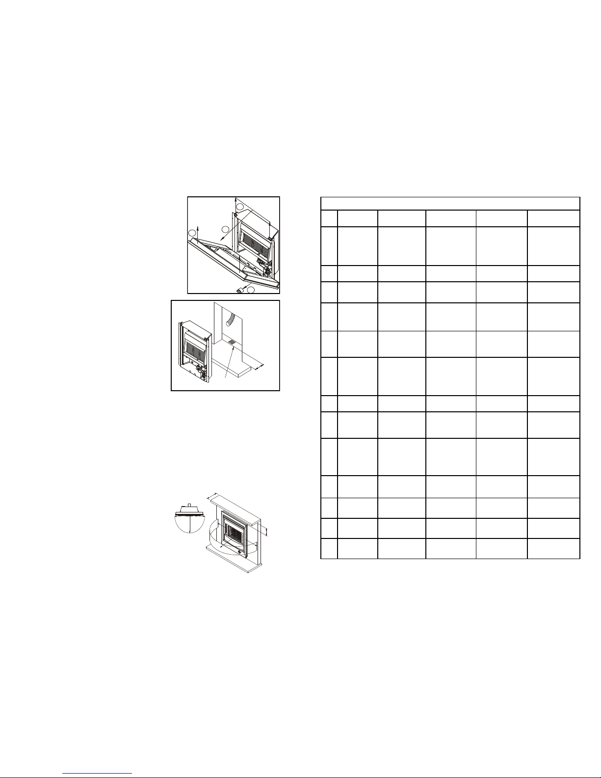
PREPARATION OF THE FIRE:
Note: Before commencing installation it is recommended that
you fill in the appliance details on the rear of the user’s
instruction.
REMOVAL OF THE FIRE FRONT:
Remove the control knob fr om the gas valve by pulling in the
direction of the arrow. Lift the fr ont upwards approximately
10mm to clear the top location brackets taking care not to dist ort
or damage the top louvre vents
Pull the top of the front forw ard approximately 50mm then lif t
clear of the locating tabs in th e base of the fire. (See Fig 1)
REPLACING THE FIRE FRONT:
Reverse the above procedur e taking care to locate the
upturned tabs on the base panel into the slots in the lower
panel return flange on the fire front.
LOCATION:
When locating the fire ensure that the minimum thermal lift of
1690mm as indicated in figure 4 can be achieved.
PREPARING THE APERTURE:
Cut an aperture in the furniture to t he following
dimensions: 560mm High x 440 mm Wide, this ensures a
minimum 5mm air gap between th e fire back and the
furniture is maintained.
It is recommended that the bas e of the fire is supported
and no room air is allowed t o enter the cavity from under
the fire base (See fig 2).
FITT ING THE FIRE :
The fire must only be fitted with recommended flue liner and terminals - please consult the supplier for
further information. The flue liner needs to be prepared prior to fitting. Refer to these instructions and Fig 4
for this stage.
Depending on the construction of the flue cavity, the flue liner can be installed before or after the fire back is
fastened into position. In any installation, the flue liner must be pushed fully over the fire back flue spigot
and secured to the fire and Terminal spigot using steel self-tapping fasteners which will retain the liner into
full position to the terminal/fire spigots. Under no circumstances must the liner be left installed without a
sound connection and the position unfastened.
The fire should be installed as fig 3 with self tapping screws through the 2 fixing brackets on the sides of the
main fire chassis to the fire surround.
Any materials, coatings or finishes used in the construction of the fire surround and hearth must be
specified to tolerate the full radiated and convected and conducted heat from the fire.
POSIT ION OF C OM BUSTI BLE MAT ERI ALS:
It is recommended that no fixed combustible materials are
located within 500mm of the centre line of the fire – measured
from the centre radiant. Any combustible materials used for
the construction of the fireplace that are not subject to direct
line of sight to the ceramic radiants must be able to tolerate
the radiated, conducted and convected heat of the appliance
when operated at full rate. The materials used must comply
with the relevant British or EN standard / Code of Practice for
this installation. Note: It is the responsibility of the installer to
ensure that any material used adjacent to or adjoining the
appliance is fit for purpose. Any loose furnishings should not
be placed within the dimensions as indicated in (Figure 3)
1
2
3
4
Fig 1
Fig 2
Ensure that the Hearth
extends under the Fire
120mm
minimum
Fig 3
100mm
Maximum
100mm
Minimum
500mm
A 500mm line should be
taken from the centre of
the Fire Radiants to a part
500mm in front of the fire
500mm
2
7
WIDNEY LEISURE GAS FIRE TROUBLE SHOOTING TABLE
Fault Action I still hav e a
problem
Action I still ha ve a
problem
1 Fire will Not
Ignite
Check gas pressure
at fire
If pressure is correct
see item2
See trouble shooting
headings for further
assistance: If Fault
not listed contact:
Widney Leisure Ltd
Customer service
2 The pilot does
not spark
Check spark Gap Spark Gap is correct
but has no spark
Replace gas valve
and pilot assembly.
As Above
3 Fire Ignition
Sparks but does
not light
Check pilot jet for
blockage
Pilot is clear but no
gas coming through
Check Main Gas
Valve for blockage
As Above
4 Pilot light
ignites but
main burner
does not ignite
Check main
injector for
blockage
The main injector is
clear but the fire
does not ignite
Check Main Gas
Valve for Blockage
As Above
5 Main burner
ignites but
flame is very
low
Check main
injector for
blockage
The main injector is
clear
Check for blockage
in main gas valve
and pipe work
As Above
6 The main gas
valve is
blocked
Replace gas valve See trouble shooting
headings for further
assistance: If Fault
not listed contact:
Widney Leisure Ltd
Customer service
7 The gas feed
pipe is blocked
Replace gas feed
pipe
As Above
8 Ceramic
Radiant turning
black
(Sooting)
Ensure that no
direct draft is
entering the fire
There are no drafts
around the fire
Check to ensure
radiants are correctly
fitted
As Above
9 The main
burner is
blocked
Replace burner See trouble shooting
headings for further
assistance: If Fault
not listed contact:
Widney Leisure Ltd
Customer service
10 Fire burns with
yellow flame
Ensure that no
direct draft is
entering the fire
There are no drafts
around the fire
Check main injector
for blockage
Contact Widney
Leisure Ltd Customer
service
11 Fire Flame
fluctuates
Ensure that no
direct draft is
entering the fire
There is a draft from
the rear of the fire
Contact:
Widney Leisure Ltd
Customer service
12 Fire appears to
be overheating
Check gas pressure
at fire
The gas pressure is
correct
Contact:
Widney Leisure Ltd
Customer service
13 Fire does not
get hot enough
Check main
injector for
blockage
The injector is clear Check gas pressure
at fire
As Above
 Loading...