

Page 1

OWNER’S MANUAL
OPERATING INSTRUCTIONS
Page 2

Thank You For Choosing the Wi Digital System.
Congratulations on your purchase of the Wi Pro AudioMatrix 2.4GHz Stereo Digital Multicast Wireless Audio
System for DJ Gear & Active Loud Speakers
Please thoroughly read this User’s Manual for all the feature operation information necessary
to install and operate your new Wi Pro AudioMatrix system.
Notice: Product specications and package contents are subject to change without notice.
Package contents may vary according to the different regions.
For additional support, please visit www.widigitalsystems.com
CONGRATULATIONS!
Page 3

3
TABLE OF CONTENTS
------------------------------------------------------------------------------------------
------------------------------------------------------------------------------------------
------------------------------------------------------------------------------------------
------------------------------------------------------------------------------------------
------------------------------------------------------------------------------------------
------------------------------------------------------------------------------------------
------------------------------------------------------------------------------------------
------------------------------------------------------------------------------------------
------------------------------------------------------------------------------------------
------------------------------------------------------------------------------------------
------------------------------------------------------------------------------------------
------------------------------------------------------------------------------------------
------------------------------------------------------------------------------------------
------------------------------------------------------------------------------------------
------------------------------------------------------------------------------------------
------------------------------------------------------------------------------------------
------------------------------------------------------------------------------------------
------------------------------------------------------------------------------------------
------------------------------------------------------------------------------------------
------------------------------------------------------------------------------------------
------------------------------------------------------------------------------------------
Page 4

TECHNICAL SUPPORT
Getting Answers!
We want you to get the most from your new Wi Pro AudioMatrix stereo digital wireless audio system!
Simply logon to www.widigitalsystems.com and access the resources available online including
instructional manuals and more.
Our customer service support staff are ready to assist you with any question you may have.
Your Wi Pro AudioMatrix comes with 90 days of telephone support and one year of service coverage.
There are may ways to contact Wi Digital Systems customer service support.
E-Mail: support@widigitalsystems.com
Website: www.widigitalsystems.com/support
Technical support: (714) 505-4567
4
Page 5
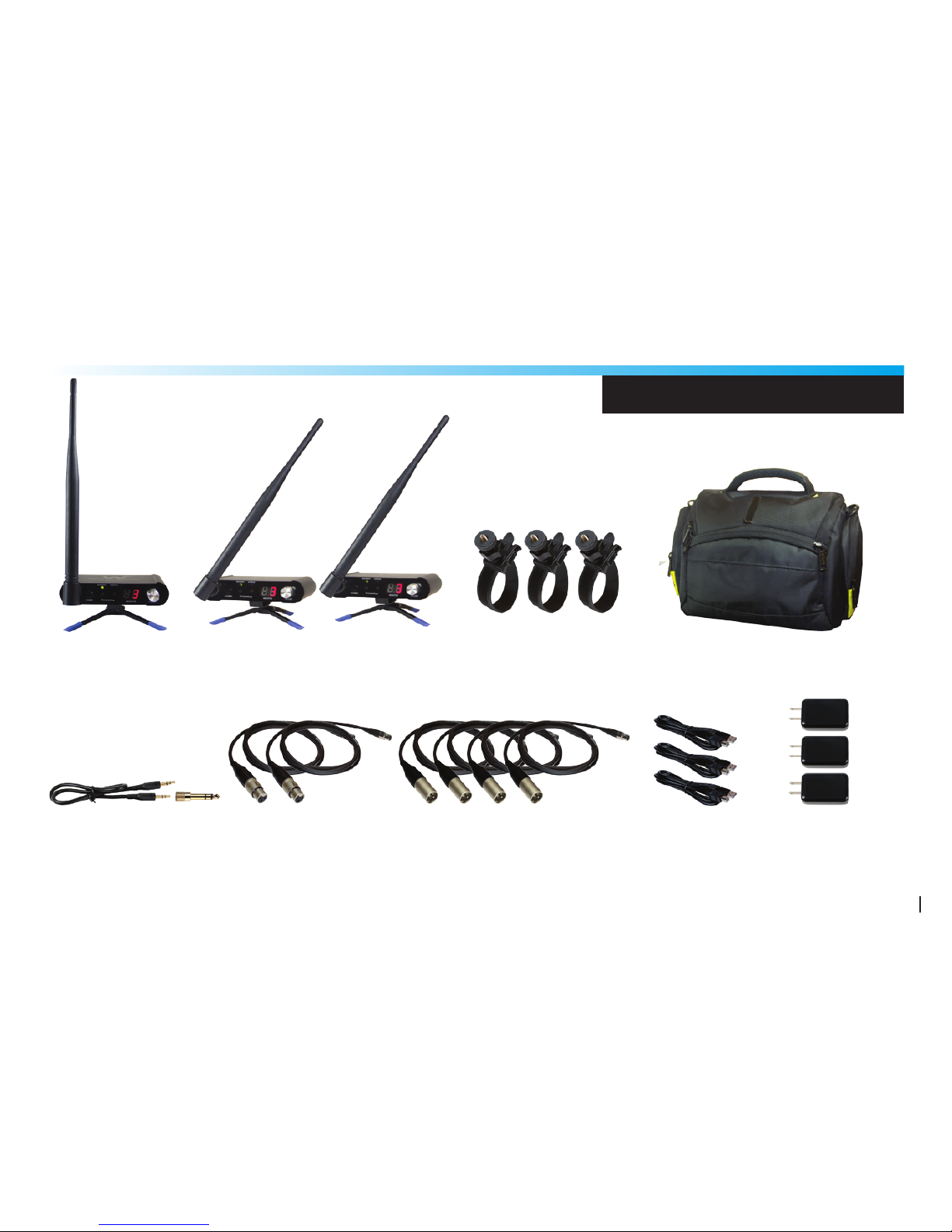
PACKING LIST
Wi Transmitter with
1/4”-20 Tripod Stands (x1)
Wi Receivers with
1/4”-20 Tripod Stands (x2)
Mini XLR to Male XLR
Stereo Cables (x4)
1/8” to 1/8” TRS Stereo
Cable & 1/4” Adapter (x1)
Mini XLR to Female
XLR Stereo Cables (x2)
Carrying Case (x1)
Universal USB
Power Adapters (x3)
5
USB Power
Cables (x3)
Universal Mounting BracketsFor
Speakers & Stands (x3)
Page 6

• Elegant Simplicity, Superior Sound, Professional Dependability
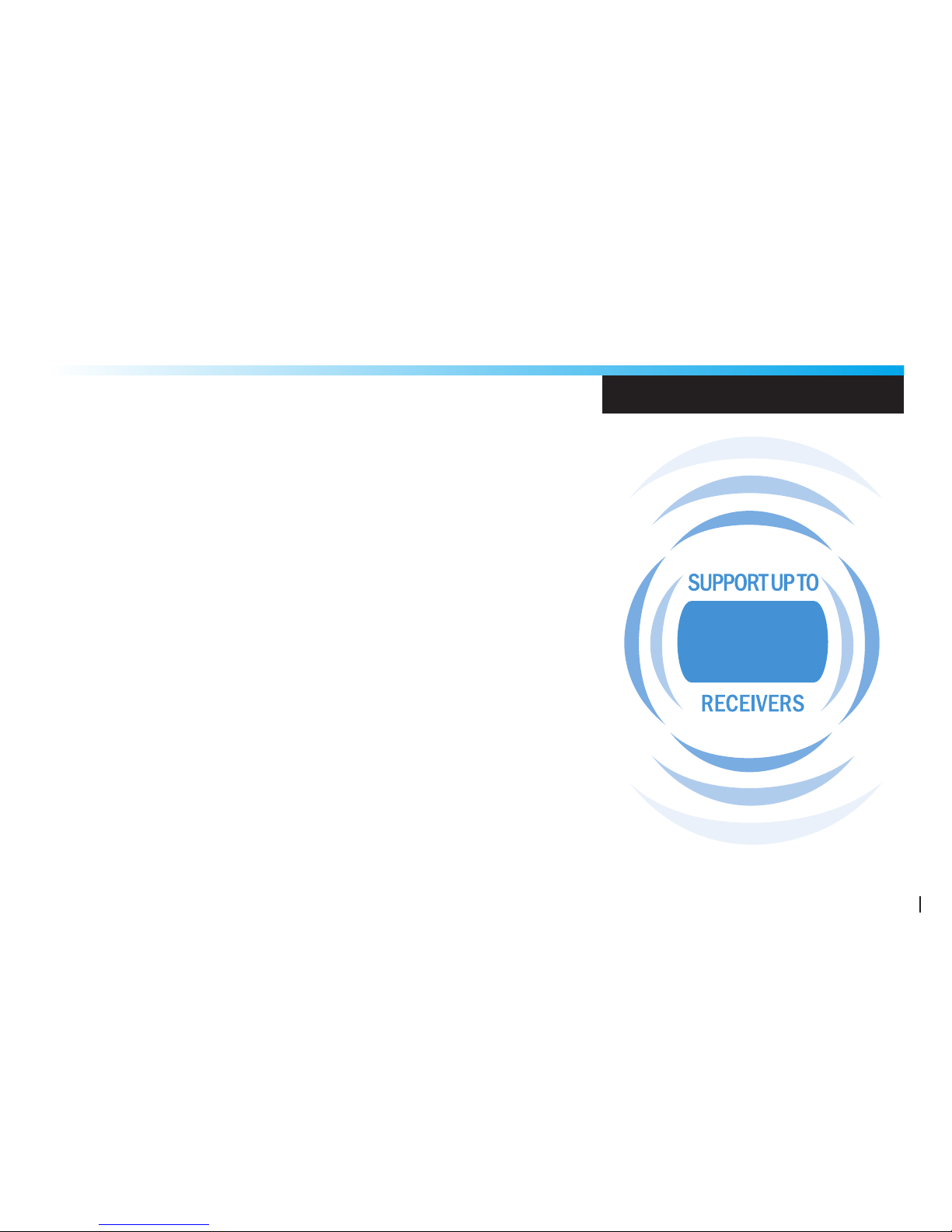
The Wi Pro AudioMatrix WI-AMP50 is designed to enable users to create a
stereo digital wireless audio distribution matrix fromone transmitter to up to
50 digital wireless receivers without the need to route cables to speakers.
• Wi Digital’s Seek-and-Link Technology
Designed to look, sound and congure like no other pro audio wireless system.
This elegant plug-and-play system features Wi Digital’s Seek-and-Link algorithms
that enable receivers to search for audio stream acquisition and automatically
link to the transmitter, rendering manual pairing a thing of the past!
• Rugged Construction, Secure Mount, Portable Design
The Wi Pro AudioMatrix transmitter and receivers are engineered with a super
strong aluminum chassis and universal mounting metal belt clip with a 1/4”-20
screw mount that can be securely or permanently attached to the speakers and
and DJ gear, including stands, tripods and bipods for elevated and unobstructed
line of sight setups.
SYSTEM HIGHLIGHTS
6
Page 7
• Extreme Power Flexibility
The Wi Pro AudioMatrix power source’s exible design boasts an
internal rechargeable battery for 6~8 hours of battery operation.
Add a standard USB AA battery adapter for up to 20 hours of
extended use. No need to power down the system to charge or
replace the batteries.
There’s also an AC power adapter for continuous operation.
You can even use USB bus power to charge and operate your
Wi Pro AudioMatrix. Enjoy true freedom from power concerns.
• All Accessories Included!
This combination of portability, simplied setup and all required
accessories, including mounting kits and high quality cables,
lets you set up quickly and easily!
SYSTEM HIGHLIGHTS
50
7
Page 8

8
Transmitter Front Panel
j Antenna: Detachable High Perroance Antenna
k Antenna Port: Place the antenna in a vertical position for best wireless transmission results
If the wireless signal quality is poor, change the position of the antennas.
l Power ON/OFF: Press and hold the Power button for 2 seconds to turn the transmitter ON or OFF
m Channel Slelect: Adjusts the frequency band range. Press the up or down buttons to select a channel
n Battery LED: Displays the status of three functions. Full Battery, Low Battery and Charging.
o Status LED: The LED will turn RED when the wireless signal is lost and GREEN when the wireless
signal is eastablished
p Monitor Display: Displays the status of three functions. Channel Number, Volume Level and Mute Status
q Volume Control: Rotate teh dail clockwise for volume up and counter clockwise for volume down.
Press and hold the dail for 1.5 seconds to mute or un-mute the audio transmisson.
TRANSMITTER FEATURES
Page 9

9
TRANSMITTER FEATURES
k
j
l n o
m
p q
Page 10

10
TRANSMITTER FEATURES
Transmitter Rear Panel
j Gain Select: Selectable gain levels -20 dB, 0 dB and +20 dB
k Stereo Input: 1/8” TRS stereo input port
l Left Channel: Left channel audio input port (Mini XLR Balanced)
Connect this XLR input to the input of your mixer
m Right Channel: Right channel audio input port (Mini XLR Balanced)
Connect this XLR input to the input of your mixer
n Power Input: 5V DC, 500 mA (USB Bus Power)
Connect the included 5V DC, 500 mA power supply here
o Belt Clip: Metal Belt Clip & 1/4”-20 Screw
Connect this port to the supplied mounting accessories for table top setups
or speaker and stands setups.
Page 11

11
TRANSMITTER FEATURES
o
j k n m l
1/4”-20 Screw
Page 12

12
RECEIVER FEATURES
Receiver Front Panel
u Antenna: Detachable High Perroance Antenna
v Antenna Port: Place the antenna in a vertical position for best wireless transmission results
If the wireless signal quality is poor, change the position of the antennas.
w Power ON/OFF: Press and hold the Power button for 2 seconds to turn the transmitter ON or OFF
x Channel Slelect: Adjusts the frequency band range. Press the up or down buttons to select a channel
y Battery LED: Displays the status of three functions. Full Battery, Low Battery and Charging.
z Status LED: The LED will turn RED when the wireless signal is lost and GREEN when the wireless
signal is eastablished
{ Monitor Display: Displays the status of three functions. Channel Number, Volume Level and Mute Status
| Volume Control: Rotate teh dail clockwise for volume up and counter clockwise for volume down.
Press and hold the dail for 1.5 seconds to mute or un-mute the audio transmisson.
Page 13

13
RECEIVER FEATURES
v
u
w y z
x
{ |
Page 14

14
RECEIVER FEATURES
Receiver Rear Panel
u Gain Select: Selectable gain levels -20 dB, 0 dB and +20 dB
v Stereo Output: 1/8” TRS stereo output port
w Left Channel: Left channel audio output port (Mini XLR Balanced)
Connect this XLR output to the input of your speaker
x Right Channel: Right channel audio output port (Mini XLR Balanced)
Connect this XLR output to the input of your speaker
y Power Input: 5V DC, 500 mA (USB Bus Power)
Connect the included 5V DC, 500 mA power supply here
z Belt Clip: Metal Belt Clip & 1/4”-20 Screw
Connect this port to the supplied mounting accessories for table-top setups
or speaker and stands setups.
Page 15

15
RECEIVER FEATURES
z
u v y x w
1/4”-20 Screw
Page 16

16
Wi Pro AudioMatrix Technical Specications
System Specications
Transmission Format: 2.4 GHz, 16-bit, 48kHz Digital Wireless
Frequency Response: 15Hz to 20kHz
Frequency Selection: Auto select
S/N Ratio: More than 96 dB (A-weighted) for stereo line-in mode
More than 89 dB (A-weighted) for stereo and mono MIC mode
Distortion: 0.12 % THD
Connectors: 1/8” (3.5mm) TRS Stereo
Max Input Level: 1Vrms
Max Output Level: 1.2Vrms
Input Impedance: 3.3K ohm
Output Impedance: < 10 ohm
Rechargeable Battery Life: 4~6 hours
Power Input: 5V DC, 500 mA
SYSTEM SPECIFICATIONS
Page 17

17
Specications
Battery Power Booster: 10~13 hours (With optional AA battery power booster adapter)
USB Bus Power: Yes
Low Battery Alert: 15 minutes of life left
Power-up Modes: Three (3) power-up modes (Stereo Line-in, Stereo Mic-in, Mono Mic-in)
Antenna: Two internal antennas
Range: Up to 250 ft
(Range may be dependent on line of sight and may vary due to local conditions)
Units operating at the same time: 9
Transmitter Weight: 0.068 lbs (1.08 Oz) (30.8g)
Receiver Weight: 0.068 lbs (1.08 Oz) (30.8g)
Dimensions: 1.2” W x 0.6” D x 3.34” H
Mounting Method: Metal belt clip
SYSTEM SPECIFICATIONS
Page 18

18
Charging The System
Before using your new Wi Pro AudioMatrix™ digital wireless system,
you need to fully charge the batteries for approximately 2 hours.
1. Plug the AC Charger into a power socket.
2. Connect the USB power cable to the USB port on the AC charger.
3. Connect one of the two mini USB connectors to the transmitter
USB port.
4. Connect the second mini USB connector to the receiver USB port.
5. The Battery LED will turn to solid Red ON.
6. When charging is complete the Red LED will turn OFF.
The system power source’s exible design boasts 4 power options:
• 6~8 hours internal rechargeable battery use.
• 13 hours with USB AA battery adapter (optional Accessory).
• Continuous use with AC power adapter.
• Continuous use with USB port bus power
AC Charger
USB Connector
CHARGING
Page 19

19
Mini USB
Connector
USB Port
CHARGING
Page 20

208
Audio Cable Connection
1. Locate the 1/8” stereo Y-split to 1/4” TRS
stereo cable or the 1/8” to XLR TRS audio
cable that comes with the system.
2. Connect the 1/8” TRS jack end of the cable
to the audio output port of the Receiver,
then connect the left and right 1/4” TRS cable
ends to the mixing console audio input jacks.
3. Connect the XLR cable end to the MIC XLR
port on the mixing console.
ANTENNA CONNECTION
Page 21

21
ANTENNA CONNECTION
Page 22

FCC Statement
This equipment has been tested and found to comply with the limitsfor a Class B digital
device, pursuant to part 15 of FCC Rules. These limits are designed to provide reasonable
protection against harmful interference in a residential installation. This equipment
generates and can radiate radio frequency energy and, if not installed and used in
accordance with the instructions, may cause harmful interference to radio communications.
However, there is no guarantee that interference will not occur in a particular installation.
If this equipment does cause harmful interference to radio or television reception, which can
be determined by turning the equipment off and on, the user is encouraged to try to
correct.
The interference by one or more of the following measures:
Reorient or relocate the receiving antenna.
Increase the separation between the equipment and receiver.
Connect the equipment into an outlet on a circuit different from that to which the receiver is
connected.
Consult the dealer or an experienced radio/TV technician for help.
This device complies with Part 15 of FCC Rules.
Operation is subject to the following two conditions:
This device may not cause harmful interference, and this device must accept
any interference received, including interference that may cause undesired operation.
Note: The manufacturer is not responsible for any radio or TV interference caused by
unauthorized modifications to this equipment. Such modifications could void the
user’s authority to operate this equipment.
FCC RF Radiation Exposure Statement
This equipment complies with FCC RF radiation exposure limits set forth for an uncontrolled
environment. This equipment should be installed and operated with a minimum distance of
20 centimeters between the radiator and your body.
 Loading...