

Page 1

9 502 3018 001
Quick Guide
IIC ImpressIon manual
Page 2
2/10
When fitting a client with an IIC (Invisible In Canal), it is important to point out that making a good earmould or shell
is work of high precision.
Each ear canal is individual, and an accurate impression
must be taken in order to collect the data on which the
shell production can be based.
It is especially important to take an impression that is long
enough. Which in most cases mean an impression “Well
past the second bend”. An impression that is not long
enough can make it impossible for CAMISHA to make the
requested IIC solution.
The following pages are intended as a guide to how to take
a deep impression for an IIC hearing aid.
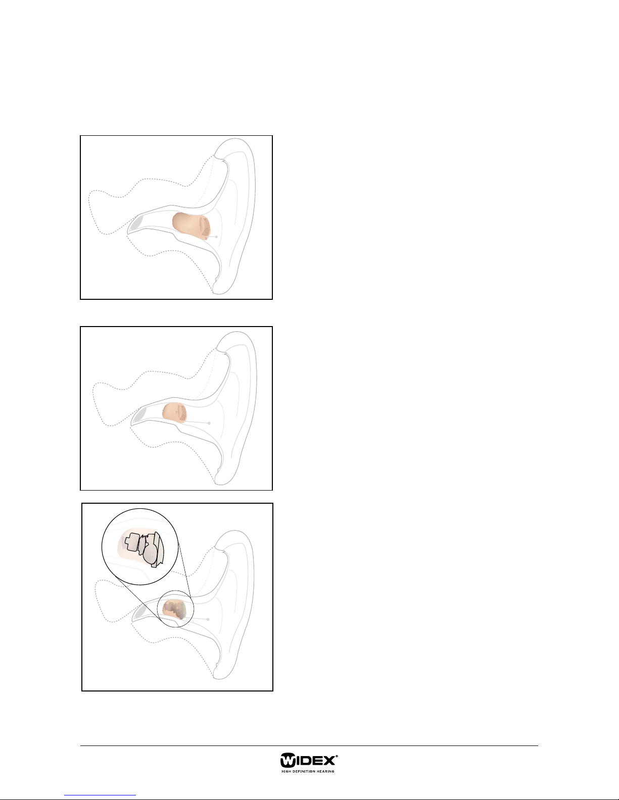
CIC
IIC
CIC vs IIC
The shell of the IIC houses the amplifier circuits, receiver
and battery drawer. These parts are placed in the locations shown, and the ear canal therefore needs to be wide
enough and long enough to accommodate an IIC hearing
aid.
Page 3
3/10
The process of impression-taking can be divided into three
major tasks:
• Inspection of the ear canal and eardrum
• Taking the impression
• Verifying the impression
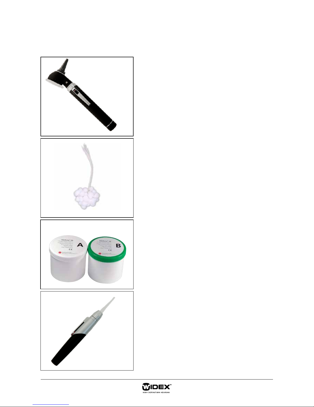
The following tools are required:
1. Otoscope
2. Otoblock material
3. Impression mass
4. A lightpen
Remember, you should always ensure good hygiene prior
to impression-taking.
1
2
3
4
requIred tools
Page 4

4/10
To make sure that the client is relaxed
during the impression-taking process, it is
important to explain the procedure. You
should:
• Find out whether the client has had
ear impressions taken before.
• Find out whether the client has ever
felt dizziness during impressiontaking.
• Explain the insertion of the otoblock
to protect the eardrum.
• Explain that the ear canal will be
filled with silicone during the hardening process.
• Explain the occlusion eect during
the impression-taking.
• Explain that due to the deep impression, some people may feel the urge
to cough.
takIng the ImpressIon
It is important to make an impression
that is long enough. A common guideline
states that the impression needs to make
it “just past the second bend”, but in cases
where the first and second bends are close
to each other, this is not enough.
You should therefore place the otoblock as
close to the eardrum as possible, to ensure
a suitable impression length.
Page 5

5/10
WidthThickness
Width
TR
Thickness
TR
TR
Length
Thickness
Width
Length
Inner end of HA
Inner end of HA
Transverse receiver
Outer end of HA
www.widex.pro\iicgauge
IIC gauge
The gauge is a guidance tool for hearing
care professionals, to help you determine
whether an IIC hearing aid might be an
option for a given client. Measurement is
a multiple-step process which requires an
impression of the client’s ear canal, the
Widex IIC gauge, and a marker pen. As the
ear canal is oval in shape, measurements
must be undertaken of both the width and
the thickness at dierent points.
Since there are two dierent receiver
designs to choose between, straight and
transverse, the gauge has a brown section
and an orange section, giving the minimum dimensions needed for each of these
solutions.
Please follow the steps below to complete
the verification process.
the verIfICatIon proCess
Page 6

6/10
1. Outer end verification I
First of all, you will need to measure the
minimum width required to place the outer
end of the IIC hearing aid, i.e. the part which
contains the battery drawer.
Hold or place the ear impression with the
canal part pointing upwards. Take the gauge
and place the cutout marked WIDTH in the
green section at the tip, i.e. the inner end of
the canal part, or the narrowest part of the
impression.
Slide it downwards until the impression width
blocks further movement. Mark this point
with a pen.
TR
TR
TR
Page 7

7/10
2. Outer end verification II
Next, turn the impression 90 degrees to
measure the thickness at the marked point.
If the impression does not slide into the cutout marked THICKNESS in the green section,
the marking on the impression will roughly
represent the outer end of the hearing aid.
If the impression slides into the cutout, slide
the gauge further downwards until the impression thickness blocks further movement.
Mark this point with a pen. This lower point
will then roughly represent the outer end of
the hearing aid.
TR
Page 8

8/10
3. Transverse receiver verification I
Next, you will need to check the minimum
width required to place the transverse receiver in the IIC hearing aid.
Hold or place the ear impression with the
canal part pointing upwards.
Place the cutout marked WIDTH TR in the
orange section at the tip of the impression.
Slide it downwards until the impression width
blocks further movement. Mark this point
with a pen.
TR
TR
TR
Page 9

9/10
4. Transverse receiver verification II
Turn the impression 90 degrees to measure
the thickness at the marked point. If the
impression does not slide into the cutout
marked THICKNESS TR in the orange section, the marking on the impression will
roughly represent the inner end of the hearing aid using a transverse receiver.
If the impression slides into the cutout, slide
the gauge further downwards until the impression thickness blocks further movement.
Mark this point with a pen. This lower point
will then roughly represent the inner end of
the hearing aid.
TR
Page 10

10/10
After completing the measurements of
width and thickness needed for a transverse
receiver, you can now measure the length
between the
markings.
Place the cutout marked LENGTH TR (orange section) alongside the canal part of the
impression to check whether the minimum
length has been met for the solution.
5. Length verification (transverse receiver)
6. Normal/Straight receiver verification
If the above verification process has shown that the ear canal is too narrow to fit an IIC with a transverse receiver,
you can alternatively check the minimum width needed to place a NORMAL/STRAIGHT receiver in the IIC hearing
aid. To do this you need to repeat the process described in step 3, step 4 and step 5 using the brown section of
the gauge.
 Loading...