

WideBand Professional Quick Installation Manual

WideBand Professional Series
Gigabit Ethernet Switches
___________________________
QUICK INSTALLATION GUIDE
___________________________
MANAGEMENT GUIDE
___________________________

2
TABLE OF CONTENTS
Quick Installation Guide ..................................................................................................................................... 4
Introduction ........................................................................................................................................................... 4
8- 16- and 28-port 10/100/1000 Switches ...................................................................................................... 4
8+8 10/100/1000 Managed Copper/Fiber Switch ........................................................................................... 4
24+4-port Un/Managed 10/100 Copper, plus 10/100/1000 Copper Switch ................................................... 4
24+2+2-port Un/Managed 10/100 Copper, plus 10/100/1000 Copper/Fiber Switch ...................................... 4
Installing the Switch .............................................................................................................................................. 5
Package Contents .......................................................................................................................................... 5
Description of Hardware ................................................................................................................................. 6
Mounting the Switch ....................................................................................................................................... 8
Stacking Switches on a Flat Surface .............................................................................................................. 8
Mounting Switches in a Rack ......................................................................................................................... 8
Connecting the Switch System ....................................................................................................................... 8
Making a Connection to an RJ-45 Port .......................................................................................................... 9
Installing a Fiber Module .............................................................................................................................. 10
Connecting Fiber Cable ................................................................................................................................ 10
Powering On the Switch ............................................................................................................................... 10
Verifying System and Port Status ................................................................................................................. 10
Verifying System Operation .......................................................................................................................... 10
Management Guide ........................................................................................................................................... 12
Switch Management ............................................................................................................................................ 12
Required Connections .................................................................................................................................. 12
Obtaining and Installing the Management Program ............................................................................................ 12
Accessing the Switch via a Network Connection ................................................................................................ 13
Network Management Security .................................................................................................................... 14
Accessing the Switch via the Serial Port ............................................................................................................. 15
Switch Summary & Menu .................................................................................................................................... 15
Switch Identification ............................................................................................................................................ 16
Restoring Factory Defaults ........................................................................................................................... 17
Clearing Security .......................................................................................................................................... 18
Updating Switch .................................................................................................................................................. 18
Update Firmware .......................................................................................................................................... 18
Management Upgrade .................................................................................................................................. 19
Rebooting Switch ......................................................................................................................................... 20
Advanced Subjects ........................................................................................................................................... 20
Port Information ................................................................................................................................................... 20
Current Status Bar ........................................................................................................................................ 21
Link Status Details ........................................................................................................................................ 22
Port Statistics ...................................................................................................................................................... 22
Clearing Statistics ......................................................................................................................................... 24
Port Mirroring ...................................................................................................................................................... 24
VLANs ............................................................................................................................................................... 25
VLAN Classification ...................................................................................................................................... 25
VLAN Rules and Indices .............................................................................................................................. 25
Making VLAN Assignments .......................................................................................................................... 27
VLAN Membership Table ............................................................................................................................. 28
MAC Address Tables .......................................................................................................................................... 30
Multicast Tables .................................................................................................................................................. 32
SNMP Management Control ............................................................................................................................... 33
Assigning an IP Address .............................................................................................................................. 34
Configuring SNMP Communities .................................................................................................................. 34
Loop Resolution .................................................................................................................................................. 35
Link Aggregation (Port Trunking) ........................................................................................................................ 37
Aggregation Status at a Glance ................................................................................................................... 39
Link Aggregation’s Effect on Other Management Features ......................................................................... 39
Configuring Aggregates Manually ................................................................................................................ 40

3
Hash Configurations ..................................................................................................................................... 40
Layer 3 Routing ................................................................................................................................................... 40
Assigning VLAN IP Addresses ..................................................................................................................... 41
Setting a Gateway For The Switch ............................................................................................................... 42
Managing Static Routes ............................................................................................................................... 42
Routing Example .......................................................................................................................................... 42
Management Configuration Templates ............................................................................................................... 43
Fiber Information ............................................................................................................................................... 46
Optional Fiber Modules ....................................................................................................................................... 46
1000BASE-SX Mini-GBIC ............................................................................................................................ 46
1000BASE-LX Mini-GBIC ............................................................................................................................. 46
Cable Types ........................................................................................................................................................ 47
Installing a Fiber Module ..................................................................................................................................... 47
Connecting a Mini-GBIC ..................................................................................................................................... 47
Power Requirements ........................................................................................................................................ 48
Contact Customer Service ............................................................................................................................... 49
Copyright © 2002-5 WideBand Corporation. All rights reserved. V02.21

4
WideBand Professional Series Gigabit Ethernet Switches
QUICK INSTALLATION GUIDE
Introduction
The WideBand Professional Series Gigabit Ethernet Switches are high performance switches
available in the following models:
8-port Un/Managed 10/100/1000 Switch
16-port Un/Managed 10/100/1000 Switch
28-port Un/Managed 10/100/1000 Switch
8+8-port Un/Managed 10/100/1000 Copper/Fiber Switch
24+4-port Un/Managed 10/100 Copper, plus 10/100/1000 Copper Switch
24+2+2-port Un/Managed 10/100 Copper, plus 10/100/1000 Copper/Fiber Switch
8- 16- and 28-port Un/Managed 10/100/1000 Switches
Available managed or unmanaged, these switches are ideal as network core, backbone or
server farm switches for today’s networks. Each port supports 10/100/1000BASE-T copper to
provide flexibility for an easy migration path to higher bandwidths as gigabit moves to the
desktop.
8+8 10/100/1000 Un/Managed Copper/Fiber Switch
This switch is a scalable 1000BASE-T / 1000BASE-X managed or unmanaged switch with 8
copper auto-negotiation ports and 8 Small Form Pluggable (SFP) mini-GBIC slots for
1000BASE-SX or 1000BASE-LX modules. The fiber modules can be added as needed.
Whether the application is aggregating eight fiber lines to a Gigabit core or just linking a copper
workgroup to a fiber backbone, the 8+8 Switch is a cost-effective way to achieve maximum
performance.
24+4-port Un/Managed 10/100 Copper, plus 10/100/1000 Copper Switch
This model makes a great, cost effective way to connect a large number of workstations to a
network backbone or high performance server. With 24 10/100BASE-T ports and 4
10/100/1000BASE-T ports, this switch is excellent for the client edges of your network.
24+2+2-port Un/Managed 10/100 Copper, plus 10/100/1000 Copper/Fiber Switch
This switch is the solution for those distant locations where a number of clients need a high
performance connection to the LAN. This model includes 24 10/100/BASE-T ports, plus 2
copper 10/100/1000BASE-T ports and 2 Small Form Pluggable (SFP) mini-GBIC slots. A
combination that makes this switch perfect for the outer reaches of a LAN.
Layer 2 Switching: The WideBand Professional Series Gigabit Ethernet Switches support
Layer 2 switching at wire speed, along with extensive support for VLANs, traffic prioritization,
and packet filtering based on Layer 2, 3, and 4 information.

5
Store-and-Forward Blocks Error Packets: Store-and-Forward switching technology blocks all
error packets within the Professional Series Gigabit Switch, preventing the generation of
unwanted (useless) network traffic.
Flow Control Enables High Throughput: The Professional Series Gigabit Ethernet Switches
support flow control (IEEE 802.3x for Full Duplex, Back Pressure for Half Duplex), which
prevents packet losses that result from mismatches between the sending and the receiving
speeds. The Switch achieves highly reliable and superior throughput while providing a truly
efficient network environment.
All Copper Ports Support Auto MDI/MDI-X: All copper ports support the Auto MDI/MDI-X
feature that automatically detects straight-through/crossover cable types. Since these ports
recognize both cable types, communication problems resulting from cable type mismatches are
eliminated. This new feature also eases cascading with other hubs and/or switches.
WGNA Certified: All copper ports of the Professional Series Gigabit Ethernet Switches meet
the WideBand Gigabit Networking Alliance’s stringent certification, assuring users that they can
be used to transmit data up to a full 100 meters with a bit error rate of less than 1 per million on
all grades of Category 5 cables.
Among other advanced features supported by the Professional Series Switches are the
following:
VLANs – Supports 4094 VLANs (IEEE 802.1Q) based on MAC, Port, Subnet, and
Protocol
Port Statistics – including counters defined by Ethernet SNMP MIB and RMON MIB
Port Mirroring – Incoming and outgoing traffic of any port can be mirrored.
Spanning Tree – IEEE 802.1D network loop resolution protocol
Trunking – IEEE 802.3ad link aggregation control protocol
SNMPv1 – Support for rfc1157, rfc1213, rfc1493 and rfc1643
L3 Routing – Up to 64 virtual router ports (only on L3 switches)
The WideBand Professional Series Gigabit Ethernet Switches provide optional management
software that allows you to configure or monitor the switch. To manage the switch, you can
access the Management Software via a local PC over the network or over the Serial Port on the
front panel of the switch.
Installing the Switch
Before installing the switch, verify that you have all the items listed under "Package Contents." If
any of the items are missing or damaged, contact your local distributor. Also be sure you have
all the necessary tools and cabling before installing the switch. Note that this switch can be
installed on any suitably large, flat surface or in a standard EIA 19-inch rack. After installing the
switch, refer to the Management Guide portion of this Manual to set up its more advanced
features, such as VLANs and Spanning Tree.
Package Contents
The WideBand Professional Series Switch package includes the following items:
6
Professional Series Switch
8-port Gigabit Switch
16-port Gigabit Switch
Management software CD (only managed switches)
AC power cord
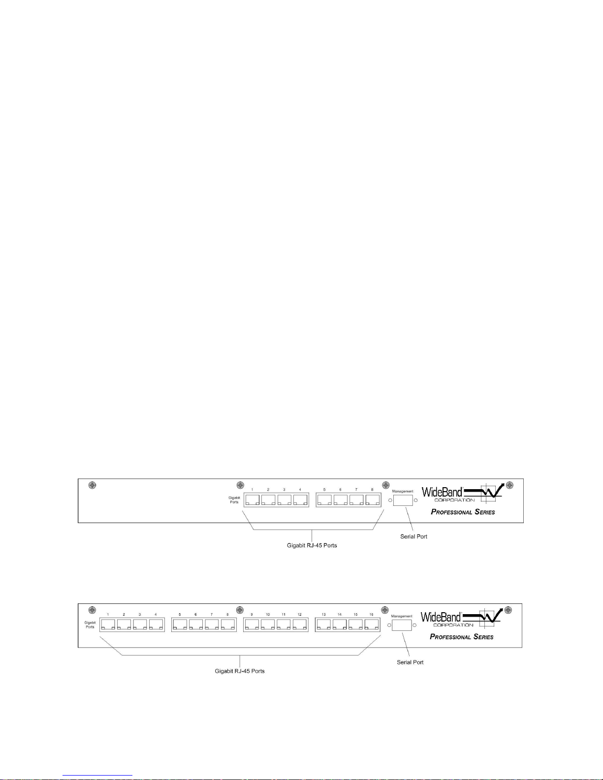
Description of Hardware
The Professional Series Switches come in six port configurations:
8-port Un/Managed 10/100/1000 Switch
16-port Un/Managed 10/100/1000 Switch
28-port Un/Managed 10/100/1000 Switch
8+8-port Un/Managed 10/100/1000 Copper/Fiber Switch
24+4-port Un/Managed 10/100 Copper, plus 10/100/1000 Copper Switch
24+2+2-port Un/Managed 10/100 Copper, plus 10/100/1000 Copper/Fiber Switch
All RJ-45 ports on these units operate at 10, or 100 Mbps and support auto-negotiation of
speed, duplex mode (i.e., half or full duplex), and flow control, while gigabit ports also support
1000 Mbps. Note that when using the auto-negotiation feature, speed, transmission mode, or
flow control can be automatically set as long as this feature is also supported by the attached
device. Otherwise, these items can be manually configured for any connection.
All fiber ports are Small Form Pluggable (SFP) mini-GBIC slots for 1000BASE-SX or
1000BASE-LX modules, providing as much as 10km transmission distance, depending on
which module you choose.
The base unit also includes LED indicators for start-up, loading, and port indications that
simplify installation and network troubleshooting.
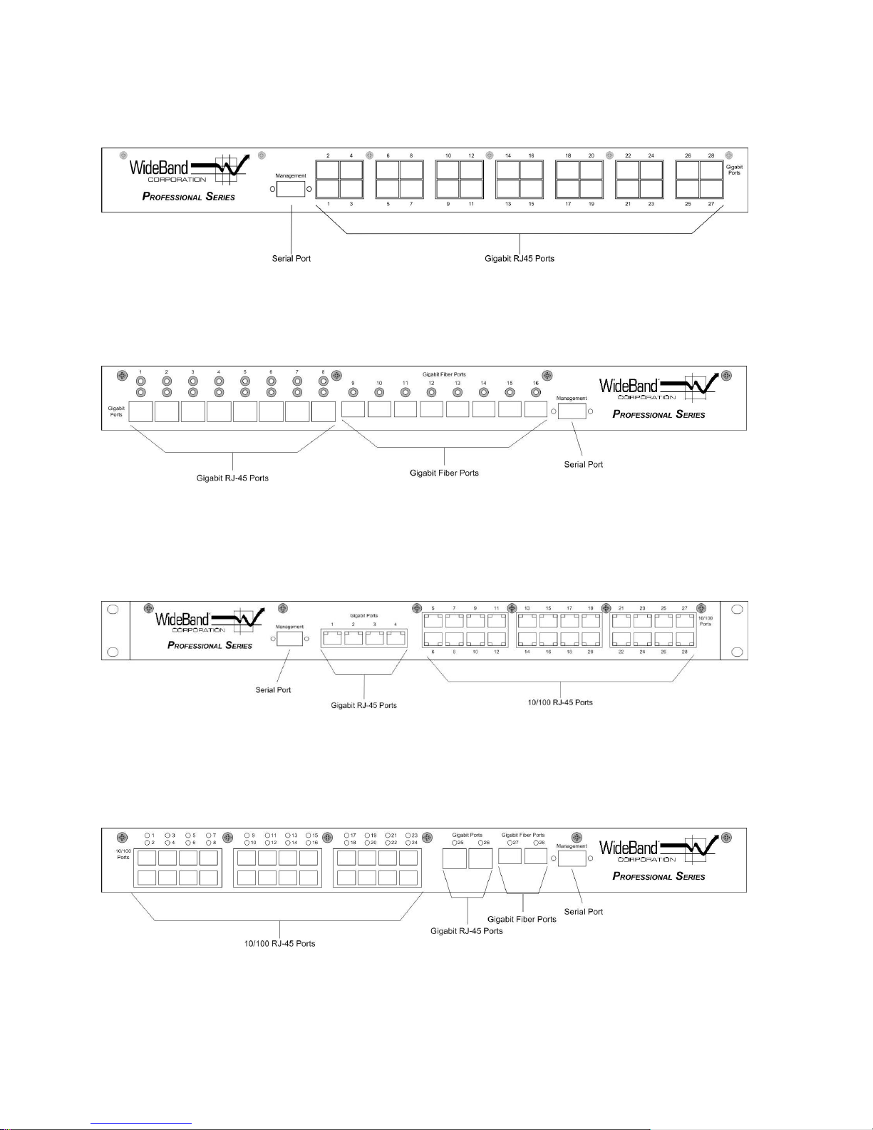
7
28-port Gigabit Switch
8+8 Gigabit Switch
24+4 10/100 Switch with Gigabit Connections
24+2+2 10/100 Switch with Gigabit Connections

8
Mounting the Switch
This switch can be placed directly on your desktop, or mounted in a rack.
Before you start installing the switch, make sure you can provide the right operating
environment, including power requirements, sufficient physical space, and proximity to other
network devices that are to be connected. Verify the following installation requirements:
Power requirements: 100 to 220 VAC (plus or minus 10%) at 50 to 60 Hz (plus or minus
3 Hz). If there is a voltage control switch located on the rear panel next to the power cord
connector, this switch must be set to the correct voltage setting.
The switch should be located in a cool, dry place, with at least 10 cm (4 in.) of space on
the sides for ventilation.
Place the switch out of direct sunlight and away from heat sources or areas with a high
amount of electromagnetic interference.
If you intend to mount the switch in a rack, make sure you have all the necessary
mounting screws, bolts and nuts, and the right tools.
Make sure that network cables and connectors needed for installation are available.
Stacking Switches on a Flat Surface
The Professional Series Switch can be placed anywhere there is enough flat space, such as on
a table or desktop. The first switch should be placed on a firm, flat surface where you want to
install the stack, and subsequent switches may be stacked carefully, one on top of another.
Mounting Switches in a Rack
Please comply with the following instructions to ensure that your switch is securely mounted in
the rack:
1. Use a standard EIA 19-inch rack.
2. Use the brackets that are already attached to the switch.
3. Position the switch in the rack by lining up the holes in the brackets with the appropriate
holes on the rack, and then use appropriate rack-mount screws to mount the switch in
the rack.
Connecting the Switch System
The Professional Series Switches provide a number of different port configurations. Each RJ-45
port supports connection to 10 Mbps Ethernet and 100 Mbps Fast Ethernet, and has the ability
to run in full or half-duplex operation. While gigabit ports also support 1 Gbps Gigabit Ethernet
(GbE). The switch automatically sets the transmission speed for each port to use the highest
speed supported.
The transmission mode can be set for each port using auto-negotiation (if also supported by the
attached device). However, if the device attached to any port on the switch does not support
auto-negotiation, you can manually configure the transmission mode via the optional
management software, accessible from a local PC.

9
Making a Connection to an RJ-45 Port
You can use straight-through or crossed twisted-pair cable to connect any RJ-45 port on the
switch to any device that uses a standard network interface such as a workstation or server, or
to a network interconnection device such as a bridge or router (depending on the port type
implemented).
1. Prepare the network devices you wish to network. Make sure you have installed
10BASE-T, 100BASE-TX, or 1000BASE-T network interface cards for connecting to the
switch's RJ-45 station ports.
2. Prepare straight-through or crossed unshielded twisted-pair cables with RJ-45 plugs at
both ends. Use 100-ohm Category 3 or greater cable for standard 10 Mbps Ethernet
connections, or 100-ohm Category 5 cable for 100 Mbps Fast Ethernet or 1000 Mbps
GbE connections.
3. Connect one end of the cable to the RJ-45 port on the network interface card, and the
other end to any available RJ-45 port on the switch. When inserting an RJ-45 plug, be
sure the tab on the plug clicks into position to ensure that it is properly seated.
Caution: Do not plug a phone jack connector into any RJ-45 port. This may damage the switch.
Instead, use only twisted-pair cables with RJ-45 connectors that conform to FCC standards.
Notes:
1. The transmission mode for each of the copper ports on each Professional Series
Switch is automatically set as Auto-MDI/MDI-X support. So, the Switch is
designed to connect with other devices through any of its copper ports. When
connecting to another compatible adapter, whether or not straight-through cable
is utilized, the Switch will automatically, electronically ensure that a straightthrough connection is made. Similarly, when connecting to another compatible
switch or hub, the Switch will automatically, electronically ensure that a crossover
connection is made.
2. All copper ports on WideBand’s Professional Series Switches are WGNA
Certified to transmit data up to a full 100 meters (328 ft.) with a bit error rate of
less than 1 per million on all grades of Category 5 cables.
3. We advise using Category 5 cable for all network connections to avoid any
confusion or inconvenience in the future when you upgrade attached devices to
Fast Ethernet or GbE.
Restrictions on Cascade Length -- The IEEE 802.3 standard recommends restricting the
number of hubs (i.e. repeaters) cascaded via twisted-pair cable to four, while IEEE 802.3u
provides even stricter recommendations for Fast Ethernet. Therefore, when cascading devices
other than this switch, please refer to the equipment’s accompanying documentation for
cascade restrictions. However, please note that because switches break up the path for
connected devices into separate collision domains, you need not include the WideBand
Professional Series switch or connected cabling in your calculations for cascade length
involving other devices.

10
Installing a Fiber Module
LED Over Each Port
On Green
Port has a valid 10/100 Mbps connection, port enabled.
On Blue
Port has a valid 1 Gbps connection, port enabled.
On Red
Port has detected a physical error on the connected wire.
Off
Port either has no valid connection or has been disabled.
To Install a Fiber Module, simply push the Module into the port until you feel it lock into place. It
is immediately ready to accept a fiber cable terminated with a mini-GBIC connector. To remove
the Module, lift up on the small bar that protrudes from the top of the Module, and pull it out.
Connecting Fiber Cable
Similarly, the mini-GBIC connector on the fiber cable snaps into place in the Fiber Module.
Release its tab to remove the cable.
Powering On the Switch
1. If there is a voltage control switch located on the rear panel next to the power
cord connector, this switch must be set to the correct voltage setting.
2. Plug the power cord into the power socket on the rear of the switch, and the other end
into a power outlet.
3. As the switch powers up, the LEDs near the copper ports will come on in blue. This
indicates that the switch is running start-up tests. Once these tests have successfully
completed, the lights will change to green, indicating that the switch is loading programs.
When the loading is completed, the lights will go off, and then, when a cable is plugged
into one of the copper ports, the light above it will come on -- green lights indicating
10/100 Mbps and blue lights indicating 1 Gbps.
Verifying System and Port Status
The LEDs located on the front panel are described in this section.
Check each connection by viewing the port indicators shown in the following table:
Verifying System Operation
Copper Ports -- Verify that all attached devices have a valid connection. The switch monitors
the link status for each port. When any device is properly connected to the switch via a copper
port and is transmitting a link signal, the Link Indicator (the LED above the port) will light up for
the corresponding port. If the port has a valid link but is detecting errors, a red light will come on
above the port. If the Link Indicator fails to light, or a red light appears when you connect a
device to a copper port, check the following items:
Be sure network cables and connectors are properly attached to the connected device
Be sure your cable is functioning properly by using it for another port and attached
and the switch.
device that displays valid indications when connected to the network.

11
Be sure no twisted-pair cable exceeds 100 meters (328 feet). Access Switch
Module
Cable
Maximum Length
WB1MGBICPRO-LX
9/125 µm single-mode
Up to 10Km
WB1MGBICPRO-SX
62.5/125 µm multimode
300m / 984 ft
50/125µm multimode
860m / 2821 ft
WBMFPLCSCPRO
LC-to-SC Multi-Mode Fiber Patch Cable
2m
WBMFPLCSTPRO
LC-to-ST Multi-Mode Fiber Patch Cable
2m
WBSFPLCSCPRO
LC-to-SC Single-Mode Fiber Patch Cable
2m
WBSFPLCSTPRO
LC-to-ST Single-Mode Fiber Patch Cable
2m
Management to make sure the port is enabled.
Fiber Ports – Verify that all attached devices have a valid connection. Check the Link Indicator
above the port. On a managed switch, access the Port Information screen of the WideBand
Network Management System to verify the link status of fiber ports. On unmanaged switches,
verify valid connections by running a “ping” test (in DOS type “ping TCP/IP ADDRESS” where
TCP/IP ADDRESS is the TCP/IP address of another computer that is also connected to the
switch. Hit “Enter” and wait a few moments. You should receive four lines of “Reply from
TCP/IP ADDRESS”).
The maximum length for Gigabit connections should be within the limits listed in the
following table:

12
MANAGEMENT GUIDE
Switch Management
The WideBand Network Management Software is available for advanced management
capability. This software permits the user to manage WideBand Professional Series Switches
from a PC on which the management software is installed either via the network connection or
through the serial port located on the front panel of the switch. The software supports
management functions such as the following:
Find and list all WideBand Switches on the network
Update Switch Firmware
Upgrade an Unmanaged Switch to a Managed Switch
Assign names and descriptions to switches
Configure port information
Display port statistics
Setup port mirroring
Set up and manage VLANs
View MAC address forwarding databases
Configure multicast tables
Manage SNMP settings
Configure loop resolution settings
Manage link aggregation (port trunking)
Manage L3 routing settings on layer 3 switches
Save, load, or delete management templates
Only one copy of the Management Software is required to manage all of the WideBand
Professional Series Managed Switches on your L2 network.
Required Connections
The WideBand Network Management Software can be run from any PC where the Program
is installed, either via a normal Local Area Network connection or via the Serial port on the front
panel of the switch.
Using the network connection, the PC need not be connected directly to the switch you wish
to manage. The management software will find all of the WideBand Professional Series
Switches on the VLAN it is connected to, and from it you will be able to manage any of these
Switches that has Management capability.
Using the Serial Port connection, only the Switch to which the PC is connected can be
managed.
Obtaining and Installing the Management Program
The WideBand Network Management Software is available for download any time, free of
charge. Switches that are purchased “unmanaged” may be upgraded using a unique
Management Token that must be installed, using the Management software, on each Switch.
Both Management Software and Token(s) may be obtained via the web at
http://www.wband.com/proswitch, or through your WideBand Reseller. To locate the WideBand
Authorized Resellers nearest you, contact the WideBand Sales Office at (888) 663-3050.
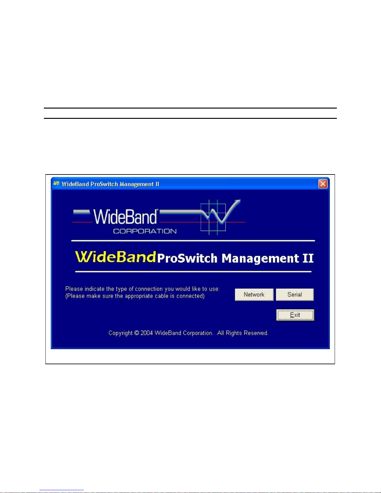
13
Figure 1 – Select what management interface you plan to use on the WideBand Management Software Startup
screen.
The Token(s) will be emailed to you within approximately 24 hours after being ordered.
To install the Management Software, download it from the WideBand Web Page and save
the software installation file on the PC where you want to install the Management System.
When you are ready to install it, find the file in Windows Explorer or My Computer and doubleclick on the name of the file. The installation process will begin. Follow the instructions you
receive on screen. When the program installation has completed, you can open the program by
clicking its icon on your desktop or in the Program Menu.
Accessing the Switch Via the Network Management System
When you open the Management Program, the startup screen will appear and you will need
to select which type of management interface you would like to use in this session. Because the
WideBand Professional Series Switches use the WideBand Management Protocol there is no
need to set up any configuration or addresses over the serial port before connecting. Therefore,
you may continue with network management by selecting the Network button.

14
The next screen you will see is the Switch Lists screen, shown in Figure 2 (above). As the
screen loads, the program will search the network to find all of the WideBand Professional
Series Switches on the connected VLAN. Until you have configured the switch identification
information, the switches can only be found using their Serial Numbers and Model Descriptions.
Once the switch information is configured, switches can be found and sorted in the following
categories:
Switch Name
Switch Description
Switch Serial Number
Switch Model Description
The switch list can be refreshed at any time by clicking on the Reload button.
You can manage any switch that appears in the list by simply clicking on it.
Network Management Security
If the switch you select is not password protected you will be prompted to enter a password
at this time. If you do not wish to enter a password press the Continue button. WideBand
Corporation strongly recommends that you password protect all of the switches on your network
for security reasons. Even unmanaged switches can have a password since they can be
upgraded to manageable switches.

15
If you selected a switch that is already password protected, you will be required to enter the
Menu
Description
Switch Name
The Name assigned to the Switch
Switch Description
Greater detail for identifying the Switch
Switch Department
The Department in which the Switch resides
Management Enabled
Indicates whether the Switch’s management features are enabled
Management Template
Lists the Management Template currently in use by the Switch
Switch Serial Number
The Switch’s Serial Number (same as the Switch’s MAC ID)
Model Number
The Switch’s Model Number
Firmware Version
Lists the Hardware/Firmware version the Switch is currently using
Model Description
A full description of the Switch’s Model Number
Switch Location
The physical location of the switch
Link
Description
Port Information
View and configure the current speed, duplex, and flow control settings of
each port
Port Statistics
Monitor the current statistic counter values for each port
VLANs
Set up and configure VLANs for every port
Switch ID
Assign identification information to the switch
Firmware
Update
Update the switch firmware or management status
Templates
Create and use Management Templates for ease of changing or
duplicating some management settings.
Find Switch
Go back to the “Switch Lists” screen to manage another switch
correct password before continuing to the Switch Summary & Menu screen.
The password can be cleared at any time on the Switch ID screen. A password is not
required for management over a serial port.
Accessing the Switch via the Serial Port
First, make sure that the switch is connected to your PC via a null modem RS-232 cable.
Then start the management program and click on the “Serial” button shown in Figure 1.
The software will automatically search the COM ports on the PC. If a valid connection to a
Professional Series switch is found it will be displayed in the switch list. Simply select the switch
to begin management.
Switch Summary & Menu
Once you have successfully selected a switch and entered a correct password the Switch
Summary & Menu screen (displayed in Figure 3) will open.
Most of the information on this screen can be set on the Switch Identification screen,
accessible using the Switch ID button at the bottom of this screen. Information is displayed on
this screen for both Managed and Unmanaged Switches, and is useful for “at-a-glance,” detailed
surveys of switch parameters. The information displayed on this screen is outlined in the
following table:
This screen also provides a “gateway” to managing the switch, allowing access to the
management functions, as described in the following table:
 Loading...