

Page 1

Widearea Telecommunication Technology Co., Ltd
Chengdu, Sichuan, China
Tel: +8628-84207501 Fax: +8628-84209696
Web Site: http://www.widearea.com.cn
ADSL Loop Extender and
ADSL Loop Extender Power Supply
AER800-8P & AEC-B1PH
Installation Manual
Version:5.0
Please read this
document carefully
before installation!
Page 2

ADSL Loop Extender Installation Manual Page 1
This publication may not be reproduced in whole or in part without the express written permission of Widearea.
Tel:+8628-84207501 +8628-84207506
Preface
This manual provides information on how to use this product. To make the best
use of this product, read this manual thoroughly before use. Please keep this
manual handy for ease of reference.
The contents of this document may be changed in the future, without prior
notice.
This booklet was created with thorough attention to the content. If,
however, you have a question, spot an error, or find a description lacking,
please refer to the end of this booklet for information on how to contact us.
All brand names and trademarks are the property of their respective
owners.
Page 3

ADSL Loop Extender Installation Manual Page 2
This publication may not be reproduced in whole or in part without the express written permission of Widearea.
Tel:+8628-84207501 +8628-84207506
Contents
1. Unpack ................................................................................................... 3
2.Technical Features ................................................................................... 3
3.Installation Environment ......................................................................... 4
4.Installation Steps ..................................................................................... 6
5.Troubleshooting ....................................................................................... 9
6.Techical Assistance & Customer Service Error! Bookmark not defined.
Abbreviations
CO Center Office
CPE Customer Point Equipment
DSLAM Digital subscriber line access multiplexer
Page 4
ADSL Loop Extender Installation Manual Page 3
This publication may not be reproduced in whole or in part without the express written permission of Widearea.
Tel:+8628-84207501 +8628-84207506
1. Unpack
Unpack equipment carefully; check for completeness against the purchase order. Notify
supplier if items are missing.
Note: Save packing material. All equipment returned must be packed in the original
packing material.
Inspect equipment for shipping damage, including bent or loose hardware, and broken
connectors.
If equipment was damaged in transit, contact supplier.
Product list
AER800-8P V5.0, one
Ф6mm×30mm nut, two
Hexagonal wrench, one
Installation manual, one
Note: AER800-8P V5.0 is configured with two AEC-B1PH, or one AEC-C2P V5.0. The
type of Power Supply is your choice when you order the product.
2.Technical Features
Table 1 Technical Specifications of AER800-8P V5.0
Size
280 mm×300 mm×100mm
Input Voltage
Powered by Power Supply of ADSL Loop Extender
Power Consumption
5W
Operating Environment
Temperature
-35℃~+50℃
Relative Humidity
5%~95% (Non-condensing)
Number of supported users
8 ADSL subscriber
Table 2 Technical Specifications of AEC-B1PH and AEC-C2PV5.0
Operating Environment
Temperature
-35℃~+50℃
Relative Humidity
5%~95% (Non-condensing)
Input Voltage
AC 110V or AC220V
or DC48V
Page 5
ADSL Loop Extender Installation Manual Page 4
This publication may not be reproduced in whole or in part without the express written permission of Widearea.
Tel:+8628-84207501 +8628-84207506
Output Voltage
DC 155V per port
Output Current
Less than 50mA
Fuse Rating
AEC-B1PH
0.5A
AEC-RACK(AEC-C2P)
10A
3.Installation Environment
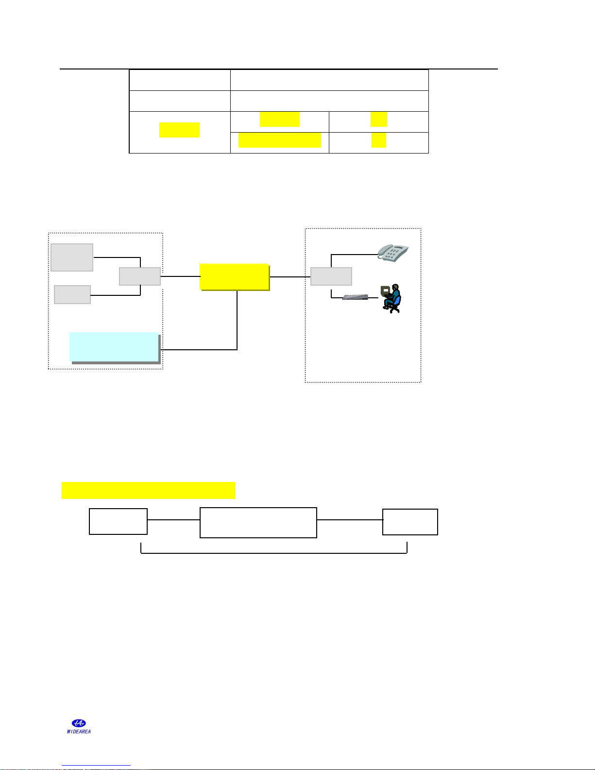
1) the actual lines connecting of equipment
Figure 1 actual lines connecting
L1: The signal twist pair connecting ADSL Loop Extender to DSLAM.
L2: The signal twist pair connecting ADSL Loop Extender to Modem.
L3: The power twist pair connecting ADSL Loop Extender to power supply.
2) Ensure the upstream/downstream rate is no less than 128kbps/512kbps.
3) Resistance and distance demand
Figure 2 lines connecting sketch map
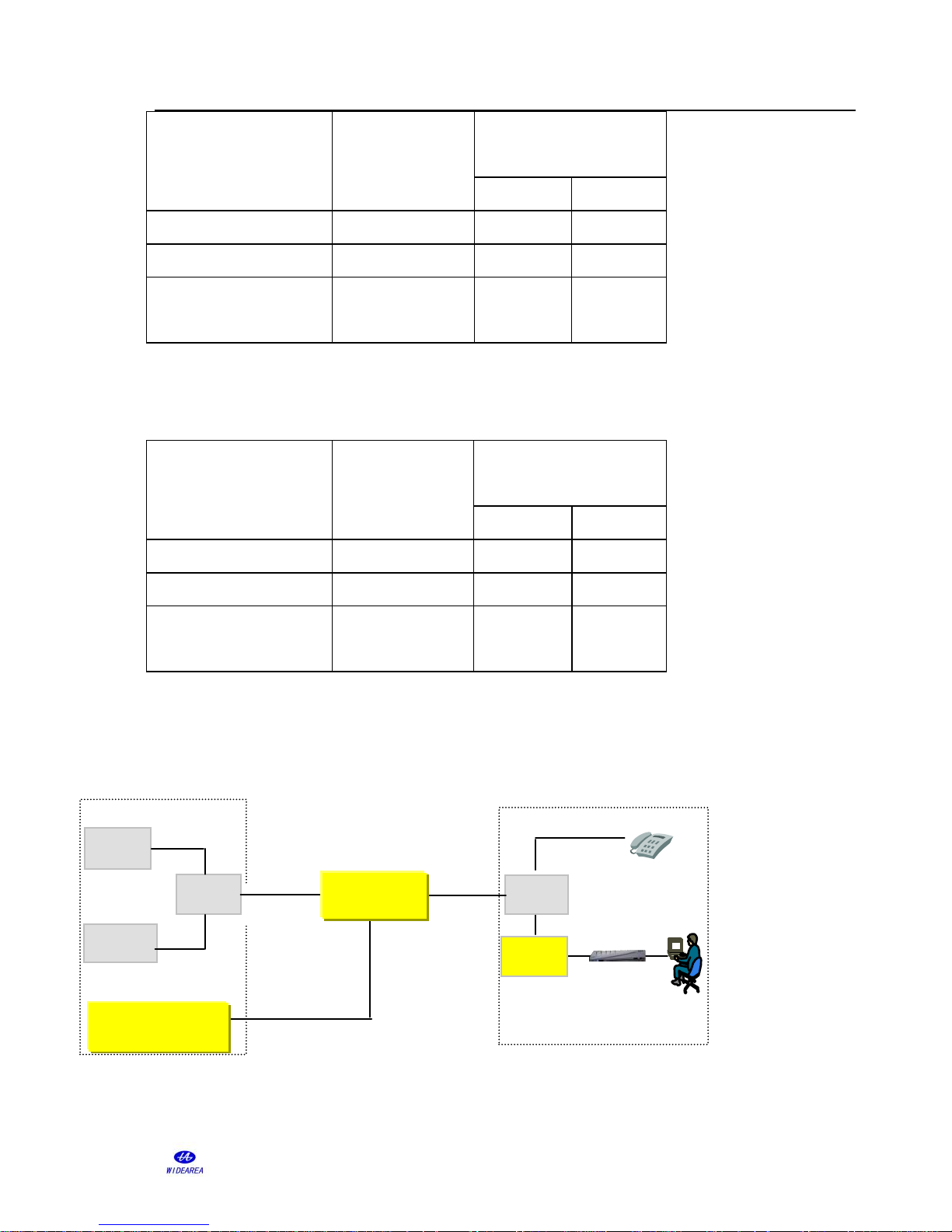
The recommended installation conditions are as follows.
① 26 AWG twist pair
The demand about resistance and distance is as follows:
Modem
CPE
L2
ADSL+PO
L
Power supply
L1
ADSL Loop Extender
Power Supply
DSL
switch
splitter
POT
CO
ADSL
Loop Extender
splitter
CO
CPE
ADSL Loop Extender
L
Page 6
ADSL Loop Extender Installation Manual Page 5
This publication may not be reproduced in whole or in part without the express written permission of Widearea.
Tel:+8628-84207501 +8628-84207506
Route
Loop resistance
demand Ohms
(Min.-Max.)
distance demand
(Min.-Max.)
kfeet
km
L1(CO-Extender)
450-1260
5.0-13.0
1.5-4.0
L2(Extender-CPE)
200-900
2.0-9.5
0.5-3.0
L(CO-Extender-CP
E)
800-2100
6.5-22.5
2.0-7.0
② 24 AWG twist pair
The demand about resistance and distance is as follows:
Route
Loop resistance
demand Ohms
(Min.-Max.)
distance demand
(Min.-Max.)
kfeet
km
L1(CO-Extender)
270-1050
5.0-20.0
1.5-6.0
L2(Extender-CPE)
170-1050
3.0-20.0
0.9-6.0
L(CO-Extender-CP
E)
550-1550
10.0-29.0
3.0-8.5
If the loop resistance between Extender and Modem is lower than the demand value, the
LA800 which you could choose and buy from our company can be added to increase loop
resistance. The option LA800 is to be installed between splitter and Modem when used on a
line with analog voice. Here is the application of LA800 below:
Figure 3 the application of LA800
Modem
copper line
ADSL+POTS
ADSL
copper line
power supply
copper line
ADSL+POTS
DSLAM
switch
splitter
splitter
POTS
ADSL
Loop Extender
ADSL Loop Extender
Power Supply
POTS
LA800
Page 7
ADSL Loop Extender Installation Manual Page 6
This publication may not be reproduced in whole or in part without the express written permission of Widearea.
Tel:+8628-84207501 +8628-84207506
4.Installation Steps
The AER800-8P is deployed with 2 AEC-B1PH or AEC-C2P V5.0 plugged into
AEC-RACK.
Note: The type of Power Supply is your choice when you order the product. The
installation of AEC-C2P follow the manual of AEC-C2P.
Commonly, the ADSL Loop Extender is installed in the junction cabinet, or one the wire
rope, or on the pole at the middle locality. The Power Supply can be installed either at CO or
at CPE with remote supply. The details about ADSL Loop Extender and Power Supply
installation are as follows:
4.1 Install the Power Supply(AEC-B1PH) for ADSL Loop Extender
1) the actual lines connecting of equipment
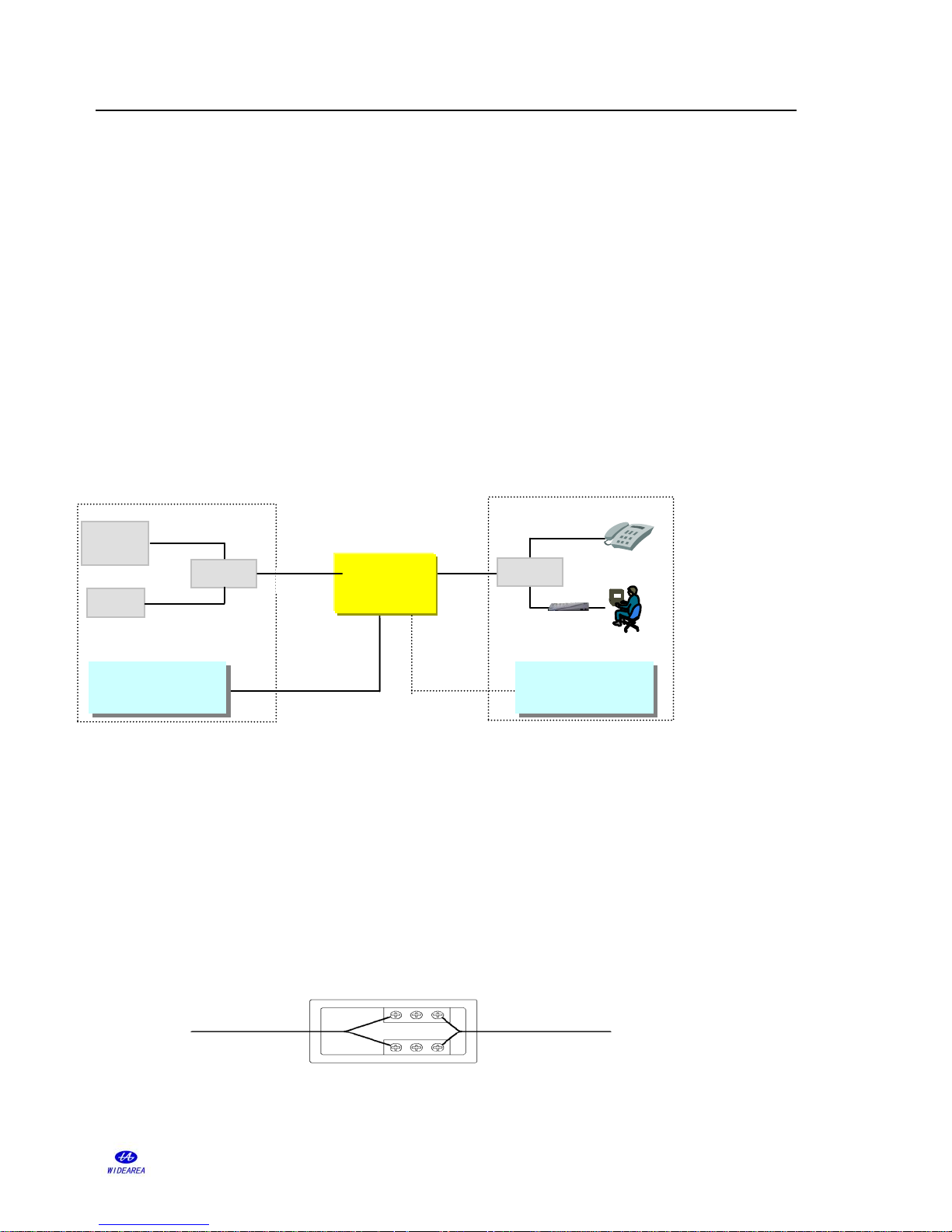
Figure 4 A or B way of ADSL Loop Extender with remote power supply
Generally , the Power Supply can be installed either at CO or at CPE with remote supply,
just as the Fig5. In the way of A or B, AC110V,AC220V or DC48V can be selected, make
sure the type of Power Supply you ordered. Two Spare copper pairs are needed for deliver
the output voltage to ADSL Loop Extender.
2)Connect tails
DC155V Output Cable
Power Supply Cable which needs to be connected
Figure.5 AEC-B1PH Connector Wiring Diagram
L
Modem
B CPE
L2
ADSL+PO
L
Power Supply
L1
ADSL Loop Extender
Power Supply
DSL
switch
splitter
POT
A CO
ADSL
Loop Extender
splitter
ADSL Loop Extender
Power Supply
Power Supply
Page 8

ADSL Loop Extender Installation Manual Page 7
This publication may not be reproduced in whole or in part without the express written permission of Widearea.
Tel:+8628-84207501 +8628-84207506
Three-core power cord without plug: used for DC48V power input, no polarity.
Three-core power cord with plug: used for AC110-240V power input.
Power output: 155V power output cable which is already connected to the terminal in wiring
box by factory.
Protection ground: Black protection ground wire should be connected to the protection
ground terminals.
○
1
Connect the power supply tail(L3)
There is an additional copper pair which power the ADSL Loop Extender. Now, the supply
voltage from wiring box will go through an additional copper pair and into the ADSL Loop
Extender directly. The detail way is as follows:
The Power Supply is installed in the cabinet, and the power supply cable connect with a
separate copper twist pair, at the placement of ADSL Loop Extender, the ADSL Loop
Extender’ blue/white lines connect with the same copper wire pair. For one thing, the cable
pair must be free of DC type faults. All shorts, grounds, cross, battery-crosses, and open
cable pairs must be identified and repaired.
② Ground
Connect the Power Supply equipment’s ground to CO’s grounding terminal directly.
③ Connect power cord
The supplied accessories include power cord for AC 110V、 AC220V or DC 48V. Connect
it to the AC 110V、AC220V or DC 48V power source with good connection. To easy the
installation, DC power source connection is no polarized.
After power supply is connected, the power indicator should be solid on. Flashing indicator
indicates short circuits or over-current alarm condition.
Attention: ADSL Loop Extender’s Power Supply should NOT be turned on until the
Page 9
ADSL Loop Extender Installation Manual Page 8
This publication may not be reproduced in whole or in part without the express written permission of Widearea.
Tel:+8628-84207501 +8628-84207506
Extender installation is finished.
4.2 Install the ADSL Loop Extender
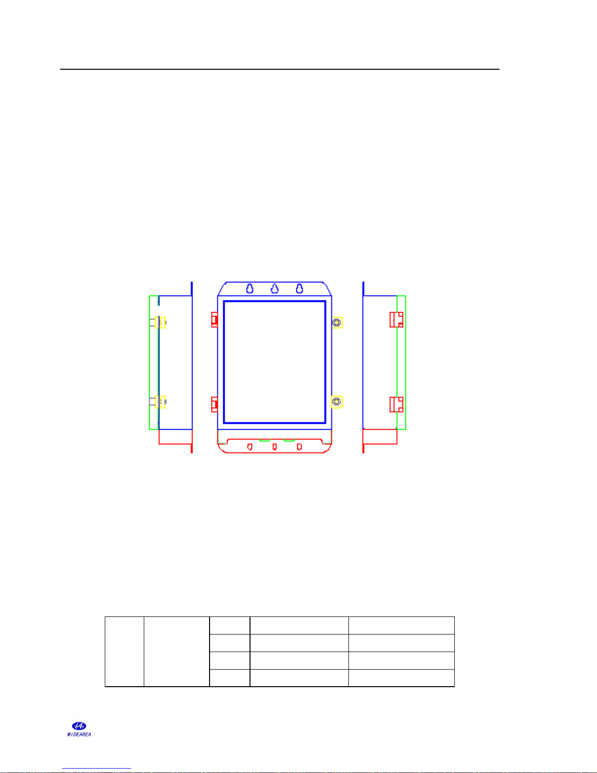
① ADSL Loop Extender can be placed in the junction cabinet if there is inner room
available. Or ADSL Loop Extender can be mounted in the box through supplied mounting
brackets.
Attention: Copper-core wire with no less than 1.5mm2 section area is required as
ground wire. One end of the wire should connect to Loop Extender’s ground terminal.
The other end of the wire should connect to a good grounding point.
Figure 6 AER800-8P installing Outdoors
② Connect the cable
Unlock the box of AER800-8P with the hexagonal wrench. Wiring sockets on front panel for
DSLAM and Modem side signal wiring and power supply wiring. Metal bolt on front panel
for ground connection. The detailed connection follows the picture on silk-screen.
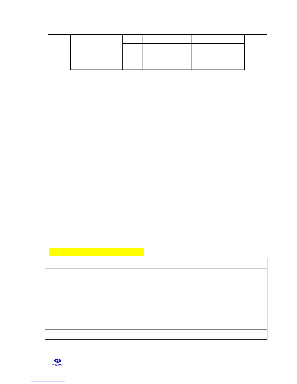
Table 4 - Twist-wires Connection Description of AER800-8P
First
part
PWR1(A/B)
11
CO11(A/B)
CPE11(A/B)
12
CO12(A/B)
CPE12(A/B)
21
CO21(A/B)
CPE21(A/B)
22
CO22(A/B)
CPE22(A/B)
Page 10
ADSL Loop Extender Installation Manual Page 9
This publication may not be reproduced in whole or in part without the express written permission of Widearea.
Tel:+8628-84207501 +8628-84207506
Second
part
PWR2(A/B)
31
CO31(A/B)
CPE31(A/B)
32
CO32(A/B)
CPE32(A/B)
41
CO41(A/B)
CPE41(A/B)
42
CO42(A/B)
CPE42(A/B)
After power on, the “STATUS” LED should be lightened in a few seconds and remain on
during normal system operation. Lock the box with the hexagonal wrench, pay attention to
wrench clockwise rotation to undersurface of the box into parallel lines, then stop rotation.
③ Power up
After confirming that all the twist-pair cables are connected correctly and enclosure is
securely installed, power up the system. The ADSL Loop Extender will work in 20 seconds
after power is supplied stead.
Attention:
a) “A” and “B” represent A and B wire of the twist-pair. No polarity.
b) Before power up the system, please make sure all the connections are correct.
c) When the power supply wire is active, do NOT operate the A and B wire of the
supply pair simultaneously. The A wire and B wire should be isolated.
5.Troubleshooting
If the ADSL Loop Extender can’t work well, please follow the Table5 and Table6 to
find out the problems.
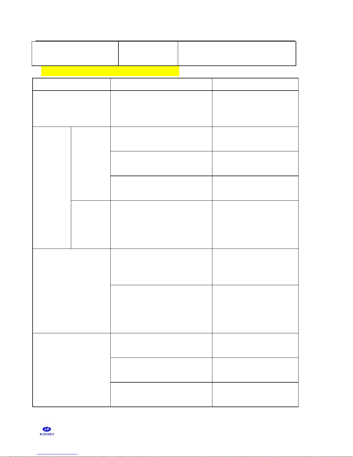
Table 5 - AEC-B1PH Troubleshooting
Problem Description
Possible Reason
Suggested Resolution
Equipment does not work after
power-up. Status LED is OFF.
Power supply cable is
not correctly
connected.
Check power supply cable connection.
Power indicator flashes.
Power output
circuitry fails.
Check whether the connection is shorted. Or
check whether the connection between
Extender and Modem is OK.
Output is OK but the Extender
Power output cable
Correct the power output connection or check
Page 11
ADSL Loop Extender Installation Manual Page 10
This publication may not be reproduced in whole or in part without the express written permission of Widearea.
Tel:+8628-84207501 +8628-84207506
does not work.
connection is error or
short.
cable. Or check whether the distance between
DSLAM, Extender, Modem is proper.
Table 6 - ADSL Loop Extender Troubleshooting
Problem Description
Possible Reason
Suggested Resolution
Extender does not work after
power-up. Status LED is
OFF.
Power supply cable is not connected
properly.
Check power supply and power
cable.
No
connection
Status LED
is always on.
Cables at DSLAM side or Modem side
are not connected properly.
Correct the cable connection.
Line quality is worse between CO and
CPE side.
Change good quality cable.
There is telephone before the splitter on
CPE side.
Discard the telephone before the
splitter on CPE side.
Status LED
flashes.
Cables linked ADSL Loop Extender are
not connected properly.
Correct the cable connection. Or
check whether the distance
between DSLAM, Extender,
Modem is proper.
There is noise in user’s
telephone
Cable is connected to ground or the
insulation is not good caused by men
during the construction process.
Check the cables.
Cable is too near to some electric
equipments with strong magnetic field,
such as high power sounder, selenium
rectifier and high power motor.
Make cable far from the strong
magnetic field.
Internet is slow, frequent
off-line problem
Affection of computer hardware
failures, system failures and virus.
Check computer or take with PC,
testers and so on to deal with.
The parallel cable at CPE side is too
long or the connector is oxidation.
It is better to change the parallel
cable to copper twist cable.
The cable to CPE side is connected with
too many connectors.
Avoid exposed connectors, use
good quality cable instead
Page 12

ADSL Loop Extender Installation Manual Page 11
This publication may not be reproduced in whole or in part without the express written permission of Widearea.
Tel:+8628-84207501 +8628-84207506
scattered connectors.
 Loading...