

Wide IDP2130HB, IDP2130TS User Manual
Issued Date
Revision Status
Title
Page No.
1 / 45
V2.3
2009-04-07
IDP2130HB / IDP2130TS
(AL21NUX)
USER’S MANUAL
IDP2130HB
IDP2130TS
1600 x 1200 TFT LCD MONITOR
21.3" COLOR DISPLAY
Proprietary Data Notice:
This document as well as all reports, drawings, data, information, or other material, whether accompanying it are the property of
WIDE Corporation, are disclosed by WIDE only in confidence, and, except as WIDE may otherwise permit in writing, are to be
used, disclosed, or copied only to the extent necessary for the evaluation thereof by recipient, or higher-tier contractor or
subcontractor.
Information in this document is subject to change without prior notice.

Issued Date
Revision Status
Title
Page No.
2 / 45
V2.3
2009-04-07
IDP2130HB / IDP2130TS
(AL21NUX)
Table of Contents
SAFETY INSTRUCTIONS ................................................................................................................. 3
VCCI ................................................................................................................................................... 5
BRIEF DESCRIPTION ....................................................................................................................... 6
GENERAL .......................................................................................................................................... 6
1 TECHNICAL SPECIFICA TIONS ......................................................................................... 7
1.1 ELECTRO-OPTICAL SPECIFICATIONS ............................................................................ 7
1.1.1 Screen Specifications ........................................................................................................ 7
1.1.2 Optical Characteristics ...................................................................................................... 7
1.1.3 Input Signal Specifications ............................................................................................... 8
1.1.4 Controls of the Display ...................................................................................................... 9
1.1.5 LED Indicator ...................................................................................................................... 9
1.1.6 Power Supply Specification .............................................................................................. 9
1.1.7 Connectors ......................................................................................................................... 9
1.1.8 Connection & PIN Assignment ....................................................................................... 10
1.2 MECHANICAL SPECIFICATIONS .................................................................................... 13
1.2.1 Dimension and Weight (Rack mount ) ........................................................................... 13
1.2.2 Mounting ........................................................................................................................... 19
1.2.3 Finishing ........................................................................................................................... 19
1.2.4 Screws/Bolts ..................................................................................................................... 19
1.2.5 Components ..................................................................................................................... 19
1.2.6 Cooling .............................................................................................................................. 19
1.3
ENVIRONMENTAL SPECIFICA TIONS ............................................................................. 19
1.3.1 Temperature ...................................................................................................................... 19
1.3.2 Humidity ............................................................................................................................ 19
1.3.3 Vibration ............................................................................................................................ 19
1.3.4 Altitude .............................................................................................................................. 19
1.3.5 EMC ................................................................................................................................... 20
1.3.6 Safety ................................................................................................................................. 20
1.3.7 Drip-proof .......................................................................................................................... 20
1.4 OHTER SPECIFICATIONS ................................................................................................ 20
1.4.1 Reliability .......................................................................................................................... 20
1.4.2 Maintainability .................................................................................................................. 20
1.4.3 Use of toxic materials ...................................................................................................... 20
1.4.4 Packing.............................................................................................................................. 20
2 User Controls ................................................................................................................... 21
2.1 Operation .......................................................................................................................... 21
2.2 USER Control Access ...................................................................................................... 22
2.3 OSD(ON SCREEN DISPLAY) Navigation ........................................................................ 22
2.3.1 Adjustment ....................................................................................................................... 23
2.3.2 COLOR ADJ ...................................................................................................................... 26
2.3.3 PIP(Picture In Picture) ..................................................................................................... 2
9
2.3.4 SETUP MENU .................................................................................................................... 32
2.3.4.3 OSD SETUP ...................................................................................................................... 35
2.3.4.4 FACTORY RECALL ........................................................................................................... 37
2.3.4.5 INFOMATION ..................................................................................................................... 37
Appendix A: Touch screen driver installation(only for IDP2130TS) .......................................... 39
Issued Date
Revision Status
Title
Page No.
3 / 45
V2.3
2009-04-07
IDP2130HB / IDP2130TS
(AL21NUX)
SAFETY INSTRUCTIONS
Precautions
ON SAFETY
1. Before connecting the AC power cord to monitor, make sure the voltage designation of the monitor
corresponds to the local electrical supply..
2. Never insert anything metallic into the cabinet openings of the monitor; doing so may create the
danger of electric shock..
3. To avoid electric shock, never touch the inside of the monitor. Only a qualified technician should open
the case of the monitor.
4. Never use your monitor if the power cord has been damaged. Do not allow anything to rest on the
power cord, and keep the cord away from areas where people can trip over it.
5. Be sure to hold the plug, not the cord, when disconnecting the monitor from an electric socket.
6. Unplug your monitor when it is going to be left unused for an extended period of time.
7. Unplug your monitor from AC outlet before any service.
8. If your monitor does not operate normally - in particular, if there are any unusual sounds or smell
coming from it – unplug it immediately an authorized dealer or service center.
ON INSTALLATION
1. Openings and fans in the monitor cabinet are provided for ventilation. To prevent overheating, these
openings and fans should not be blocked or covered. Also avoid using the monitor on a bed, sofa rug,
or other soft surface, doing so may block the ventilation openings and fans in the monitor cabinet. If
you put the monitor in the enclosed space, be sure to provide adequate ventilation.
2. Put your monitor in a location with low humidity and minimum of dust.
3. Do not expose the monitor to rain or use it near water. If the monitor, accidentally, get wet, unplug it
and contact an authorized dealer immediately. You can clean the monitor with damp cloth if necessary,
but be sure to unplug the monitor first.
4. Place your monitor on a solid surface and treat it carefully.
5. Locate your monitor near an easily accessible AC ou tlet.
6. High temperature can cause problems. Do not use your monitor in direct sunlight and keep it away
from heater, stoves and other sources of heat.
ON CLEANING
The screen is made of thin glass with a plastic surface and can be damaged if dropped, hit and scratched.
CAUTION: DOUBLE POLE / NEUTRAL FUSING.
DISCONNECT POWER BEFORE CHANGING FUSE.
CAUTION
RISK OF ELECTRIC SHOCK
DO NOT OPEN
CAUTION: TO REDUCE THE RISK OF ELECTRIC SHOCK,
DO NOT REMOVE COVER (OR BACK).
NO USER-SERVICEABLE PARTS INSIDE.
REFER SERVICING TO QUALIFIED SERVICE PERSONNEL.
Issued Date
Revision Status
Title
Page No.
4 / 45
V2.3
2009-04-07
IDP2130HB / IDP2130TS
(AL21NUX)
Do not clean the front panel with keton-type materials(e.g., acetone), ethyl alcohol, toluene, ethyl acid,
methyl or chloride – these may damage the panel.
ON REPA CKING
Do not throw away the carton and packing materials. They make an ideal container which to transfer the
unit. If you have any questions about this unit, contact your authorized dealer.
ON DISPOSAL
This unit contains which can pollute the environment if disposed carelessly. Please contact our nearest
representative office or your local environment al office in case of disposal of this unit.
Issued Date
Revision Status
Title
Page No.
5 / 45
V2.3
2009-04-07
IDP2130HB / IDP2130TS
(AL21NUX)
FCC INFORMATION
USER INSTRUCTIONS
The Federal Communications Commission Radio Frequency Interference Statement includes the
following warning:
NOTE This equipment has been tested and found to comply with the limits for a Class A digital device,
pursuant to Part 15 of the FCC Rules. These limits are designed to provide reasonable
protection against harmful interference when the equipment is operated in a commercial
environment. This equipment generates, uses, and can radiate radio frequency energy and, if
not installed and used in accordance with the instruction manual, may cause harmful
interference to radio communications. Operation of this equipment in a residential area is likely
to cause harmful interference in which case the user will be required to correct the interference
at his own expense.
USER INFROMATION
Changes or modifications not expressly approved by the party responsible for compliance could void the
user’s authority to operate the equipment.
If necessary, consult your dealer or an experienced radio/television technician for additional suggestions.
You may find the booklet called How to identify and Resolve Radio/TV Interference Problems helpful. This
booklet was prepared by the Federal Communications Commission. It is available from the U.S.
Government Printing Office, Washin gton, DC 20402, Stock Number 004-0 00-00345-4.
WARNING User must shielded signal interface cables to maintain FCC compliance for the product.
DECLARATION OF CONFORMITY FOR PRODUCTS MARKED WITH FCC LOGO
This device complies with Part 15 of the FCC Rules. Operation is subject to the following two conditions:
(1) this device may not cause harmful interference, and (2) this device must accept any interference
received, including interference that may cause undesired operation.
This party responsible for product compliance:
Provided with this monitor is a detachable power supply cord with IEC320 style terminations. It may be
suitable for connection to any UL Listed personal computer with termination. Before making the
connection, make sure the voltage rating of the computer convenience outlet is the same as the monitor
and that the ampere rating of computer convenience outlet is equal to or exceeds the monitor voltage
rating.
For 120 Volt applications, use o nly UL Listed detachable power cord with NEMA configuration 5-15P type
(parallel blades) plug cap. For 240 Volt applications use only UL Listed detachable power supply cord
with NEMA configuration 6-15P type (tandem blades) plug cap.
VCCI
この裝置は、情報處理裝置等電波障害自主規制協議會(VCCI)の基準に基づくクラスA情報 この裝置は、情
報處理裝置等電波障害自主規制協議會(VCCI)の基準に基づくクラスA情報技術裝置です。 この裝置を家庭
環境で使用すると電波妨害を引き起こすことがあります。この場合には使用者が適切な對策を 講ずるよ
う要求されることがあります。
Issued Date
Revision Status
Title
Page No.
6 / 45
V2.3
2009-04-07
IDP2130HB / IDP2130TS
(AL21NUX)
BRIEF DESCRIPTION
GENERAL
This specification defines the requirements for the IDP2130HB, 21.30” formatted TFT LCD monitor with
1600 X 1200 pixels visible resolution, which is designed and tailored for use in operator displa y systems
such as High Brightness applications.
The IDP2130HB has a 21.30” diagonal viewable display area and 1600 x 1200 pixels addressable
resolution. The 0.270mm pixel pitch LCD provides the most accurate and crisp images on the screen for
mission critical applications.
The IDP2130HB provides 16.7 million colors per pixel. Each pixel is divided into Red, Green and Blue
sub pixels which are arranged in vertical stripes and each sub-pixel is controlled in 256 grey levels.
The IDP2130HB is standard rack mountable and touch-screen of SAW type may be provided as
option.
KEY FEATURES
Color display 21.3” TFT LCD Monitor
Full 1600 x 1200 resolution
Two Analog (BNC and D-sub) input, single DVI input, CVBS and S-Video.
Versatile mechanical version : Rack mount, Desktop Type and VESA Mount Type(if it needs,
firstly contact for us)
Free Voltage AC power : 90 – 264Vac, 47 ~63Hz, 1.0A at 230Vac
Option: SAW(Surface acoustic wave)Touch screen, Serial control(DB-9)
DC power(DC Terminal Block) : 24Vdc
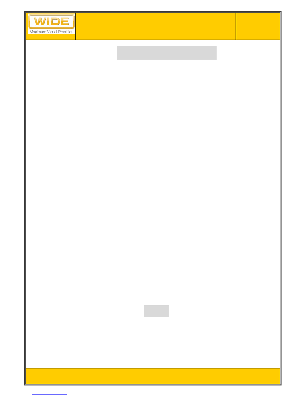
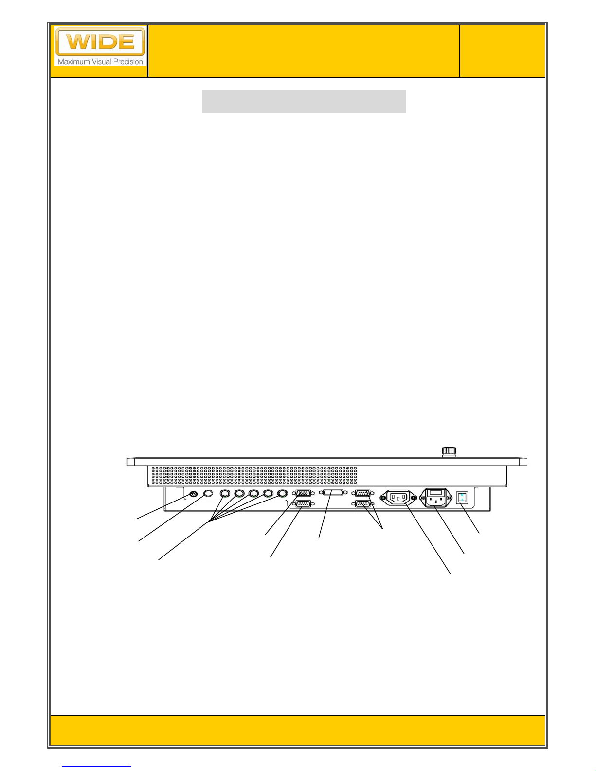
INPUT DIAGRAM
BNC and D-sub input connectable to an y source compatible to general CRT monitor
Digital input fully compatible to DVI-D Standard of VESA DDWG
Chain of Power just one level throug h power output totally
Serial control for SAW Touch screen(option)
DC power (option) : refer 1.1.8 and 1.2. 1.
Composite In
BNC In
D-sub In
S-Video In
DVI-D In
Serial Interface
Power Input
Power output
Power Switch
Touch screen Serial
Control(option)
Issued Date
Revision Status
Title
Page No.
7 / 45
V2.3
2009-04-07
IDP2130HB / IDP2130TS
(AL21NUX)
1 TECHNICAL SPECIFICATIONS
1.1 ELECTRO-OPTICAL SPECIFICATIONS
1.1.1 Screen Specifications
1.1.1.1 Panel Technologies
AMLCD (Active Matrix Liquid Crystal Display) technology
Amorphous silicon TFT (Thin Film Transistor) technology
1.1.1.2 Screen Dimensions
Aspect ratio 4:3
Active screen size:
432.0 (H) x 324.0 (V) mm (17.01” x 12.76”)
540.0 mm (21.3”) diagonal
1.1.1.3 Display colors
16,777,216 true colors (8-bit), 256 grey scales
1.1.1.4 Resolution
1600 (H) x 1200 (V) pixels
Pixel arrangement: RGB (Red dot, Green dot, Blue dot) Vertical Stripe
Pixel pitch: 0.270 (W) x 0.270 (H) mm
1.1.1.5 Display mode
Normally Black
1.1.2 Optical Characteristics
1.1.2.1 Protective Filter Glass
Clear, tempered glass
Anti Reflective Film and Anti-St atic Treatment
1.1.2.2 Luminance (Brightness)
450 cd/m² (max. typical on LCD)
430 cd/m² (max. typical on Protective Filter Glass)
400 cd/m² (max. typical on touch screen)
Dimming Ratio: 1000 to 1
Luminance uniformity: 1.3max (w/o protector glass or touch screen)
1.1.2.3 Contrast ratio
450 : 1 (typical on LCD)
1.1.2.4 Viewing Angle: At the contrast ratio > 10:1
Horizontal: +/- 85 (typical)
Vertical: +/- 85 (typical)
1.1.2.5 Response time @ 25C ambient
Ton + Toff (Black White): 16 ms (typical)
Issued Date
Revision Status
Title
Page No.
8 / 45
V2.3
2009-04-07
IDP2130HB / IDP2130TS
(AL21NUX)
1.1.3 Input Signal Specifications
IDP2130HB provides maximum five (5) input signal interfaces, 2 x Analog(BNC,D-sub) Input(separate/
composite/SOG),1x Digital Input, 1xCVBS input and 1xS-video(interlaced NTSC and PAL).
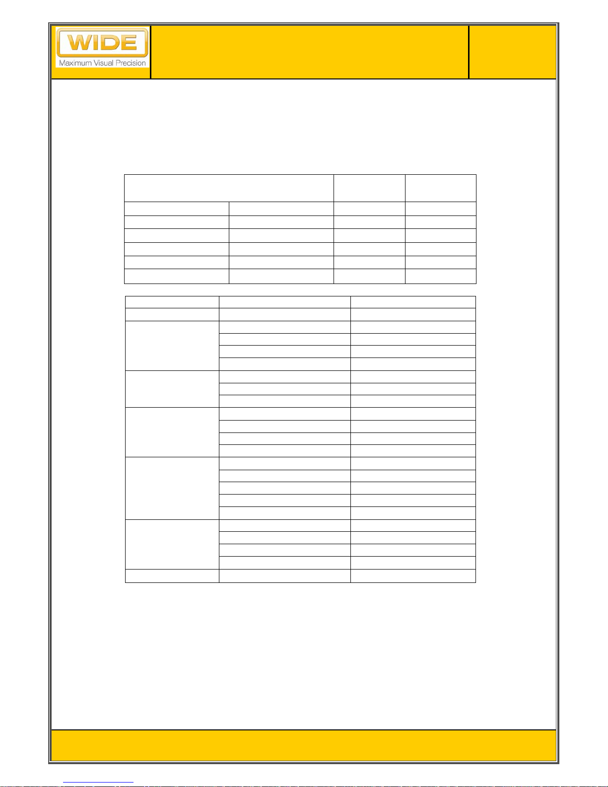
Standard input resolution is UXGA(1600 x 1200 pixels)
Other resolutions are supported as specified below. Automatic up-scaling is provided for input signals with
resolutions less than the standard input resolution 16 00x 1200 pixels.
Resolution
Hsync
(KHz)
Vsync
(Hz)
VGA 640 x 480 31.0 - 43.0 60.0 - 85.0
SVGA 800 x 600 35.0 - 53.7 56.0 - 85.0
XGA 1024 x 768 48.4 - 68.3 60.0 - 85.0
SXGA 1280 x 1024 64.0 – 91.2 60.0 - 85.0
UXGA(analog) 1600 x 1200 75.0 – 93.8 60.0 - 75.0
UXGA(digital) 1600 x 1200 75
60.0
- Specified support resolutions
Resolution H-Frequency (kHz)/(polarity) V-Frequency(Hz)/(polarity)
1600x1200(digital)
75(+) 60(+)
1600x1200(analog)
93.75(+) 75(+)
87.5(+) 70(+)
81.25(+) 65(+)
75(+) 60(+)
1280x1024
91.146(+) 85(+)
79.976(+) 75(+)
63.981(+) 60(+)
1024x768
68.667(+) 85(+)
60.023(+) 75(+)
56.476(-) 70(-)
48.363(-) 60(-)
800x600
53.674(+) 85(+)
46.875(+) 75(+)
48.1(+) 72(+)
37.879(+) 60(+)
35.1(+) 56(+)
640x480
43.269(-) 85(-)
37.5(-) 75(-)
37.7(-) 72(-)
31.469(-) 60(-)
720x400 31.469(-) 70(+)
1.1.3.1 Analog Input
Analog RGB input signal shall be as follows:
Video Signal Level: 0.714 Vp-p nominal
Video Signal Polarity: Positive (Black to White). Polarity is detected automatically.
Both 0 V to +0.714 Vp-p and -0.714 V to 0 Vp-p is allowed.
Video Input Impedance: 7 5 Ohm terminated (RGB Video Signal)
Sync: TTL voltage levels, External Separate H & V Sync.
Interlace: Non-interlaced
1.1.3.2 Input Selection
In case multiple input source is connected, input to be displayed can be selected by:
Issued Date
Revision Status
Title
Page No.
9 / 45
V2.3
2009-04-07
IDP2130HB / IDP2130TS
(AL21NUX)
Manual: Operator can select the input manually using control panel.
1.1.4 Controls of the Display
1.1.4.1 Control via OSD(On Screen Display)
Control block with the push buttons is available: Menu, Select, ◀ and ▶.
Settings are selected by the menu that guides you through the OSD menu.
Control block also has Volume for dimming brightness control.
Control block also has LED indicators, refer to 1.1.5.
1.1.5 LED Indicator
Fault information in available by LED indicators
Normal : Green indicator
Soft Power Off: Amber indicator
No signal : Amber Blinking (every 1 second) indicator
System Fault : Red indicator
1.1.6 Power Supply Specification
1.1.6.1 Voltage range
AC power : 90 – 264Vac , 47 ~63Hz, 1.0A at 230Vac
DC power(option) : 24Vdc
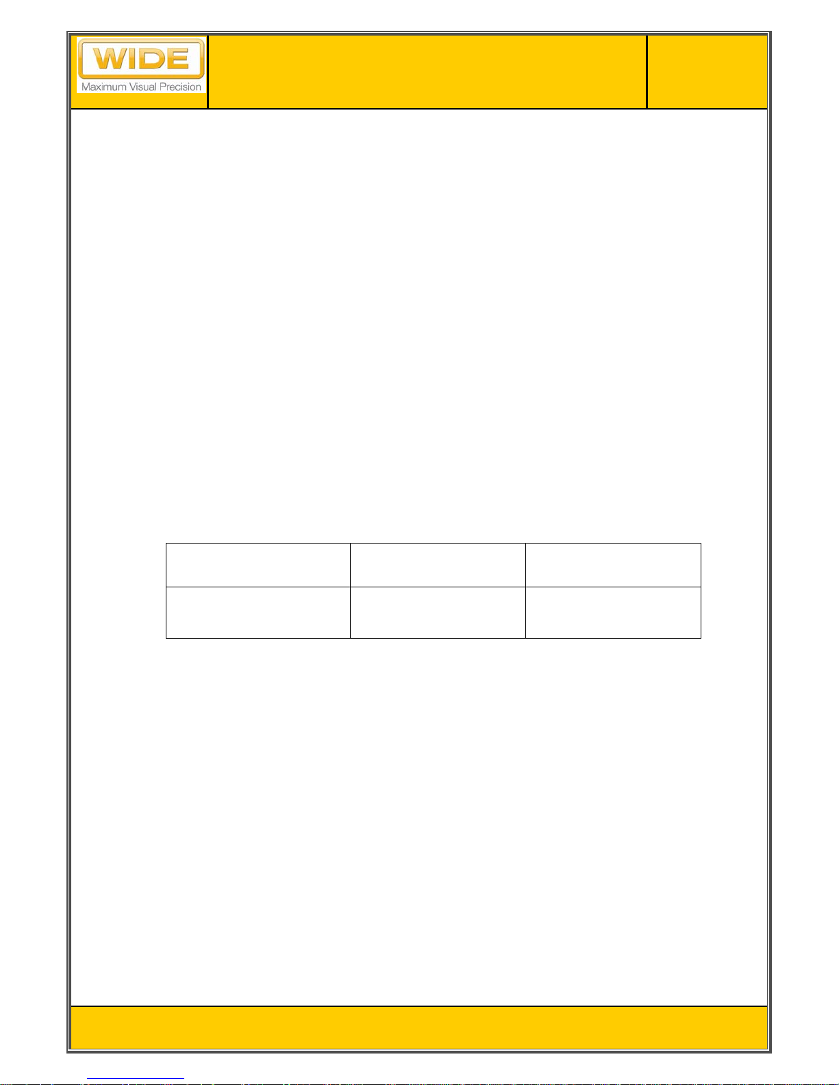
1.1.6.2 Power consumption
Normal
Max.
(100% Light output)
IDP2130HB 90 W 100W
1.1.6.3 Power variation protection
Unit will not be damaged when Voltage transients remain within value as defined in the applicable voltage
range
1.1.6.4 Over-temperature protection
When the internal temperature gets above than the warning level (65℃), the light output of the backlight is
half. And, LED blinks as red color
When the internal temperature reaches above the critical Value (80℃), the light output of the backlight is
turned off. And, LED blinks as red color
When the internal temperature gets below than the safe level (64℃), the light output of the backlight is
restored. And, LED recovers to green.
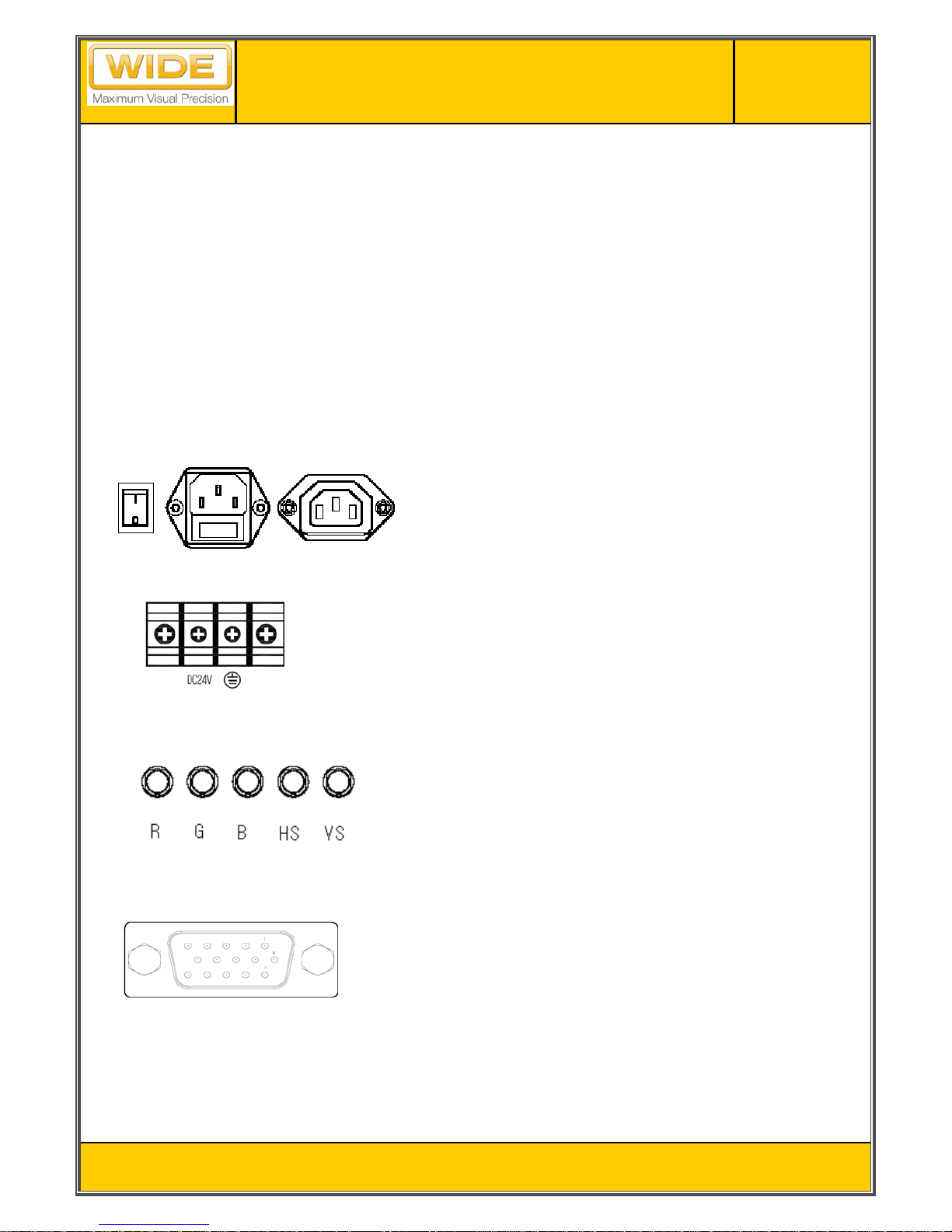
1.1.7 Connectors
1.1.7.1 Power connectors
Standard: IEC type connector
Issued Date
Revision Status
Title
Page No.
10 / 45
V2.3
2009-04-07
IDP2130HB / IDP2130TS
(AL21NUX)
1.1.7.2 Input signal connectors
Analog Input: 15p Dsub and 5 Coaxial BNC connectors for R, G, B, HS and VS
Digital input: DVI-D connectors
CVBS input: RCA connectors
S-video input: 4P mini DIN connectors
1.1.7.3 Interface connectors for remote control
Remote Control (maintenance only): 1 x 9p Dsub female and 1 x 9p Dsub male
Touch screen serial control (Option): 9p Dsub female
1.1.8 Connection & PIN Assignment
Power Input / output
DC Power Input (option)
Analog Input (BNC)
Analog Input (D-Sub)
● 90-264Vac, 47~63Hz with double pole / neutral fusing,
250V F3.15AL
● Disconnect power before changing fuse
● Chain thru power output to limit to one level totally
● R : Analog Red Signal Input (0.7 Vpp, 75 ohm)
● G : Analog Green Signal Input (0.7 Vpp, 75 ohm)
● B : Analog Blue Signal Input (0.7 Vpp, 75 ohm)
● HS : Horizontal Sync Signal Input (TTL)
● VS : Vertical Sync Signal Input (TTL)
● Connection Type : 5 x BNC
● Connection Ty pe : 15p D-aub Female (Analog only support)
1. Red
2. Green
3. Blue
4. Ground
5. DDC Ground
6. Red Ground
7. Green Ground
8. Blue Ground
9. back up
10. sync Ground
11. Ground
12. DDC Data
13. H sync
14. V sync
15. DDC Clock
● DC Terminal Block : BR-1200YD-2P
● 24Vdc
Issued Date
Revision Status
Title
Page No.
11 / 45
V2.3
2009-04-07
IDP2130HB / IDP2130TS
(AL21NUX)
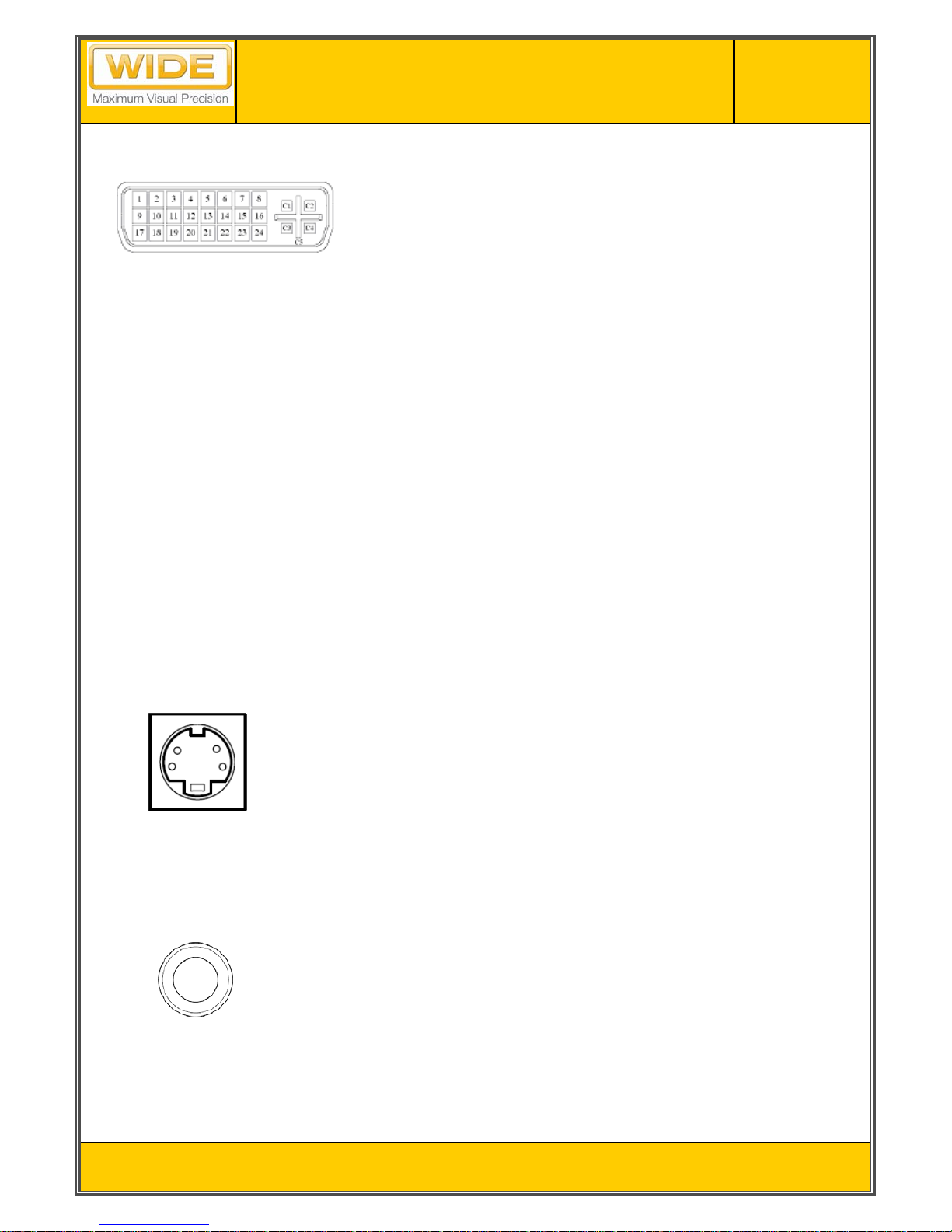
Digital Input
S-Video
CVBS
● Connection Ty pe : 29p DVI-I Female (Digital only support)
1. TMDS Data 2-
2. TMDS Data 2+
3. TMDS Data 2/4 Shield
4. TMDS Data 4-
5. TMDS Data 4+
6. DDC Clock
7. DDC Data
8. No Connection
9. TMDS Data 1-
10. TMDS Data 1+
11. TMDS Data1/3 Shield
12. TMDS Data 3-
13. TMDS Data 3+
14. +5V power
15. Ground (Return for +5V)
16. Hot Plug Detection
17. TMDS Data 0-
18. TMDS Data 0+
19. TMDS Data 0/5 Shield
20. TMDS Data 5-
21. TMDS Data 5+
22. TMDS Clock Shield
23. TMDS Clock+
24. TMDS Clock-
C1 ~ C5 : No Connection
● Connection T y pe : 4-pin DIN Jack
1. GND
2. LUMA
3. CROMA
4. GND
● Connection Type : RCA Jack
Issued Date
Revision Status
Title
Page No.
12 / 45
V2.3
2009-04-07
IDP2130HB / IDP2130TS
(AL21NUX)
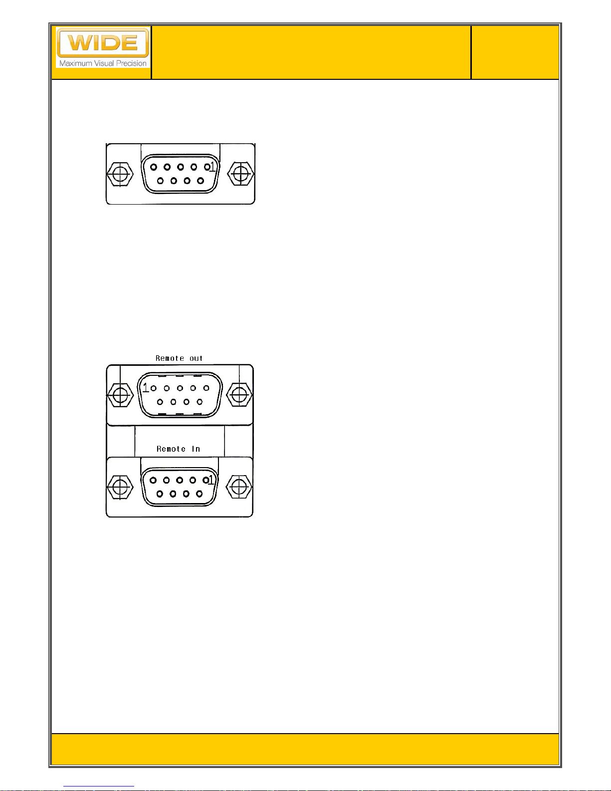
Control Interface
Serial Interface
Touch screen serial control (option)
● Touch screen serial control(female)
1. –DCD("carrier detect", handshake='0'
when controller power on)
2. RXD (serial data from controller to host)
3. TXD (serial data from host to controller)
4. DTR ("data terminal ready", handshake='0'
when controller may send )
5. SG (signal ground)
6. -DSR ("data set ready", handshake='0'
when controller power on)
7. -RTS ("ready to send", handshake='0'
when controller may send)
8. CTS (used as "ready to receive", handshake='0'
when host may send)
9. RI (not used)
● Maintenance Only ( Available for qualified technician )
Issued Date
Revision Status
Title
Page No.
13 / 45
V2.3
2009-04-07
IDP2130HB / IDP2130TS
(AL21NUX)
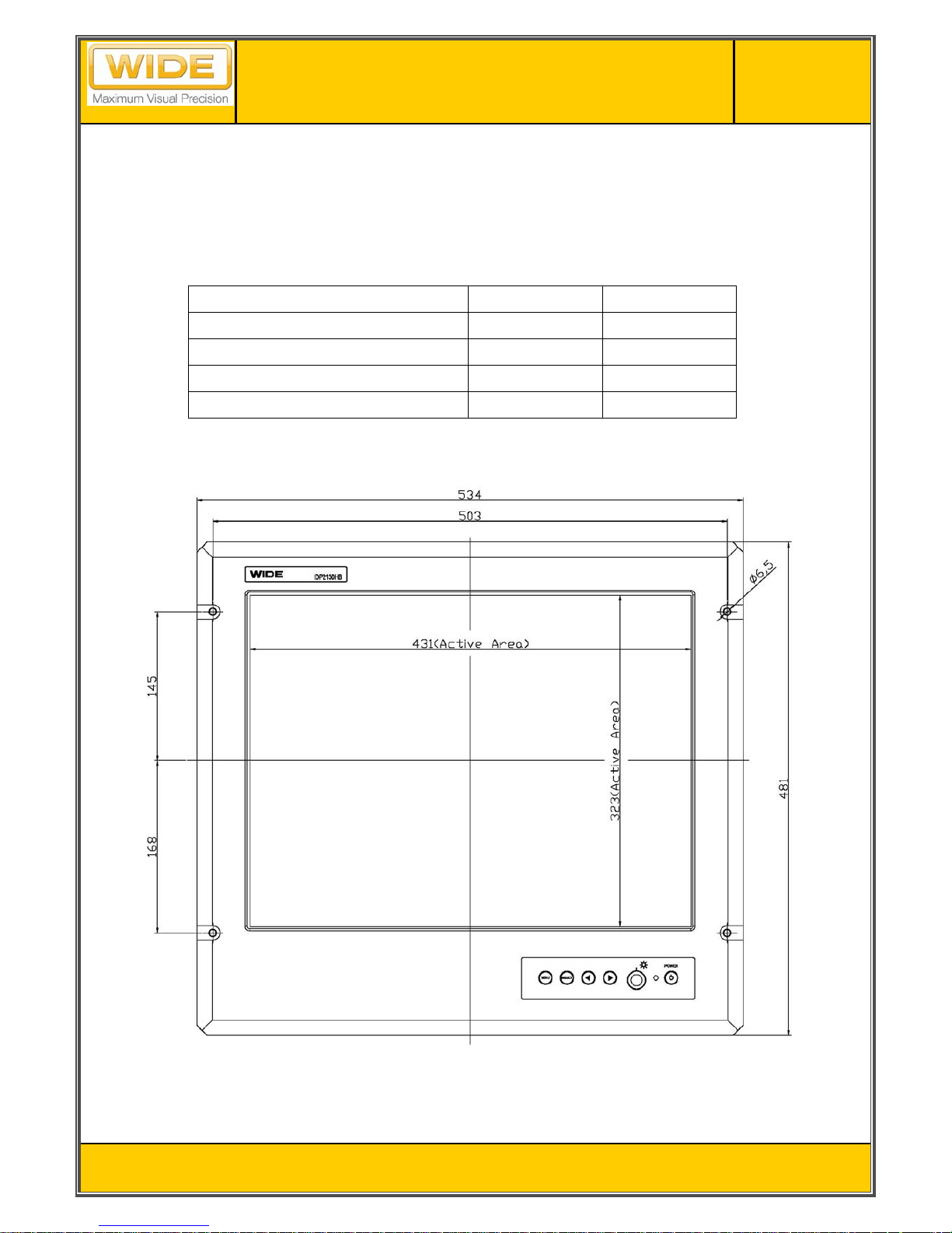
1.2 MECHANICAL SPECIFICATIONS
1.2.1 Dimension and Weight (Rack mount )
The dimension of the unit is as shown in the table below:
Monitor only Packing
Height (mm / inch) 481 / 18.94 780/ 30.71
Width (mm / inch) 534 / 21.02 790/ 31.10
Depth (mm / inch) 95.2 / 3.75 297.5/ 11.72
Weight (kg / lbs) 11.5 / 25.35 16.0 / 35.27
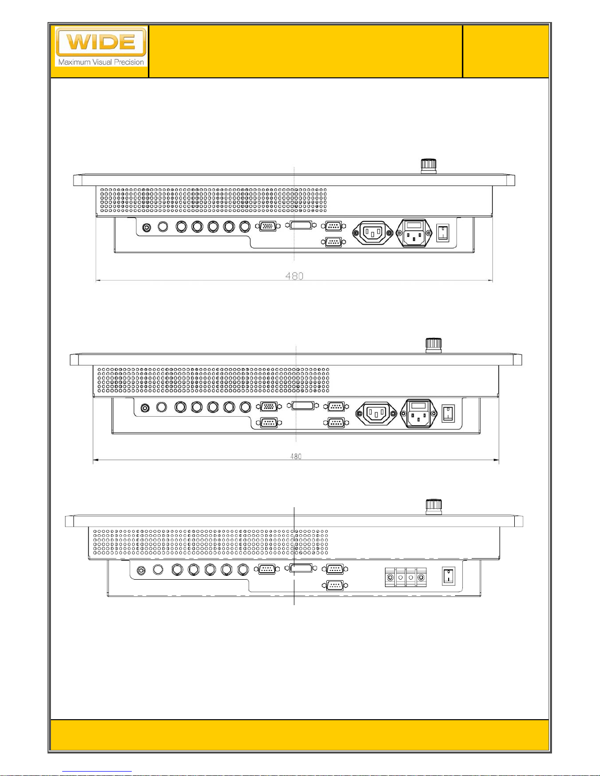
The following figures show a chassis version mechanical dimension. IDP2130HB basically provides three input
connectors and all connectors are located the bottom side of monitor.
< IDP2130HB/TS Front View : unit mm >
Issued Date
Revision Status
Title
Page No.
14 / 45
V2.3
2009-04-07
IDP2130HB / IDP2130TS
(AL21NUX)
< IDP2130HB Bottom View >
< IDP2130TS Bottom View >
< IDP2130HB Bottom View (DC power option)>
 Loading...