


BlueGate 2100
Administrator’s Guide
July 26, 2001
Document Number: BG2100-PROJ-UM-010501-0619
Version: 1.4
Confidential and Proprietary Information
Wireless Internet and Data Communication
9645 Scranton Road, Suite 205
San Diego, CA 92121
Phone: 858.453.8400
Fax: 858.453.5735
Email
Technical Support: support@widcomm.com
Information: info@widcomm.com

BlueGate 2100
FCC STATEMENT
WIDCOMM, Inc., 9645 Scranton Road, Suite 205, San Diego, CA 92121, 858-453-8400.
BlueGate, PKLWBG-2100.
This device complies with part 15 of the FCC Rules. Operation is subject to the following
two conditions: (1) This device may not cause harmful interference, and, (2) This device
must accept any interference received including interference that may cause undesired
operation.
Per CFR 47, PART 15, Paragraph 15.21: User changes or modifications not expressly
approved by the party responsible for compliance could void the users authority to
operate the equipment.
Application PKLWBG-2100
Additional Information for the FCC approval of Widcomm Inc.’s BlueGate 2100
RF Exposure Statement
IMPORTANT NOTE: To meet FCC RF exposure compliance requirements the following
antenna installation and device operating configurations must be satisfied:
BlueGate 2100 must be wall or ceiling mounted or placed on a surface such that a
minimum normal operating distance of 20 centimeters is maintained from the human
body at all times.
LICENSED SOFTWARE
© Copyright 2000 – 2001, WIDCOMM, Inc. (“WIDCOMM”). All rights reserved.
Warning:
Copyright law and international treaties protect this software and accompanying
documentation. Unauthorized reproduction or distribution of this software, or any portion
of it, may result in severe civil and criminal penalties, and will be prosecuted to the
maximum extent possible under the law.
Use of this software is governed by the terms of the end user license agreement that
accompanies or is included with such software. Unless otherwise noted in the end user
license agreement, or herein, no part of the documentation accompanying this software,
whether provided in printed or electronic form may be reproduced in any form, or stored
in a database or retrieval system, or transmitted in any form or by any means, or used to
make any derivative work (such as translation, transformation, or adaptation) without the
express, prior written consent of WIDCOMM.
Trademark(s) ™, Service Mark(s)
WIDCOMM, the WIDCOMM logo, and BlueGate are trademarks of WIDCOMM, Inc.
Bluetooth and the Bluetooth logos are trademarks owned by Bluetooth SIG, Inc., U.S.A.
and licensed to WIDCOMM, Inc.
Netscape is a registered trademark of Netscape Communications Corporation in the U.S.
and other countries. Navigator is also a trademark of Netscape Communications
Corporation and may be registered outside the U.S.
Other brand and product names may be registered trademarks, service marks, or
trademarks of their respective holders.
SM,
and Registered Trademark(s) ®
July 26, 2001 WIDCOMM, Inc., Proprietary and Confidential
i

BlueGate 2100 Table of Contents
Table of Contents
1 INTRODUCTION .................................................................................................... 1
2 KIT CONTENTS...................................................................................................... 2
3 INSTALLATION ..................................................................................................... 3
3.1 POWER CORD AND ETHERNET CABLE INSTALLATION.....................................................3
3.2 WALL OR CEILING INSTALLATION................................................................................. 4
4 RESET BLUEGATE 2100 ........................................................................................ 5
5 FIND BLUEGATE 2100’S IP ADDRESS .................................................................. 6
5.1 IP ADDRESS IN A DHCP ENVIRONMENT ........................................................................6
5.2 IP ADDRESS IN A NON-DHCP ENVIRONMENT ............................................................... 7
6 ACCESS THE INTERNAL WEB SERVER .............................................................. 8
6.1 IN A DHCP ENVIRONMENT ............................................................................................8
6.2 IN A NON-DHCP (PRIVATE NETWORK) ENVIRONMENT ....................................................9
7 USER INTERFACE ............................................................................................... 10
7.1 HOME PAGE................................................................................................................ 10
7.2 CONFIGURATION.........................................................................................................11
7.2.1 Identity ........................................................................................................12
7.2.2 Network Settings ..........................................................................................13
7.2.3 Network Address Translation (NAT) .............................................................. 14
7.2.4 Point-to-Multipoint .......................................................................................14
7.2.5 Authorization................................................................................................ 15
7.2.6 Authentication .............................................................................................. 16
7.2.7 Simple Network Management Protocol (SNMP)..............................................17
7.2.8 Login ...........................................................................................................18
7.3 UTILITIES ...................................................................................................................19
7.3.1 Command Line .............................................................................................19
7.3.2 Ping ............................................................................................................. 20
7.3.3 NS Lookup...................................................................................................21
7.4 DIAGNOSTICS..............................................................................................................22
7.4.1 DHCP ..........................................................................................................22
7.4.2 ARP............................................................................................................. 22
7.4.3 Routing ........................................................................................................22
7.4.4 Authentication .............................................................................................. 22
7.5 STATISTICS ................................................................................................................. 23
7.5.1 History ......................................................................................................... 23
7.5.2 IP Packet Statistics ........................................................................................23
7.5.3 Media Access Control (MAC) Statistics..........................................................23
7.6 SYSTEM ......................................................................................................................24
7.6.1 Restart BlueGate 2100...................................................................................24
7.6.2 Reset BlueGate 2100 to Factory Defaults ........................................................ 24
7.6.3 Perform Software Upgrade ............................................................................24
7.7 HELP ..........................................................................................................................24
8 COMMAND LINE ENTRY .................................................................................... 25
8.1 ? OR HELP ................................................................................................................. 25
8.2 ARP ...........................................................................................................................25
8.3 AUTHENTICATE .....................................................................................................25
8.4 BGIPADDR ...............................................................................................................25
8.5 CONFIG ....................................................................................................................26
8.6 CONSTANTPIN ........................................................................................................26
July 26, 2001 WIDCOMM, Inc., Proprietary and Confidential
ii

BlueGate 2100 Table of Contents
8.7 DEVICEIPADDR ......................................................................................................26
8.8 DEVICENAME ......................................................................................................... 26
8.9 DNS ...........................................................................................................................27
8.10 ENABLEDHCP .........................................................................................................27
8.11 ENABLENAT ............................................................................................................27
8.12 ENCRYPT .................................................................................................................27
8.13 GATEWAY ............................................................................................................... 28
8.14 MULTIPOINT ...........................................................................................................28
8.15 NSLOOKUP ..............................................................................................................28
8.16 PASSWD....................................................................................................................28
8.17 PINCODE .................................................................................................................. 29
8.18 PING..........................................................................................................................29
8.19 RESET.......................................................................................................................29
8.20 ROUTE......................................................................................................................29
8.21 SERVICENAME ....................................................................................................... 30
8.22 STATISTICS OR STATS_DISP..................................................................................30
8.23 SUBNET ....................................................................................................................30
8.24 USERLOGIN .............................................................................................................30
8.25 USERNAME .............................................................................................................. 31
8.26 VERSION OR VER .................................................................................................... 31
9 TROUBLESHOOTING .......................................................................................... 32
9.1 GENERAL....................................................................................................................32
9.2 BLUEGATE 2100 FAILS DURING POWER UP .................................................................32
9.3 ETHERNET LIGHT IS OFF OR DOES NOT BLINK ........................................................... 33
9.4 BLUETOOTH LIGHT DOES NOT BLINK..........................................................................33
9.5 ADMINISTRATIVE USERNAME AND/OR PASSWORD FORGOTTEN.....................................33
9.6 RETURN BLUEGATE 2100 TO THE FACTORY-DEFAULT SETTINGS .................................33
9.7 BLUETOOTH DEVICE ADDRESS IS MISSING ...................................................................33
9.8 MEDIA ACCESS CONTROL (MAC) ADDRESS IS MISSING ...............................................33
9.9 CANNOT FIND BLUEGATE 2100’S IP ADDRESS WITH FINDIP........................................ 34
9.9.1 The Dialog Box Appears ...............................................................................34
9.9.2 The Dialog Box Does NOT Appear ................................................................34
9.10 CANNOT FIND BLUEGATE 2100’S IP ADDRESS WITH THE JAVA APPLET
IN UNIX ENVIRONMENT.............................................................................................. 34
9.10.1 The Dialog Box Appears ...............................................................................34
9.10.2 The Dialog Box Does NOT Appear ................................................................ 35
9.11 BLUEGATE 2100 DOES NOT SHOW UP WHEN A DEVICE INQUIRY IS MADE....................35
9.12 DIFFERENTIATING BETWEEN MULTIPLE BLUEGATE 2100 DEVICES..............................35
9.13 CANNOT DISCOVER SERVICES ..................................................................................... 36
9.14 CANNOT CONNECT TO THE LAN ACCESS PROFILE SERVICE.........................................36
9.15 CAN’T ESTABLISH MORE THAN ONE LAP CONNECTION ................................................36
APPENDIX A—AN INTRODUCTION TO BLUETOOTH ...........................................A-1
APPENDIX B—CROSSOVER CABLE CONNECTIONS DIAGRAM...........................B-1
APPENDIX C—FIND IP ADDRESS IN A NON-WINDOWS ENVIRONMENT ............C-1
July 26, 2001 WIDCOMM, Inc., Proprietary and Confidential
iii

BlueGate 2100 Lists of Tables and Figures
List of Tables
Table 1: BlueGate 2100’s factory-default critical NVRAM settings. ................................................5
Table 2: Fatal POST Blink Codes. ................................................................................................32
List of Figures
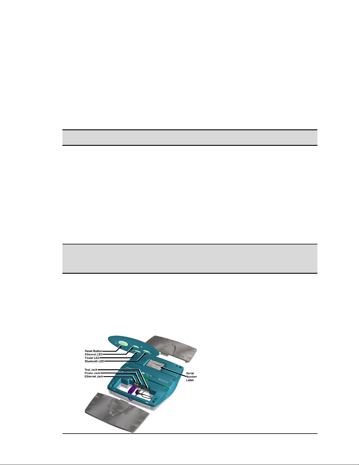
Figure 1: BlueGate 2100 connector and LED locations. ..................................................................3
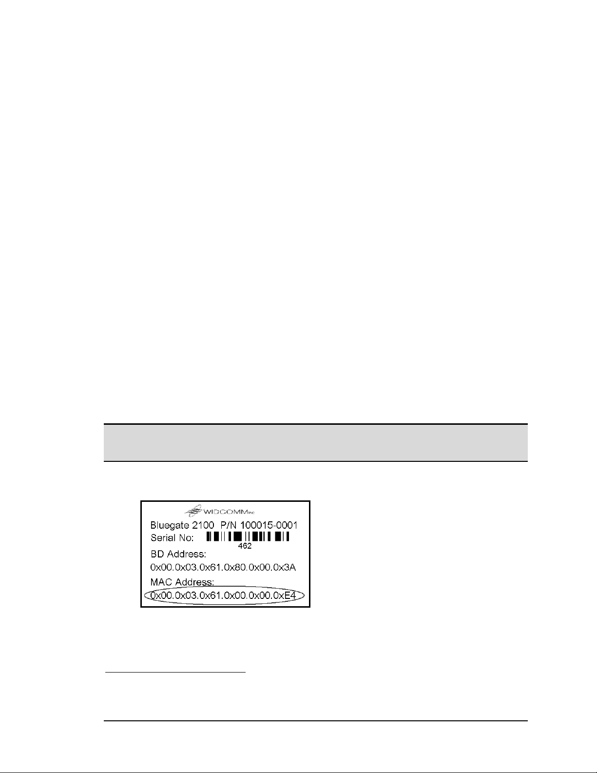
Figure 2: BlueGate 2100's serial number label. ............................................................................... 6
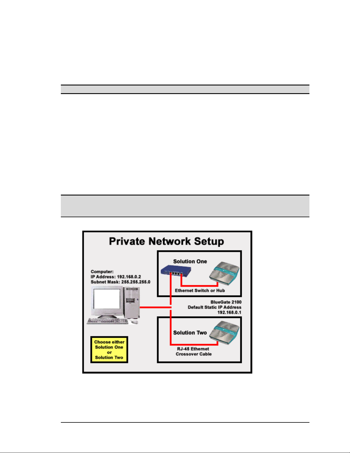
Figure 3: Two-node private network options...................................................................................7
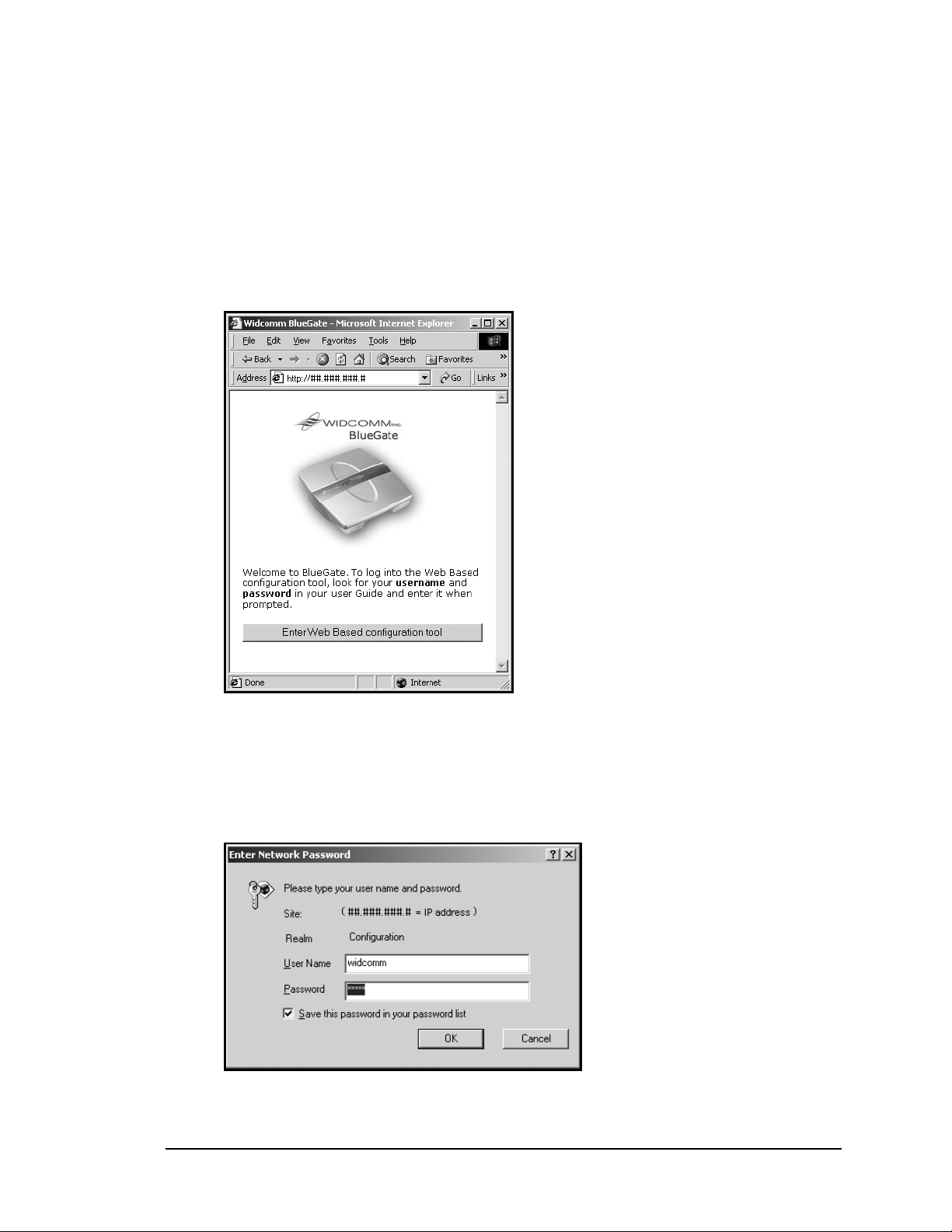
Figure 4: BlueGate 2100's internal Web server > Welcome page.....................................................8
Figure 5: Enter Network Password dialog box. ............................................................................... 8
Figure 6: BlueGate 2100's internal Web server > Home page........................................................10
Figure 7: Configuration tab > Identity option (inset).....................................................................12
Figure 8: Configuration tab > Authorization option......................................................................15
Figure 9: Configuration tab > Authentication option > fixed PIN code.......................................... 16
Figure 10: Configuration tab > Authentication option > individual PIN codes. ...............................17
Figure 11: Utilities tab > Command Line option > List of commands.............................................. 19
Figure 12: Utilities tab > Ping option. .............................................................................................20
Figure 13: Utilities tab > NS Lookup option....................................................................................21
Figure 14: Crossover cable connections................................................................................................. B-1
Figure 15: Java applet and the IE dialog box (inset) that displays the IP address ............................C-2
July 26, 2001 WIDCOMM, Inc., Proprietary and Confidential
iv

BlueGate 2100 Introduction
1 Introduction
BlueGate™ 2100 provides access to a local area network (LAN) using wireless
technology. It is Bluetooth Specification 1.1 compliant.
Devices that can access the network through BlueGate 2100 are Personal Digital
Assistants (PDAs), computers, or other Bluetooth-enabled devices that support the
industry standard L
Specification Version 1.1.
Configuration information is saved in internal Non-Volatile Random Access Memory
(NVRAM) and preserved even when power is lost.
An on-board, internal Web server is accessed to set up, diagnose, and configure
BlueGate 2100.
A browser
1
is used to access the internal Web server from a computer on the same
network subnet.
From the browser, access the internal Web server to:
• Configure BlueGate 2100 for proper network operation.
• Change the user-friendly device name of BlueGate 2100.
• Access network diagnostic tools.
• View BlueGate 2100 network statistics.
• Upgrade BlueGate 2100 software.
AN Access using PPP Profile (LAP) portion of Bluetooth
1
Browsers compatible with BlueGate 2100 are Microsoft® Internet Explorer, version 5.0 or later,
and Netscape
C will not work with Netscape Navigator.
™
Navigator™, version 4.7 or later. However, the Java applet described in Appendix
July 26, 2001 WIDCOMM, Inc, Proprietary and Confidential
1

BlueGate 2100 Kit Contents
2 Kit Contents
The BlueGate 2100 kit includes:
• A BlueGate 2100 network access point:
Dimensions (HxDxW): 160x60x160 mm (6.3x2.4x6.3 in.).
Weight: 350 g (12.3 oz) excluding power supply.
• An external power adapter; cord length is 6 ft.
• A standard Ethernet cable with an RJ-45 connector on each end;
cable length is 7 ft. (2 m).
• Hardware installation components:
Four (4) mounting screws, Rounded Head Philips, #8, 1 ½ in.
Four (4) self-drilling wall anchors, #8, 1 ¼ in.
Wall/Ceiling mounting template.
• A compact disc that contains the BlueGate 2100 documentation and
support software.
• A Start Here quick-start guide.
• Mounting instructions and template.
July 26, 2001 WIDCOMM, Inc, Proprietary and Confidential
2
BlueGate 2100 Installation
3 Installation
Before installing BlueGate 2100, you should be familiar with basic local area network
(LAN) and Bluetooth concepts.
For a non-technical overview of key Bluetooth concepts refer to Appendix A—An
Introduction To Bluetooth.
3.1 POWER CORD AND ETHERNET CABLE INSTALLATION
1. Mount BlueGate 2100 on the wall or ceiling or place it on a flat surface away
from heat, moisture, open flames, microwave devices, and 2.4 GHz
telecommunication devices (for example, 802.11b LAN adapters). See also the
RF Exposure Statement on page i.
NOTE: See Section 3.2 for additional information on mounting BlueGate 2100 on the wall
or ceiling.
2. Use the Ethernet cable provided in the kit to connect BlueGate 2100 to the local
area network. See Figure 1 for the location of BlueGate 2100’s Ethernet jack.
The Ethernet cable can be plugged into a network switch or network hub, or into
a hardwired wall jack that connects to the network. Consult your network
administrator if you are unsure of where or how to establish a physical
connection to the network.
Place the other end of the Ethernet cable securely into the Ethernet jack (RJ-45
connector) on BlueGate 2100. The Ethernet LED blinks off and on depending on
Ethernet activity.
Route the network cable away from other cables that may cause electrical
interference. Avoid routing the cable through areas where it will be stepped on,
tripped over, or damaged in any way.
NOTE: Telephone cables often use the same type of connector as network cables; some
wall plates, especially in office environments, have both telephone and network
jacks in the same wall plate. When connecting through a wall plate of this type
verify the physical connection between the jack and the network.
3. Insert the small circular power plug into the power jack on the back of
BlueGate 2100 and then plug the power supply into a wall outlet (120-220VAC,
60-50 Hz). When power is applied the bottom light emitting diode (LED) will
blink for 6 seconds and then stay on continuously.
If the LAN is 10Base-T or 100Base-T and a Dynamic Host Configuration Protocol
(DHCP) server is available, BlueGate 2100 is ready to use.
Figure 1: BlueGate 2100 connector and LED locations.
July 26, 2001 WIDCOMM, Inc, Proprietary and Confidential
3

BlueGate 2100 Installation
3.2 W
Required materials and tools:
Install template and drywall anchors:
Mount BlueGate 2100:
ALL OR CEILING INSTALLATION
• Adhesive tape.
• #2 Philips head screwdriver or drill/driver with Philips bit.
NOTE: The self-drilling anchors are for drywall
installation only. The anchors are not
recommended for use in acoustical ceiling
tiles or other types of wall / ceiling materials.
1. Decide where BlueGate 2100 will be mounted keeping in mind:
The lengths of the Ethernet cable and power cord.
The location of the Bluetooth-enabled devices that will use BlueGate 2100’s
service. Typically devices must be within 30 meters of BlueGate 2100; walls
and other obstructions may shorten this distance.
2. Tape the mounting template to the installation location and use a nail or other
small pointed object to mark the locations of the screw anchors.
3. Remove the template.
4. Using a screwdriver or drill/driver, install the self-drilling drywall anchors:
a) Place the screwdriver or driver/drill into recess of anchor.
b) Press the anchor into the drywall while turning the anchor clockwise until it
is seated flush with the wall.
1. Slide the covers outward from the center of BlueGate 2100 to remove them.
NOTE: Do not lift or pry the covers.
2. Complete the power cord and Ethernet cable installation described in Section 3.1
(also described in the Start Here booklet).
3. Hold the base of BlueGate 2100 firmly against the wall or ceiling aligning the
device’s screw holes over the wall anchors.
4. Using the four (4) included Philips head screws, secure BlueGate 2100 to the
wall anchors.
5. Replace the covers.
July 26, 2001 WIDCOMM, Inc, Proprietary and Confidential
4

BlueGate 2100 Reset BlueGate 2100
4 Reset BlueGate 2100
BlueGate 2100 can be reset to the factory-default reset parameters shown in Table 1 in
several ways:
1. From within BlueGate 2100’s internal Web server, click
Factory Defaults > Reset BlueGate to Factory Defaults Now.
OR
2. Press the hardware reset button (see Figure 1):
a) ALL CRITICAL PARAMETERS—hold the hardware reset button down
for more than five seconds to reset all critical Non-Volatile Random Access
Memory (NVRAM) parameters to their factory default settings (see Table 1).
BlueGate 2100 will reboot three seconds after the button is released.
b) ADMINISTRATOR’S USER NAME AND PASSWORD ONLY—press
the hardware reset button briefly (less than five seconds) to reset ONLY the
administrator’s user name and password to the factory default settings.
BlueGate 2100 does NOT reboot.
Table 1: BlueGate 2100’s factory-default critical NVRAM settings.
BlueGate 2100 Factory-Default Reset Parameters
Parameter Default Setting
Administrator’s user name widcomm (case sensitive)
Administrator’s password admin (case sensitive)
Device name BGNNNNNN (NNNNNN = serial number)
LAN Access Profile (LAP) Service name LAN Access
Antenna Internal
Authentication Off / Disabled
Encryption Off / Disabled
Authorization Off / Disabled
Point-to-Multipoint Disabled
DHCP Enabled
NAT Enabled
Default IP address 192.168.0.1
Fixed IP address Cleared
Gateway Cleared
Subnet Mask Cleared
DNS Server Cleared
Secondary DNS Server Cleared
System > Reset to
NOTE: When BlueGate 2100 is reset in a DHCP environment it is possible for the server to
assign a different IP address to it. See Section 5.1 for information on how to obtain
the new IP address.
July 26, 2001 WIDCOMM, Inc, Proprietary and Confidential
5
BlueGate 2100 Find BlueGate 2100’s IP address
5 Find BlueGate 2100’s IP address
BlueGate 2100 is set up and configured through an internal Web server.
To access BlueGate 2100’s internal Web server you must know the IP address assigned
to BlueGate 2100.
In a Dynamic Host Configuration Protocol (DHCP) environment, BlueGate 2100’s
IP address is dynamically assigned by the DHCP server.
The FindIP application that discovers BlueGate 2100’s dynamically assigned IP address
is included on the BlueGate 2100 compact disc (see Section 5.1).
In a non-DHCP environment BlueGate 2100 defaults to a static IP address that can be
used to access the internal Web server (see Section 5.2).
A Java™ applet
Windows
in a Non-Windows Environment.
5.1 IP ADDRESS IN A DHCP ENVIRONMENT
To discover the dynamically assigned IP address:
1. Insert the BlueGate 2100 compact disc into your CD-ROM drive and wait a few
seconds for the FindIP.exe application to auto-start. If the application does not
auto-start, from the Windows taskbar click
Letter (for example D:\) >
2. On the Welcome to Widcomm’s BlueGate Wizard screen, click
3. When prompted, enter the Media Access Control (MAC) Address from the serial
number label on BlueGate 2100 (Figure 2) located beneath the covers (Figure 1)
and click
4. FindIP returns the IP address. Select the check box to automatically open the
internal Web server home page and click
2
®
is included on the compact disc for environments not operating under
. For more information on the Java applet, see Appendix C—Find IP address
Start > Run > Drive Designation
FindIP.exe.
Next.
Next.
Finish.
NOTE: The FindIP application uses a UDP broadcast packet to interrogate BlueGate 2100
for its assigned IP address. UDP packets are not routed; be sure that a router is
not between BlueGate 2100 and the computer running FindIP.
Section 6 describes how to complete the logon process.
Figure 2: BlueGate 2100's serial number label.
2
An applet is a Java-based program that is downloaded by a browser. See also Appendix C—Find IP
address in a Non-Windows Environment
.
July 26, 2001 WIDCOMM, Inc, Proprietary and Confidential
6
BlueGate 2100 Find BlueGate 2100’s IP address
5.2 IP A
DDRESS IN A NON-DHCP ENVIRONMENT
BlueGate 2100’s internal Web server can also be accessed using a static IP address.
When DHCP is enabled (factory default), the DHCP attempt must first timeout before
attempting to access BlueGate 2100’s internal Web server using the static IP address.
After the DHCP timeout (120 seconds), BlueGate 2100 uses the static IP address.
NOTE: The factory-default static IP address is: 192.168.0.1.
To access BlueGate 2100’s internal Web server using the static IP address, create a twonode private network between a single computer and BlueGate 2100:
1. Connect BlueGate 2100 and the computer (see Figure 3):
Solution One: use standard Ethernet cables to establish a connection through
a switch or hub.
Solution Two: use a crossover cable to create a direct connection. Figure 14
on page B-1 shows the connections for a crossover cable.
2. Configure the computer:
Static IP address of 192.168.0.2.
Subnet mask of 255.255.255.0.
3. Start the browser and enter http://192.168.0.1 in the address field.
4. Click
Go or press the Enter key.
Section 6 describes how to complete the logon process.
NOTE: The default static IP address for BlueGate 2100 can be changed through
the Configuration > Network Settings option. If BlueGate 2100’s static IP address
has been reconfigured, enter the current address.
Figure 3: Two-node private network options.
July 26, 2001 WIDCOMM, Inc, Proprietary and Confidential
7
BlueGate 2100 Access the Internal Web Server
6 Access the Internal Web Server
The following sections describe how to access BlueGate 2100’s internal Web server.
6.1 IN A DHCP ENVIRONMENT
1. Start a supported browser.
2. Enter BlueGate 2100’s IP address (see Section 5.1) in the address area and click
Go or press the Enter key. The welcome page shown in Figure 4 opens in
the browser.
Figure 4: BlueGate 2100's internal Web server > Welcome page.
3. When the
Enter Web Based configuration tool button is clicked, a logon
screen (Figure 5) appears.
4. Enter the user name widcomm.
5. Enter the password admin and click
is displayed.
Figure 5: Enter Network Password dialog box.
OK. The home page (Figure 6, page 10)
July 26, 2001 WIDCOMM, Inc, Proprietary and Confidential
8

BlueGate 2100 Access the Internal Web Server
6.2 I
N A NON-DHCP (PRIVATE NETWORK) ENVIRONMENT
See Section 5.2 for details about setting up a private network:
1. Start a supported browser.
2. Enter http://192.168.0.1 in the address area and click
Enter key. The welcome page shown in Figure 4 opens in the browser.
3. When the
Enter Web Based configuration tool button is clicked, a logon screen
Go or press the
(Figure 5) appears.
4. Enter the user name widcomm.
5. Enter the password admin and click
OK. The internal home page (Figure 6,
page10) is displayed.
Refer to Section 7 for specific configuration options and information on how to use them.
July 26, 2001 WIDCOMM, Inc, Proprietary and Confidential
9
BlueGate 2100 User Interface
7 User Interface
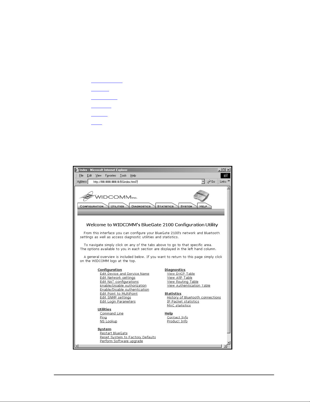
7.1 HOME PAGE
The BlueGate 2100 internal Web server’s user interface is tab-based. The page associated
with each tab has an Options panel that provides access to sub-topics.
There are six tabs:
• Configuration
• Utilities
• Diagnostics
• Statistics
• System
• Help
Click the WIDCOMM logo at the top of any tab to return to the home page shown in
Figure 6.
The home page also contains hyperlinks to each of the sub-topics accessed through
the tabs.
Figure 6: BlueGate 2100's internal Web server > Home page.
.
.
.
.
.
.
July 26, 2001 WIDCOMM, Inc, Proprietary and Confidential
10

BlueGate 2100 User Interface
7.2 C
The Configuration tab provides a means to setup and/or change basic network and
Bluetooth security settings that control:
Settings can also be modified one at a time with command line parameters. See Sections
7.3 and 8 for more information.
The available options are:
To modify an option:
The Current Settings column (Figure 7-D) displays the settings that are in use. Unless the
Current Settings column indicates that settings take effect immediately, BlueGate 2100
must be restarted to implement the changes (see Section 7.6.1).
The Saved Settings column (Figure 7-E) displays the settings that are stored in NVRAM
and is the data that BlueGate 2100 will use the next time it is started, regardless of what
appears in the Current Settings column.
ONFIGURATION
• The identification information that is displayed to other Bluetooth devices.
• The way BlueGate 2100 communicates with the LAN.
• Identity:
Device Name.
Service Name.
• Network Settings:
Dynamic Host Configuration Protocol (DHCP).
IP (Internet Protocol) address.
Gateway.
Subnet Mask.
Primary DNS (Domain Name System) Server.
Secondary DNS Server.
• Network Address Translation (NAT).
• Point-to-Multipoint.
• Authorization:
Define up to seven authorized users (user names and passwords).
• Authentication (Bluetooth security):
Enable encryption.
Configure fixed or individual PIN codes.
• Simple Network Management Protocol (SNMP) settings:
MIB-II Community.
BlueGate MIB Community.
Authentication Failure Trap.
SNMP Manager IP address.
• Login:
Change the administrator’s user name and password.
1. In the Options panel, click the option to be modified (Figure 7-A).
2. Click the
EDIT button (Figure 7-B).
3. In the browser window that appears, fill in or modify the fields and click
(Figure 7-C).
OK
July 26, 2001 WIDCOMM, Inc, Proprietary and Confidential
11

BlueGate 2100 User Interface
The question marks (Figure 7-F), when clicked, provide help and/or additional
information about specific items.
Figure 7: Configuration tab > Identity option (inset).
7.2.1 Identity
Configures the identification information that is displayed to other Bluetooth devices.
• Device Name: helps identify BlueGate 2100 to other Bluetooth devices.
Device Name is limited in length to 100 alphanumeric characters.
To change the Device Name, click the
Example: “My BlueGate 2100 Network Access Point.”
Default Value: “BGNNNNNN” (the letters “BG” followed by the unit’s
• Service Name: the service name that BlueGate 2100 displays to other
Bluetooth devices.
Service Name is limited in length to 100 alphanumeric characters.
To change the Service Name, click the
Example: “ABC123 Co. Network Access.”
Default value: “LAN Access.”
Click
OK to store the changes in NVRAM and update BlueGate 2100’s current settings.
Changes to the Identity settings take effect immediately after OK is clicked.
Click
Cancel to abort the changes and return to the previous screen.
EDIT button, highlight the existing
text, and type the new name.
serial number), for example “BG9123.”
EDIT button, highlight the existing
text, and type the new name.
July 26, 2001 WIDCOMM, Inc, Proprietary and Confidential
12

BlueGate 2100 User Interface
7.2.2 Network Settings
Configures how and where BlueGate 2100 gets the required Internet Protocol (IP)
addresses it needs to function properly.
The default is Dynamic Host Control Protocol (DHCP) enabled.
DHCP Enabled:
When DHCP is enabled:
• BlueGate 2100 is assigned an IP address by the DHCP-enabled LAN server.
• The LAN server handles gateway, subnet, and DNS addressing.
• All of the fields in the Network Settings Information configuration window
appear dimmed and are unavailable.
To enable DHCP select the
Enable option and click OK. BlueGate 2100 must be
restarted for the change to take effect. Restart is explained in Section 7.6.1, page 24.
DHCP Disabled:
To disable DHCP select the Disable option, enter the addresses in dotted decimal
notation (000.000.000.000), and click
OK.
BlueGate 2100 must be restarted for the change(s) to take effect. Restart is explained in
Section 7.6.1, page 24.
• IP address: the IP address of BlueGate 2100.
Example:
10.140.102.8
Default value: “” (blank field, no entry)
• Gateway: the IP address of the LAN gateway to which BlueGate 2100 will route
packets destined for outside networks.
Example:
10.140.0.1
Default value: “” (blank field, no entry)
• Subnet: identifies the subnet to which an IP address belongs.
Example:
255.255.255.0
Default value: “” (blank field, no entry)
• Primary DNS (Domain Name System): the IP address of the primary DNS
server. When a DNS server is provided with a hostname, it returns the host’s
IP address:
Example:
10.140.10.1
Default value: “” (blank field, no entry)
• Secondary DNS: the IP address of the secondary DNS server—used if the
primary DNS server is unavailable or unable to translate a submitted hostname to
an IP address.
Example:
10.140.10.2
Default value: “” (blank field, no entry)
Click
OK to store the changes in Saved Settings. BlueGate 2100 must be restarted for the
change to take effect. Restart is explained in Section 7.6.1, page 24.
Click
Cancel to abort the changes and return to the previous screen.
July 26, 2001 WIDCOMM, Inc, Proprietary and Confidential
13

BlueGate 2100 User Interface
7.2.3 Network Address Translation (NAT)
NAT is an Internet standard that allows a network to use one set of IP addresses for
internal traffic and a different set of addresses for external traffic.
BlueGate 2100 handles address translations between the Local Area Network (external)
and the Bluetooth devices (internal) connected to BlueGate 2100.
The default is NAT enabled.
• When NAT is enabled and:
DHCP is enabled, BlueGate 2100 receives its IP address from the DHCP
server, but internally assigns IP addresses to the devices in its private subnet
(the Bluetooth devices connected to it).
DHCP is disabled, BlueGate 2100 uses a fixed IP address (
Network Settings > Edit > IP Address
) on the external network but assigns
Configuration >
IP addresses to the devices in its private subnet (the Bluetooth devices
connected to it).
• When NAT is disabled and:
DHCP is enabled, Bluetooth devices get their IP address from the
DHCP server.
DHCP is disabled, the IP address for each Bluetooth device must be
configured in BlueGate 2100’s NVRAM.
If both NAT and DHCP are disabled, a range of usable IP addresses must be configured
manually. If either NAT or DHCP is disabled and then the other is also disabled,
a window opens with fields to configure a range of usable IP addresses.
• In the Range Starting From field enter the starting IP address.
• In the No. of IP Addresses in this range field enter the number (< 255) of
addresses to assign and click the
Update button.
7.2.4 Point-to-Multipoint
Point-to-Multipoint refers to BlueGate 2100’s ability to service more than one client at
the same time.
BlueGate 2100’s Point-to-Multipoint ability, when enabled, is limited to seven devices.
To enable/disable Point-to-Multipoint click
OK.
click
EDIT, select the appropriate radio button, and
The default is Point-to-Multipoint disabled.
NOTE: When Point-to-Multipoint is enabled, Bluetooth devices that only support Point-to-
Point will not be able to connect to BlueGate 2100.
July 26, 2001 WIDCOMM, Inc, Proprietary and Confidential
14

BlueGate 2100 User Interface
7.2.5 Authorization
BlueGate 2100 authorization is the process of granting or denying access to a resource.
A user name and password are required.
The default Authorization setting is disabled.
NOTE: BlueGate 2100 authorization is not the same as the Bluetooth authorization
described in Appendix A.
If Authorization is disabled (No), all users are allowed to connect to BlueGate 2100.
If Authorization is enabled (Yes), only specific users can connect to BlueGate 2100.
NOTE: Do not enable Authorization if the connecting device does not support security.
To enable/disable Authorization (Figure 8):
1. Click EDIT, select the appropriate radio button (Yes or No), and click OK.
2. Set up authorized users and passwords:
a) Select a user number from the drop-down list.
b) Enter a user name; 1 to 16 alphanumeric characters (case sensitive).
c) Enter a password; 1 to 16 alphanumeric characters (case sensitive).
NOTE: User names and passwords are case sensitive.
3. Repeat steps 2a through 2c for each user (up to seven) to be authorized and then
click the
Update button.
BlueGate 2100 can store up to seven authorized user names (including the administrator)
and their associated passwords.
The administrator is the first name in the list (User zero); the default setting is
user name = widcomm and password = admin. The remaining user names/password
entries are numbered User one through User six. The authorized user name and password
information also can be re-configured through the command line entry feature (see
Sections 8.16 and 8.25).
Figure 8: Configuration tab > Authorization option.
July 26, 2001 WIDCOMM, Inc, Proprietary and Confidential
15

BlueGate 2100 User Interface
7.2.6 Authentication
Bluetooth Authentication requires a Personal Identification Number (PIN) code before
allowing a client to establish a connection.
There are two types of PIN code:
• Fixed—the same PIN code is used for all devices attempting to connect.
• Individual—each device attempting to connect has its own code.
BlueGate 2100’s Authentication options are:
• Disable.
• Enable using fixed PIN code.
• Enable using individual PIN codes for each connecting device.
The default is disabled.
Selecting either Enable option brings up a window where PIN(s) can be configured and
encryption can be turned on or off.
When enabled, encryption applies only to data transferred between Bluetooth devices—
data transferred via the network is not encrypted.
Encryption is accomplished using the Authentication PIN code as the key; if Authentication is not enabled, the PIN is not used and encryption is not possible.
Notes: Encryption cannot be used unless Authentication is enabled.
Do not enable Authentication if the connecting device does not support security.
Enable using a Fixed PIN code (Figure 9):
1. Select Yes or No to enable/disable encryption.
2. Enter the fixed PIN code to be used by all connecting devices (1 to 16
alphanumeric characters). For example, 9999ABCD is a valid PIN code.
3. Click
Submit.
BlueGate 2100 must be restarted for the change(s) to take effect. Restart is explained in
Section 7.6.1, page 24.
Figure 9: Configuration tab > Authentication option > fixed PIN code.
Enable using Individual PIN codes (Figure 10):
1. Select Yes or No to enable/disable encryption.
2. Set up individual PIN codes:
a) Select a device from the drop-down list.
b) Enter the Bluetooth Device Address (“BD Addr”) associated with that device
in dotted notation.
c) Enter the individual PIN code to be used by the selected device (1 to 16
alphanumeric characters). For example, 9999ABCD is a valid PIN code.
3. Repeat steps 2a through 2c for each device (up to seven) to be authenticated and
then click the
Update button.
July 26, 2001 WIDCOMM, Inc, Proprietary and Confidential
16

BlueGate 2100 User Interface
4. Click the close this window hyperlink to close the Edit Authentication
Information window.
BlueGate 2100 must be restarted for the change(s) to take effect. Restart is explained in
Section 7.6.1, page 24.
Figure 10: Configuration tab > Authentication option > individual PIN codes.
7.2.7 Simple Network Management Protocol (SNMP)
SNMP is implemented in BlueGate 2100 to configure and manage multiple
BlueGate 2100 devices from a central location. BlueGate 2100 supports both SNMP
Version 1 and Version 2 requests.
NOTE: HP® OpenView®3 must be installed in order to implement SNMP settings.
SNMP-compliant devices, called agents, store data about themselves in Management
Information Bases (MIBs) and return this data to the SNMP requesters. BlueGate 2100
supports two MIBs:
• MIB II—standard MIB for Network Management of TCP/IP-based Internets.
• BlueGate Private MIB—to manage all configuration and statistics related to
BlueGate 2100.
Read and write access to each of these MIBs is controlled through the use of
Community Names.
• MIB-II Community Names:
Read—has read access to MIB-II data.
Read-Write—has read and write access to MIB-II data.
• BlueGate MIB Community Names:
Read—has read access to BlueGate MIB data.
Read-Write—has read and write access to BlueGate MIB data.
NOTE: All community names must be unique. The read community for the BlueGate MIB
has read access to the MIB-II MIB. The read-write community for the BlueGate MIB
has read-write access to the MIB-II MIB.
3
The HP OpenView software suite is an Internet and e-services management solution developed
by the Hewlett-Packard Company. For additional information about this software suite go to
www.openview.hp.com/.
July 26, 2001 WIDCOMM, Inc, Proprietary and Confidential
17

BlueGate 2100 User Interface
The Authentication Failure Trap setting enables/disables SNMP traps upon
authentication failure of an SNMP message from an SNMP manager.
The default is disabled.
Click
OK to store the changes in NVRAM and update BlueGate 2100’s current settings.
Click
Cancel to abort the changes and return to the previous screen.
7.2.8 Login
Edit the login parameters for the administrators (User zero). Change user name and
password. The administrator’s login, the first user name and password pair in the
Bluetooth Authorization list, is the Web interface login.
These may also be changed through command line entry. See Section 8 for
additional information.
July 26, 2001 WIDCOMM, Inc, Proprietary and Confidential
18

BlueGate 2100 User Interface
7.3 U
TILITIES
The Utilities tab provides a means to:
• Command Line—directly issue commands to the BlueGate 2100
software engine.
• Ping—send network packets to a designated network device.
• NS Lookup—a list of recently accessed IP addresses and the host names
associated with them.
7.3.1 Command Line
Utilities > Command Line tab allows you to enter commands directly to the
The
BlueGate 2100 software engine to perform specific tasks or change settings.
Enter
? or Help in the command line field and click Go! or press the Enter key to display
a list of the available commands (Figure 11) that can be entered directly into the Please
enter your command here field.
For information about these commands and how to use them, see Section 8.
Figure 11: Utilities tab > Command Line option > List of commands.
July 26, 2001 WIDCOMM, Inc, Proprietary and Confidential
19

BlueGate 2100 User Interface
7.3.2 Ping
Utilities > Ping tab (Figure 12) provides a way to send network packets to a
The
designated network device. The remote device echoes the packets, in the process
providing information about the performance of the network connection.
Select the appropriate radio button and fill in the field:
Host Name—the user-friendly name of the remote device, for example,
•
www.widcomm.com.
IP address—the IP address of the remote device, for example, 64.124.55.234.
•
The remaining parameters are:
•
Count of ping packets—the number of ping packets to be sent; the default is
1 packet.
Size for ping packets—the default is 32 bytes.
•
•
Timeout for ping packet—the length of time in seconds to wait for a response
from the remote machine; the default is 5 seconds.
•
Fragmentation—enables/disables packet fragmentation if the packet size is
greater than the maximum size allowed on the network. The default value
is enabled.
Time to live for ping packet—the lifetime in seconds of the ping packet; this
•
value is contained in the IP packet. After the specified number of seconds, the
packet is removed from the network. The default is 255 seconds.
The only required parameter is either the IP address or the host name; all other
parameters are optional.
The
OK button executes the ping operation. The results of the ping are displayed.
The
Reset button resets all fields to the previous ping setting but only when Reset is
selected before OK is clicked.
Figure 12: Utilities tab > Ping option.
July 26, 2001 WIDCOMM, Inc, Proprietary and Confidential
20

BlueGate 2100 User Interface
7.3.3 NS Lookup
Utilities > NS Lookup tab provides a way to look up an IP address:
The
Enter the domain name, for example, WWW.WIDCOMM.COM, in the field and click
Go! or press the Enter key. NS Lookup displays the IP address and associated host name
in a table (Figure 13).
Figure 13: Utilities tab > NS Lookup option.
July 26, 2001 WIDCOMM, Inc, Proprietary and Confidential
21

BlueGate 2100 User Interface
7.4 D
IAGNOSTICS
The Diagnostics tab provides access to additional pages that contain information related
to the network and Bluetooth settings of BlueGate 2100. The diagnostic tables include:
• DHCP—IP addresses assigned by the DHCP.
• ARP—the active Address Resolution Protocol (ARP) entries.
• Routing—the active routing entries.
• Authentication—the Bluetooth authentication-level security table.
7.4.1 DHCP
The
Diagnostics > DCHP tab displays the IP addresses assigned by the DHCP server for
use by BlueGate 2100 and its clients.
If Network Address Translation (NAT) is enabled this page displays a single entry that
corresponds to IP address of BlueGate 2100.
If NAT is disabled this page displays multiple entries that correspond to BlueGate 2100
and the Bluetooth devices connected to it.
If DHCP is disabled no DHCP entries will exist, regardless of the NAT setting.
7.4.2 ARP
Diagnostics > ARP tab displays the active Address Resolution Protocol (ARP)
The
entries in BlueGate 2100, including:
• Entries for Ethernet devices communicating with BlueGate 2100.
• Proxy entries for Bluetooth devices.
The ARP table lists the MAC Address and IP address for each entry.
7.4.3 Routing
Diagnostics > Routing tab displays a table of routing entries for gateway and other
The
network node entities.
7.4.4 Authentication
Diagnostics > Authentication tab displays the contents of the table used for
The
Bluetooth security.
This table contains the mapping between the Bluetooth device addresses (BD Addresses)
and Bluetooth device attributes. Depending on how authentication is configured the table
will show:
• PIN Code and Link Key if authentication is enabled separately for each device.
• The fixed PIN Code enabled for all devices.
July 26, 2001 WIDCOMM, Inc, Proprietary and Confidential
22

BlueGate 2100 User Interface
7.5 S
TATISTICS
The Statistics tab provides access to additional pages that contain read only information
related to the network and the Bluetooth settings of BlueGate 2100.
These functions display a snapshot of network statistics.
• History—shows Bluetooth connection statistics.
• IP Packet Statistics—displays network packet counts.
• MAC Statistics—displays framing and error information related to the MAC
layer.
Link Controller statistics may also be displayed, but these are only available through the
command line entry option.
7.5.1 History
Statistics > History tab displays the number of times a connection was successful
The
with a particular Bluetooth device address (BD Addr).
The list displays only the eight most recently connected Bluetooth devices.
7.5.2 IP Packet Statistics
The Statistics > IP Packet Statistics tab displays the number of IP packets transmitted and received by BlueGate 2100 on the Ethernet and Bluetooth connections.
The
CLEAR IP button resets the counters to zero.
7.5.3 Media Access Control (MAC) Statistics
Statistics > MAC Statistics tab displays statistics related to the MAC (Media
The
Access Control) layer.
The
CLEAR MAC button resets the counters to zero.
July 26, 2001 WIDCOMM, Inc, Proprietary and Confidential
23

BlueGate 2100 User Interface
7.6 S
YSTEM
The System tab provides access to options for:
• Restarting BlueGate 2100.
• Resetting BlueGate 2100 to the factory defaults.
• Upgrading BlueGate 2100’s software.
7.6.1 Restart BlueGate 2100
Restarting BlueGate 2100 puts the settings currently saved in NVRAM into effect. The
restart typically takes fifteen seconds. However, if DHCP is enabled the restart period
will be affected by the time the network DHCP server takes to respond.
To restart BlueGate 2100:
1. Click
System > Restart BlueGate 2100 Now button.
OR
2. Physically remove power from BlueGate 2100:
a) Unplug the power to the unit.
b) Plug the power back in. BlueGate 2100 will reboot in approximately
30 seconds.
OR
3. From within BlueGate 2100’s internal Web server, click
Line, enter Reset in the command line field, and click Go! or press the
Enter key.
Utilities > Command
7.6.2 Reset BlueGate 2100 to Factory Defaults
Resetting BlueGate 2100 to the factory defaults replaces current connectivity values with
those shown in Table 1, page 5.
If using DHCP, run the FindIP application from the BlueGate 2100 compact disc to rediscover the IP address that the DHCP server has assigned to BlueGate 2100.
If using a fixed IP address, make note of it before resetting to factory defaults.
A confirmation page is displayed when the reset is complete. Click the configuration
page hyperlink to view the new settings. BlueGate 2100 must also be restarted for the
new settings to take effect (see Section 7.6.1, page 24).
NOTE: See Section 4 for additional information about resetting BlueGate 2100.
7.6.3 Perform Software Upgrade
This tab is reserved for use by WIDCOMM support personnel.
NOTE: Do not attempt software upgrades unless instructed to do so by WIDCOMM
support personnel. Unauthorized upgrades may have unexpected results.
7.7 HELP
The Help tab displays:
• Contact Info—a link to on-line resources at WIDCOMM’s Technical Support
Website.
• Product Info:
BlueGate device name.
MAC Address.
Bluetooth Device (BD) Address.
BlueGate software version information.
There are no settings or options to configure on the Help tab.
July 26, 2001 WIDCOMM, Inc, Proprietary and Confidential
24

BlueGate 2100 Command Line Entry
8 Command Line Entry
On the Utilities > Command Line tab, commands may be entered directly to the
BlueGate 2100 software engine to perform specific tasks or change settings.
Enter the command and its associated parameters in the command line field and click
GO! or press the ENTER key.
Many of the available commands accept parameters. When a command is entered without
parameters, the current setting(s) for that command are displayed; exceptions to this
general rule are noted on a command-by-command basis in the remainder of this section.
For a list of available commands type “help” or “?” in the command line field and click
GO! or press the ENTER key (also see Section 7.3.1).
NOTE: BlueGate 2100 must be reset for most configuration changes to take effect.
8.1 ? OR HELP
Displays a list of the available commands and provides a brief description of each.
There are no parameters associated with this command.
8.2 ARP
Displays the active Address Resolution Protocol (ARP) table entries for BlueGate 2100.
There are no parameters associated with this command.
8.3 AUTHENTICATE
Sets the authentication level.
Default value: “0” (authentication disabled).
Format:
AUTHENTICATE = n
n is 0, 1 or 2:
•
0 disables authentication.
1 enables the use of a fixed PIN Code for all connecting devices.
2 enables the use of an individual PIN Code for each connecting device.
Example:
AUTHENTICATE = 0
8.4 BGIPADDR
Sets the IP address of BlueGate 2100. It is only used when DHCP is disabled.
Default values:
• n: “0”
• IP address: “192.168.0.1”
Format:
Example:
BGIPADDR = n,aa.bb.cc.dd
• n must be 0.
aa.bb.cc.dd is the dotted decimal notated IP address of BlueGate 2100.
•
BGIPADDR = 0,192.168.0.50
July 26, 2001 WIDCOMM, Inc, Proprietary and Confidential
25

BlueGate 2100 Command Line Entry
8.5 CONFIG
Displays the active configuration of BlueGate 2100.
There are no parameters associated with this command.
8.6 CONSTANTPIN
Sets the fixed PIN Code to be used by all Bluetooth devices attempting to access
BlueGate 2100. The PIN Code can be up to 16 alphanumeric characters long.
Default value: “” (blank field, not defined).
Format:
CONSTANTPIN = ASCII string
• ASCII string is the actual PIN Code.
Example:
NOTE: Do not use CONSTANTPIN if the connecting device does not support security.
CONSTANTPIN = 2A33
8.7 DEVICEIPADDR
Sets the IP address range for Bluetooth Devices if DHCP is disabled.
Default values:
• Range number: “” (blank field, no entry).
• Number of IP addresses: “” (blank field, no entry).
• IP address: “0.0.0.0” (blank field, not defined).
Format:
DEVICEIPADDR = n,cnt,aa.bb.cc.dd
•
n is the range number: range1, range 2, or range 3.
cnt is the number of IP addresses.
•
aa.bb.cc.dd is the starting IP address in dotted decimal notation.
•
Example:
DEVICEIPADDR = 1,3,192.168.0.1 generates a pool of three IP addresses
(192.168.0.1, 192.168.0.2, and 192.168.0.3) in range one on BlueGate 2100.
8.8 DEVICENAME
Sets the user-friendly device name of BlueGate 2100. The device name helps identify
BlueGate 2100 to other devices; the name can be up to 100 alphanumeric characters
in length.
Default value: the letters “BG” plus the unit’s serial number (NNNNNN), for example,
“BG9123.”
Format:
Example:
DEVICENAME = ASCII string
• ASCII string is the actual user-friendly name of the device.
DEVICENAME = My BlueGate Network Access Point
July 26, 2001 WIDCOMM, Inc, Proprietary and Confidential
26

BlueGate 2100 Command Line Entry
8.9 DNS
Sets the Domain Name System (DNS) Primary and Secondary Server IP addresses.
Default values:
• Primary: “1” and “0.0.0.0” (blank field, no entry)
• Secondary: “2” and “0.0.0.0” (blank field, no entry).
Format:
DNS = n,aa.bb.cc.dd
•
n is 0 or 1
0 sets the primary DNS server IP address.
1 sets the secondary DNS server IP address.
aa.bb.cc.dd is the IP address, in dotted decimal notation.
•
Examples:
DNS = 0,100.140.10.1 sets the Primary DNS server IP address
to 100.140.10.1.
DNS = 1,100.140.10.2 sets the Secondary DNS server IP address
to 100.140.10.2.
8.10 ENABLEDHCP
Enables/disables Dynamic Host Configuration Protocol (DHCP).
Default value: “1” (DCHP enabled).
Format:
ENABLEDHCP = n
• n is 0 or 1:
1 enables DHCP.
0 disables DHCP.
Example:
ENABLEDHCP = 1
8.11 ENABLENAT
Enables/disables Network Address Translation (NAT).
Default value: “1” (NAT enabled).
Format:
ENABLENAT = n
n is 0 or 1:
•
1 enables NAT.
0 disables NAT.
Example:
ENABLENAT = 1
8.12 ENCRYPT
Enables/disables encryption. Authentication must be enabled before enabling encryption.
Default value: “0” (encryption disabled).
Format:
Example:
ENCRYPT = n
• n is 0 or 1:
1 enables Encryption.
0 disables Encryption.
ENCRYPT = 1
July 26, 2001 WIDCOMM, Inc, Proprietary and Confidential
27

BlueGate 2100 Command Line Entry
8.13 GATEWAY
Displays the IP address of the LAN gateway to which BlueGate 2100 is connected.
Default value: “” (blank field, not defined).
Format:
GATEWAY = aa.bb.cc.dd
• aa.bb.cc.dd is the dotted decimal notated IP address of the LAN gateway.
Example:
GATEWAY = 192.168.1.1
8.14 MULTIPOINT
Enables/disables Point-to-Multipoint.
Default value: “0” (Point-to-Multipoint disabled).
Format:
Multipoint = n
n is 0 or 1:
•
1 enables Point-to-Multipoint.
0 disables Point-to-Multipoint (device configured to be Point-to-Point).
Example:
Multipoint = 1
8.15 NSLOOKUP
Displays the DNS lookup table, i.e. mapping of HostName to IP addresses.
Default value: “” (blank field, no entry).
Format:
Example: NSLOOKUP = www.widcomm.com
NSLOOKUP = valid hostname
8.16 PASSWD
Sets the authorization password for the administrator and individual remote users.
Password length is limited to 16 alphanumeric characters. BlueGate 2100 can store up to
seven user names and their associated passwords. The first password in the list (User
zero) is Admin. The remaining password entries are numbered User one through User six.
Default values for User zero:
• user number: “0”.
• password: “admin” (case sensitive).
Default values for User one through six:
• user number: “” (blank field, no entry).
• password: “” (blank field, empty string).
Format:
Example:
NOTE: When passwords are added or changed through command line entry the resulting
password defaults to uppercase. For example, type 2smith in command line, the
result will be 2SMITH. To preserve case of the text, make changes through
Configuration > Authorization.
PASSWD = n,ASCII string
n is a number zero to six.
•
ASCII string is the actual password.
•
PASSWD = 1,2smith
July 26, 2001 WIDCOMM, Inc, Proprietary and Confidential
28

BlueGate 2100 Command Line Entry
8.17 PINCODE
Sets the Individual PIN Code used to authenticate connecting Bluetooth devices. The
individual PIN Code is limited in length to a maximum of 16 alphanumeric characters.
Default values:
• device number: “”(blank field, no entry).
• PIN code: “” (blank field, not defined).
Format:
PINCODE = n,ASCII
• n is device number, from one to seven.
ASCII string is the actual PIN Code.
•
Example:
PINCODE = 1,1AB3
8.18 PING
Pings the remote host. This command can be used to determine if a remote machine
is “up.”
“Ping” displays an error message if either the host name or IP address is not entered as
a parameter.
Format:
PING hostname[or IPAddr] -nCOUNT -lSIZE -wTIMEOUT -f –iTTL.
• Hostname: the user-friendly name of the remote device.
IP Addr: the IP address of remote device, entered in dotted decimal notation.
•
-nCOUNT: the number of ping packets to be sent (default = 1).
•
•
-lSIZE: the size of each ping packet (default = 32 bytes).
-wTIMEOUT: the length of time to wait for a response from the remote machine
•
(default = 5 seconds).
-iTTL: the lifetime, in seconds, of the ping packet. This value is contained in the
•
IP Packet. After
255 seconds).
•
-f: enables packet fragmentation if the packet size is greater than the maximum
size allowed on the network.
The only required parameter in the PING command is either the IP address or the host
name; all other parameters are optional.
Example: PING 192.168.1.34 –n2 or www.widcomm.com -n2 sends two ping
packets to the remote device that has IP address 192.168.1.34. The omitted parameters
assume their default values.
8.19 RESET
Restarts BlueGate 2100 and puts the settings currently saved in NVRAM into effect. This
is the same as removing and restoring power to the device or
BlueGate 2100 Now
The restart typically takes fifteen seconds. However, if DHCP is enabled the restart
period will be affected by the time the network DHCP server takes to respond.
There are no parameters associated with this command.
TTL seconds the packet is removed from the network (default =
System > Restart
.
8.20 ROUTE
Displays the static and dynamic route table entries for BlueGate 2100.
There are no parameters associated with this command.
July 26, 2001 WIDCOMM, Inc, Proprietary and Confidential
29

BlueGate 2100 Command Line Entry
8.21 SERVICENAME
Sets the LAN Access Profile (LAP) service name for BlueGate 2100.
The service name is limited in length to a maximum of alphanumeric 100 characters.
Default value: “LAN Access.”
Format:
Example:
SERVICENAME = ASCII string
•
ASCII string is the actual service name.
SERVICENAME = LOCAL LAN.
8.22 STATISTICS OR STATS_DISP
Displays various statistics for BlueGate 2100.
Format:
InterfaceName can be one of:
Examples:
Statistics=InterfaceName
LC: Link Controller statistics; lowest level of the Bluetooth software.
•
IP: packet statistics for IP layer.
•
•
MAC: statistics for Ethernet (MAC) layer.
HIST: a history of active Bluetooth connections.
•
STATISTICS=IP or STATS_DISP=IP.
8.23 SUBNET
Sets the subnet mask of the LAN gateway to which BlueGate 2100 is connected.
Default value: “” (blank field, no entry).
Format:
SUBNET=aa.bb.cc.dd
• aa.bb.cc.dd is the decimal notated IP address of the subnet mask of the LAN
gateway.
Example:
SUBNET=255.255.0.0
8.24 USERLOGIN
Format: USERLOGIN = n
Default value: “0” (authorization disabled)
n is 0 or 1:
•
1 enables authorization.
0 disables authorization.
Example:
USERLOGIN = 1
July 26, 2001 WIDCOMM, Inc, Proprietary and Confidential
30

BlueGate 2100 Command Line Entry
8.25 USERNAME
Sets the authorization user name for the administrator and individual remote users of
BlueGate 2100. The user name is limited in length to 16 characters. BlueGate 2100 can
store up to seven user names and their associated passwords. The first name in the list
(User zero) is widcomm. The remaining user names entries are numbered User one
through User six.
Default values for User zero:
• user number: “0”
• user name: “widcomm” (case sensitive)
Default values for User one through six:
• user number: “” (blank field, no entry)
• user name: “” (blank field, empty string).
Format:
Example:
NOTE: When user names are added or changed through command line entry the resulting
user name defaults to uppercase. For example, type newuser in command line, the
result will be NEWUSER. To preserve case, make changes through Configuration >
Authorization.
USERNAME = n,ASCII string
n is a number between zero and six.
•
•
ASCII string is the actual user name.
USERNAME = 1,falcon
8.26 VERSION OR VER
Displays the version number of the software.
There are no parameters associated with either of these commands.
July 26, 2001 WIDCOMM, Inc, Proprietary and Confidential
31

BlueGate 2100 Troubleshooting
9 Troubleshooting
9.1 GENERAL
BlueGate 2100 is factory configured to be ready to use out of the box.
The general steps for achieving LAN access via BlueGate 2100 are:
1. Verify that the client supports the LAN Access Profile (LAP); consult the user’s
manual for the client Bluetooth device.
2. Configure the client to use the LAN Access Profile; consult the user’s manual for
the client Bluetooth device.
3. Ensure that the Bluetooth security settings on the client are compatible with those
that are configured on BlueGate 2100. In the case of the client, these may be
device-wide settings (for example, a fixed PIN code for all connections), or may
be configurable on a service-by-service or profile-by-profile basis.
4. Perform a device inquiry from the client. Verify that BlueGate 2100 shows up.
Some client devices may display:
• Only the Bluetooth Device Addresses (BD Addr) of other units.
• Only the user-friendly name (device name) of these devices.
• Some may display both.
5. Select BlueGate 2100 and perform a service discovery on it.
6. Select the “LAN Access”, “Network Access”, or similarly named service
associated with the Bluetooth LAN Access Profile.
7. Initiate a connection to the selected service.
8. Test the connection using ping, FTP, or an Internet browser.
The remainder of this section deals with specific problems.
9.2 BLUEGATE 2100 FAILS DURING POWER UP
BlueGate 2100 cycles through a Power On Self Test (POST) prior to booting.
The power LED indicates the state BlueGate 2100:
• Blinking rapidly: POST in progress.
• Blinking slowly: Boot in progress.
• On steady: the BlueGate software is up-and-running and the unit is ready to use.
If an error occurs during the POST, the power LED blinks a specific number of times to
indicate the type of failure. Blink codes are displayed in the format BLINK, BLINK…,
PAUSE, REPEAT. For example, if a flash fault is detected the power LED flashes three
times, pauses, and then flashes three times….
The blink counts and their meanings are listed in Table 2.
Table 2: Fatal POST Blink Codes.
Fatal POST Blink Codes
Blink Count Meaning
2 RAM fault detected.
3 Flash fault detected.
4 Image checksum error (FPGA or main image).
5 NVRAM error.
6 MAC address error.
7 No FPGA image available in flash.
8 No BlueGate image available in flash.
If a POST failure occurs, physically remove power from BlueGate 2100 for five seconds,
then restart the unit. If the error persists, contact WIDCOMM technical support
(www.widcomm.com/support
).
July 26, 2001 WIDCOMM, Inc, Proprietary and Confidential
32

BlueGate 2100 Troubleshooting
9.3 E
THERNET LIGHT IS OFF OR DOES NOT BLINK
BlueGate 2100’s power LED is ON, but the Ethernet LED is OFF.
• Check the plugs on either end of the Ethernet cable to ensure that these are
properly seated in the jack on BlueGate 2100 and the hub or wall jack.
• Make sure the Ethernet cable is plugged into the proper jack; telephone systems
sometimes use the same type of jack.
• Verify that the Ethernet cable is good; replace it if necessary.
• Verify that the network is “up.”
9.4 BLUETOOTH LIGHT DOES NOT BLINK
The Bluetooth activity light only flashes when a Bluetooth connection is active.
9.5 ADMINISTRATIVE USERNAME AND/OR PASSWORD FORGOTTEN
See Section 4 for information about how to restore the administrator’s user name and
password to the factory-default settings.
9.6 RETURN BLUEGATE 2100 TO THE FACTORY-DEFAULT SETTINGS
Press the hardware reset button (Figure 1, page 3) for more than five seconds to reset
BlueGate 2100 to its factory-default condition. The factory default settings are shown in
Table 1 on page 5.
9.7 BLUETOOTH DEVICE ADDRESS IS MISSING
BlueGate 2100’s Bluetooth Device Address (BD Addr) is on the serial number tag of
the unit (Figure 2, page 6).
The BD Addr is also available via BlueGate 2100’s internal Web server on the
Diagnostics > DCHP Table tabe in the BD Address column.
9.8 MEDIA ACCESS CONTROL (MAC) ADDRESS IS MISSING
BlueGate 2100’s Media Access Control (MAC) address can be used to access the internal
web server. The MAC address is on the serial number tag of BlueGate 2100.
The MAC address is also available via BlueGate 2100’s internal web server on the
Help > Product Info tab.
If the serial number tag is missing or unreadable the internal Web server can be accessed
via a private network. See Section 5.2 of this manual for more information.
July 26, 2001 WIDCOMM, Inc, Proprietary and Confidential
33

BlueGate 2100 Troubleshooting
9.9 C
9.9.1 The Dialog Box Appears
9.9.2 The Dialog Box Does NOT Appear
ANNOT FIND BLUEGATE 2100’S IP ADDRESS WITH FINDIP
Does a dialog box appear to indicate that the IP Address could not be found?
• YES Go to Section 9.9.1.
• NO Go to Section 9.9.2.
If the dialog box appears there is a high likelihood that the FindIP application is operating
properly but could not locate BlueGate 2100’s IP address.
• Verify that:
BlueGate 2100 and the computer running FindIP are on the same subnet.
FindIP uses a UDP broadcast packet to query BlueGate 2100; broadcast
packets are not routed. If there is a router between the computer and
BlueGate 2100, the IP address will not be found.
The Media Access Control address has been properly entered in FindIP.
The local DHCP server is on-line and accessible.
• There are two addresses on BlueGate 2100’s serial number tag:
The Bluetooth Device Address (BD Addr)
The Media Access Control address (MAC).
Be sure the correct address (the MAC address) is entered in FindIP.
If the dialog box does NOT appear there is a high likelihood that the problem is related to
the FindIP application.
• The browser must be Internet Explorer 5.0 or higher or Netscape Navigator 4.7
or higher.
Contact WIDCOMM support personnel for assistance.
9.10 CANNOT FIND BLUEGATE 2100’S IP ADDRESS WITH THE JAVA APPLET IN
UNIX ENVIRONMENT
Does a dialog box appear to indicate that the IP Address could not be found?
• YES Go to Section 9.10.1.
• NO Go to Section 9.10.2.
9.10.1 The Dialog Box Appears
If the dialog box appears there is a high likelihood that the Java applet is operating
properly but could not locate BlueGate 2100’s IP address.
• Verify that:
BlueGate 2100 and the computer running the Java applet are on the same
subnet. The Java applet uses a UDP broadcast packet to query
BlueGate 2100; broadcast packets are not routed. If there is a router between
the computer and BlueGate 2100, the IP address will not be found.
The Media Access Control address has been properly entered in the
Java applet.
The local DHCP server is on-line and accessible.
July 26, 2001 WIDCOMM, Inc, Proprietary and Confidential
34

BlueGate 2100 Troubleshooting
• There are two addresses on BlueGate 2100’s serial number tag:
The Bluetooth Device Address (BD Addr)
The Media Access Control address (MAC).
Be sure the correct address (the MAC address) is entered in FindIP.
9.10.2 The Dialog Box Does NOT Appear
If the dialog box does NOT appear there is a high likelihood that the problem is related to
the Java applet. For more information about the following suggestions refer to
Appendix C—Find IP address in a Non-Windows Environment in this manual.
• The browser must be Internet Explorer 5.0 or higher.
• The browser must be restarted after downloading the Java Run-time
environment (JRE).
• The Java applet support files must be copied to the correct directory.
• The security file must be properly modified.
9.11 BLUEGATE 2100 DOES NOT SHOW UP WHEN A DEVICE INQUIRY IS MADE
• Verify the security settings of BlueGate 2100 and the client device. The
authentication, authorization, and encryption settings of BlueGate 2100 and the
client must be the same; if BlueGate 2100 has one or more of these options
turned ON and the client has the same setting(s) turned OFF the connection
will fail.
• The fixed PIN code of BlueGate 2100 and the client must be the same; if the PIN
codes do not match the connection will fail. Since fixed PIN codes are configured
on both sides, there may never be a dialog box displayed to inform you that an
authentication was performed.
• Verify that the client is not configured to screen out the “LAN Access” class of
Bluetooth devices.
• Verify that the Bluetooth client device is Bluetooth Specification 1.1 compliant.
Bluetooth client devices that are not 1.1 compliant may not work with
BlueGate 2100, which is Bluetooth Specification 1.1 compliant.
• Change the distance between BlueGate 2100 and the other Bluetooth device. If
they are close together move them further apart—if they are far apart move them
closer together.
• If there are numerous Bluetooth devices in the area move to an area with
fewer devices.
9.12 DIFFERENTIATING BETWEEN MULTIPLE BLUEGATE 2100 DEVICES
To differentiate between multiple BlueGate 2100 units installed in the same Bluetooth
Neighborhood:
• Check the serial number tags on the BlueGate 2100 devices. Match the Bluetooth
Device addresses of the units to the addresses displayed by the client when an
inquiry is made.
• If the client software displays only the user-friendly name of the units:
The default user-friendly name of each BlueGate 2100 is the letters “BG”
followed by the unit’s serial number; a unit with the serial number of 9123 has a
default user name of BG9123.
July 26, 2001 WIDCOMM, Inc, Proprietary and Confidential
35

BlueGate 2100 Troubleshooting
9.13 C
ANNOT DISCOVER SERVICES
Verify that the client device supports the LAN Access Profile (LAP).
Verify that the client is not configured to screen out the “LAN Access” class of
Bluetooth devices.
9.14 CANNOT CONNECT TO THE LAN ACCESS PROFILE SERVICE
Device Inquiry and Service Discovery succeed but the connection fails.
• Verify the security settings of BlueGate 2100 and the client device. The
authentication, authorization, and encryption settings of BlueGate 2100 and the
client must be the same; if BlueGate 2100 has one of more of these options
turned ON and the client has the same setting(s) turned OFF the connection
will fail.
• The fixed PIN code of BlueGate 2100 and the client must be the same; if the PIN
codes do not match the connection will fail. Since fixed PIN codes are configured
on both sides, there may never be a dialog box displayed to inform you that an
authentication was performed.
• Verify that the client is not configured to screen out the “LAN Access” class of
Bluetooth devices.
• Verify that the Bluetooth client device is Bluetooth Specification 1.1 compliant.
Bluetooth client devices that are not 1.1 compliant may not work with
BlueGate 2100, which is Bluetooth Specification 1.1 compliant.
9.15 CAN’T ESTABLISH MORE THAN ONE LAP CONNECTION
• Verify that the Point-to-Multipoint option is enabled for BlueGate 2100.
• Verify that the client device supports Master/Slave switching. If it doesn’t,
BlueGate 2100 will not be able to make additional connections.
July 26, 2001 WIDCOMM, Inc, Proprietary and Confidential
36

BlueGate 2100 Appendices—A: Intro to BT
A
Appendix A—An Introduction To Bluetooth
This is a brief non-technical overview of Bluetooth.
For information on a specific topic click the appropriate link below.
To return to this list of topics, click the <back> link found at the end of each topic:
1. Overview
2. Device Identity
3. Security Introduction
a) Authorization
b) Authentication
c) Encryption
d) Service Level
e) Link Keys
4. Bluetooth Services
5. Device Inquiry and Service Discovery
a) Device Inquiry
b) Service Discovery
c) Security
6. A typical connection scenario.
OVERVIEW
The term “Bluetooth” refers to a worldwide standard for the wireless exchange of data
between two devices.
In order to exchange data, two Bluetooth devices must establish a connection.
Before a connection is established, one device must request a connection with another.
The second device accepts (or rejects) the connection.
The originator of the request is known as the client.
The device that accepts (or rejects) the request is known as the server.
Bluetooth devices can act as both client and server.
A client Bluetooth device runs a software program that requests a connection to another
device as part of its normal operation. For example, the program may request a
connection to a remote computer, a printer, or a modem.
Becoming a Bluetooth client normally requires an action by the device operator, such as
an attempt to browse a remote computer, print a file or dial out on a modem.
Every Bluetooth device that provides a service must be prepared to respond to a
connection request. Bluetooth software is always running in the background on the
server, ready to respond to connection requests. <back>
July 26, 2001 WIDCOMM, Inc, Proprietary and Confidential
-1

BlueGate 2100 Appendices—A: Intro to BT
A
EVICE IDENTITY
D
Each Bluetooth device has a unique forty-eight-bit binary Bluetooth Device (BD Addr)
burned into its Read Only Memory during the manufacturing process. This address
cannot be changed by the end-user.
A devices’ BD Addr is usually displayed in hexadecimal format, for example,
00:D0:B7:03:2E:9F is a valid BDA.
Each Bluetooth device also has an operator-configurable user-friendly device name to
help distinguish it from other Bluetooth devices in the vicinity. Valid user-friendly names
include:
• Bob’s PC.
• Randy’s Laptop.
• John Q. Public’s PDA.
User-friendly names make it easier to recognize the devices in the Bluetooth
Neighborhood. However, because the name is easily changed, it is not reliable for
security purposes. <back>
SECURITY
Bluetooth offers five types, or levels, of security:
• None—all Bluetooth devices are allowed to connect.
• Authorization—the local device operator must authorize a remote device
connection, usually by physically clicking an on-screen button.
• Authentication—remote devices must provide a password that matches that of
the local device.
• Encryption—connections with remote devices can be encrypted for additional
security.
• Service Level—individual local services may be disabled. Disabled services are
not available to any remote device. Service Level security is only available on
some types of devices. <back>
Authorization
Authorization provides name-level and device-level security.
An audible and/or visual warning notifies the local operator that a remote device is
attempting to access the system.
The local operator can open a dialog box that provides:
• Name-level security information—the user-friendly name of the device
attempting access.
• Device-level security information—the Bluetooth Device Address (BD Addr) of
the device attempting access.
• The type of access the requesting device is trying to achieve.
Based on the information provided in the dialog box, the operator may authorize or deny
access by physically clicking an on-screen button.
If the initial notification is ignored access is denied after a preset timeout.
Authorization does not provide foolproof security since Bluetooth device names are
re-configurable by the end-user.
Advantages of authorization: Ease of use—requires a simple
Disadvantages of authorization: Weak security. <back>
July 26, 2001 WIDCOMM, Inc, Proprietary and Confidential
YES-or-NO response.
-2

BlueGate 2100 Appendices—A: Intro to BT
A
UTHENTICATION
A
Authentication requires a passkey from the remote device attempting to access the local
device.
An audible and/or visual warning notifies the local operator that a remote device is
attempting to access the system.
The local operator can open a dialog box that provides:
• Name-level security information—the user-friendly name of the device
attempting access.
• Device-level security information—the Bluetooth Device Address (BD Addr) of
the device attempting access.
• The type of access the requesting device is trying to achieve.
• A place for the local operator to enter a passkey.
The operator of the remote system must enter the identical passkey or access is denied.
If the initial notification is ignored access is denied after a preset timeout.
There is no limit to the number passkeys that may be assigned. Individual remote devices
may be assigned different passkeys for each service provided by the local computer.
For example, John’s PC, BDA 00:00:D0:11:22:33, may be assigned a passkey of “2468”
and granted access to all services on the local computer, or John’s PC can be assigned a
different passkey for each service.
Advantages of authentication: Stronger security.
Disadvantages of authentication: Passkeys must be protected. <back>
ENCRYPTION
The Bluetooth specification allows for encrypted transactions using a key size of up to
128 bits.
Some Bluetooth devices do not support encryption. If a device or service is configured to
use encryption and attempts a connection with a device that does not support encryption
the connection may fail unexpectedly.
Encryption is available when authentication is required.
Advantages of encryption: Protects against radio frequency snooping.
Disadvantages of encryption: The receiving unit must also support encryption. <back>
SERVICE LEVEL
Each Bluetooth service can be selectively disabled. If all Bluetooth services are disabled
the local computer is unable to accept connections from a remote computer.
The local machine can still initiate outgoing connections to other Bluetooth units, but
incoming connections will not be allowed.
Advantages of service level security: Strong security.
Disadvantages of service level security: It is non-selective; it shuts out all incoming
Bluetooth connections for a particular service. <back>
July 26, 2001 WIDCOMM, Inc, Proprietary and Confidential
-3

BlueGate 2100 Appendices—A: Intro to BT
A
Link Keys
To avoid entering a passkey over-and-over for a known and trusted remote device, a link
key can be created.
A link key is a number created from:
• The passkey.
• The Bluetooth device address of the remote device.
• An internally random-generated number.
There is no limit to the number of link keys that may be created.
Devices that share a link key are “bonded.” Bonded devices are authenticated
automatically, without operator intervention. <back>
SERVICES
The software that allows a Bluetooth device to act as a server is known as a service.
Enabled services are started automatically when the computer boots. The services then
run as background tasks.
Typical Bluetooth services include:
• Local Area Network access.
• Dial-up networking.
• File transfer between computers.
• Object exchange between computers.
• Serial port emulation.
• FAX device support.
• File system synchronization. <back>
NOTE: BlueGate only supports one service—Local Area Network access using PPP (LAP).
DEVICE INQUIRY AND SERVICE DISCOVERY
To connect to a remote Bluetooth device, the remote device must:
• Be within radio range.
• Provide a Bluetooth service.
• Be accessible, from a security standpoint, by the local device. <back>
Device Inquiry
A Bluetooth device must be within radio range of a second Bluetooth device to establish
a connection.
Every Bluetooth device keeps a list that contains the user-friendly name and device
address of each remote device that is within its radio range.
As Bluetooth devices wander in and out of the Bluetooth Neighborhood the list must be
updated. This is accomplished in two ways:
• The list is updated automatically when the local device periodically queries all
other Bluetooth devices within range.
• The list can also be updated as necessary by selecting an on-screen option.
<back>
July 26, 2001 WIDCOMM, Inc, Proprietary and Confidential
-4

BlueGate 2100 Appendices—A: Intro to BT
A
Service Discovery
Even though a device is within radio range the local device will not be able connect to it
if the remote device does not provide the requested service.
Service Discovery is the process of determining which Bluetooth services are available
on the devices within radio range.
Connection requests are made for a specific service. If the desired service is the File
Transfer Protocol (FTP) and the remote device does not offer that service, the connection
will not be allowed. <back>
Security
The security parameters of the remote device must be set to allow the local device to
establish a connection.
Even though there is a remote device in the Bluetooth Neighborhood that provides the
desired service, the remote device security parameters may be set to allow only specific
devices to connect. If the requesting device is not on that list, it will not be allowed to
connect. <back>
A TYPICAL CONNECTION SCENARIO
In this simplified scenario Joe’s PC is a Bluetooth-aware computer that needs access to
the network:
1. Joe’s PC performs a search of the Bluetooth Neighborhood (a Device Inquiry)
and determines that there are four Bluetooth devices in the vicinity.
2. Joe’s PC queries each of the four nearby devices to determine which services
they provide (a Service Discovery). Ann’s Computer offers the network access
service.
3. Joe’s PC sends a network connection request to Ann’s Computer.
4. Ann’s Computer evaluates the request and determines that Joe’s PC is permitted
to use the network connection service, PROVIDED THE CORRECT
PASSWORD IS SUBMITTED.
5. Ann’s Computer queries Joe’s PC for the password (Authentication).
6. Joe’s PC returns the correct password and the network connection is established.
7. Joe’s PC uses the network access connection on Ann’s Computer as if Joe’s PC
was connected directly to the network.
When Joe’s PC no longer needs the network access service the connection between it and
Ann’s Computer is disconnected by the operator.
Some Bluetooth services disconnect automatically; others must be closed manually.
<back>
July 26, 2001 WIDCOMM, Inc, Proprietary and Confidential
-5

BlueGate 2100 Appendices—B: Crossover Cable Connections Diagram
Appendix B—Crossover Cable Connections Diagram
This appendix contains additional information regarding the use of BlueGate 2100 in a
non-DHCP environment.
Figure 14 shows the connections for a crossover cable. This is one of the two solutions
that can be used to access BlueGate 2100’s internal Web server in a non-DHCP
environment. Refer to Section 5.2 for more information.
Figure 14: Crossover cable connections.
Plug
(Male)
Looking at the
connector with the
cable running
away from you.
Jack
(Female)
Looking at the
cavity in the wall.
8 7 6 5 4 3 2 1 1 2 3 4 5 6 7 8
Ethernet 10/100 Crossover Cable
Plug 1 Plug 2
8
7
6
To Jack To Jack
5
4
3
2
1
1
2
3
4
5
6
7
8
Ethernet 10Base-T and 100Base-T
use pairs 2 & 4 (Pins 1 & 2 and 3 & 6).
July 26, 2001 WIDCOMM, Inc, Proprietary and Confidential
B-1

BlueGate 2100 Appendices—C: Find IP address in a Non-Windows Environment
Appendix C—Find IP address in a Non-Windows Environment
JAVA APPLET
The BlueGate 2100 compact disc contains a Java applet that may be used instead of the
FindIP application to find BlueGate 2100’s IP address. The Java applet was written for a
Windows environment but can be translated by the user to work in a non-Windows
environment.
NOTE: The Java applet only works with Microsoft Internet Explorer, version 5.0 or higher.
To determine BlueGate 2100’s IP address:
1. Create a directory named C:\BGPolicy on the system hard drive.
2. Copy BGIPLookup.html, BGIPLookup.class, BGPolicy, and widcomm.jpg from
the root directory of the BlueGate 2100 compact disc to the new C:\BGPolicy
directory.
3. Run Internet Explorer and open BGIPLookup.html from the C:\BGPolicy
directory. If version 1.3 of the Java Run-time Environment (JRE) is not installed
on your computer, BGIPLookup.html will prompted you to download and install
JRE from the Sun
Environment download and installation). After completing the Java Run-Time
Environment installation, return to this step to complete the process of getting an
IP address.
4. Enter the Media Access Control (MAC) address of BlueGate 2100 from the serial
number label (see Figure 1 and Figure 2) and click the “Click here to Find IP
Addr of BG WebServer” button (DO NOT press enter).
The IP address of BlueGate 2100 is displayed in an Internet Explorer dialog box,
(Figure 15, inset).
Click the
OK button to close the dialog box and automatically open BlueGate 2100’s
internal Web server in Internet Explorer.
SM
Microsystems’ Web site (see below for Java Run-time
NOTE: The Java applet uses a UDP broadcast packet to interrogate BlueGate 2100 for its
assigned IP address. UDP packets are not routed; be sure that a router is not
between BlueGate 2100 and the computer running the Java applet.
JAVA RUN-TIME ENVIRONMENT
To download, install, and configure Java Run-time Environment (JRE):
1. Select
2. Close Internet Explorer.
3. Open
4. Insert a blank line after the line:
5. On the blank line enter:
6. Save the file.
The JRE installation is complete. Return to Step 3
of BlueGate 2100’s IP address.
Yes when prompted to download JRE and then follow the on-screen
instructions.
C:\ProgramFiles\JavaSoft\JRE\1.3\lib\security
\java.security
policy.url.2=file:${user.home}/.java.policy
policy.url.3=file:/C:/BGPolicy/BGPolicy
in a text editor.
This line points to the BGPolicy file in the C:\BGPolicy directory.
above and complete the determination
July 26, 2001 WIDCOMM, Inc, Proprietary and Confidential
C-1

BlueGate 2100 Appendices—C: Find IP address in a Non-Windows Environment
Figure 15: Java applet and the IE dialog box (inset) that displays the IP address.
July 26, 2001 WIDCOMM, Inc, Proprietary and Confidential
C-2
 Loading...