

Page 1
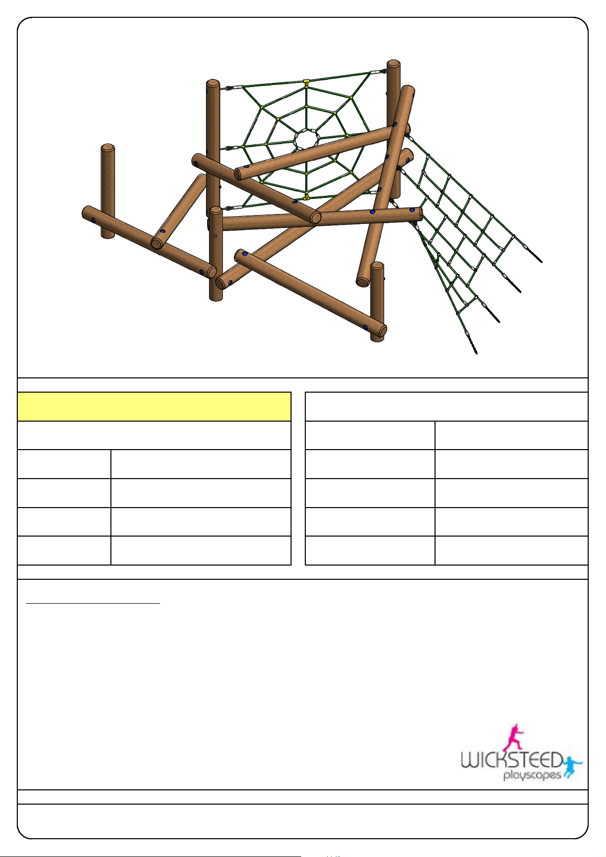
PICUS
TECHNICAL DATA
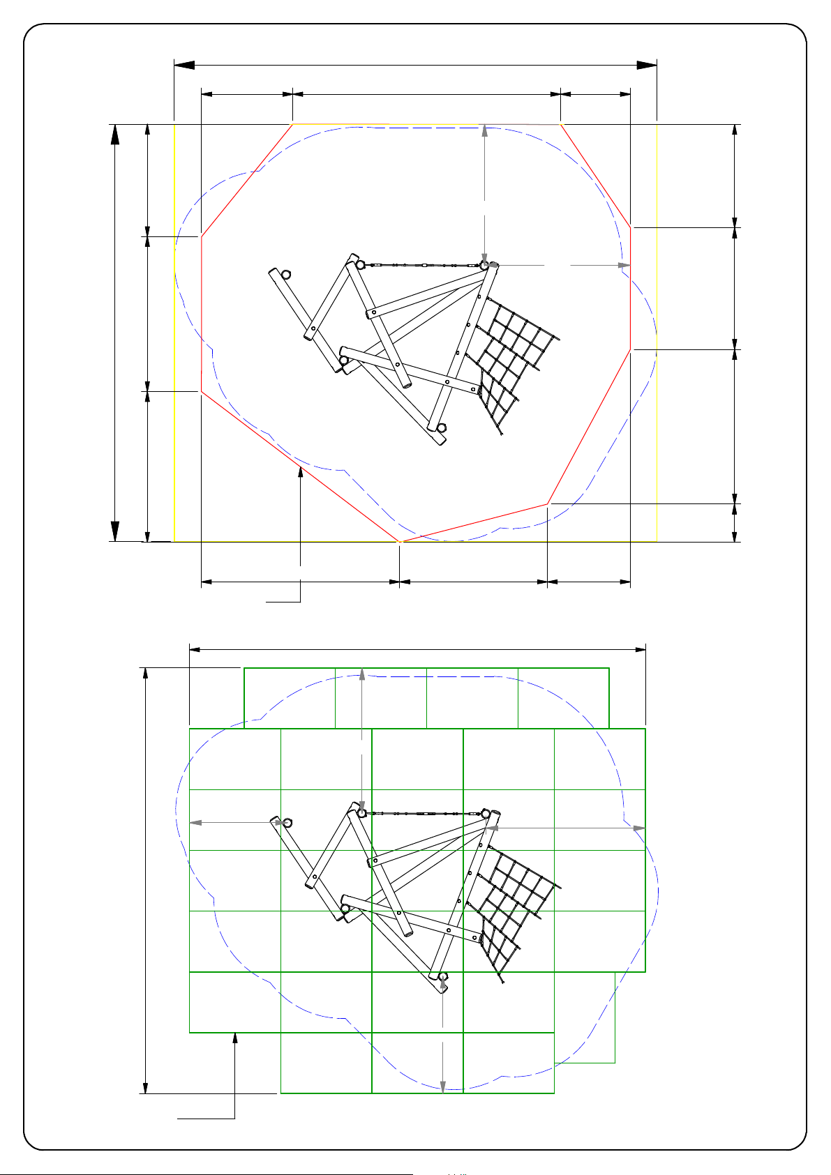
MINIMUM SPACE REQUIRED
SUPERVISED PLAY
EQUIPMENT TYPE
LARGEST PART
HEAVIEST PART
PROD. CODE
SIZE
FFH
AGE RANGE
PICK UP STICKS 'FOUR'
PICUS4
L:4.78M X W:3.12 X H:1.90
1850MM
3 - 7 YEARS OLD
INSTALLATION DETAILS
1. READ INSTALLATION INSTRUCTIONS THOROUGHLY BEFORE COMMENCING INSTALLATION OF UNIT
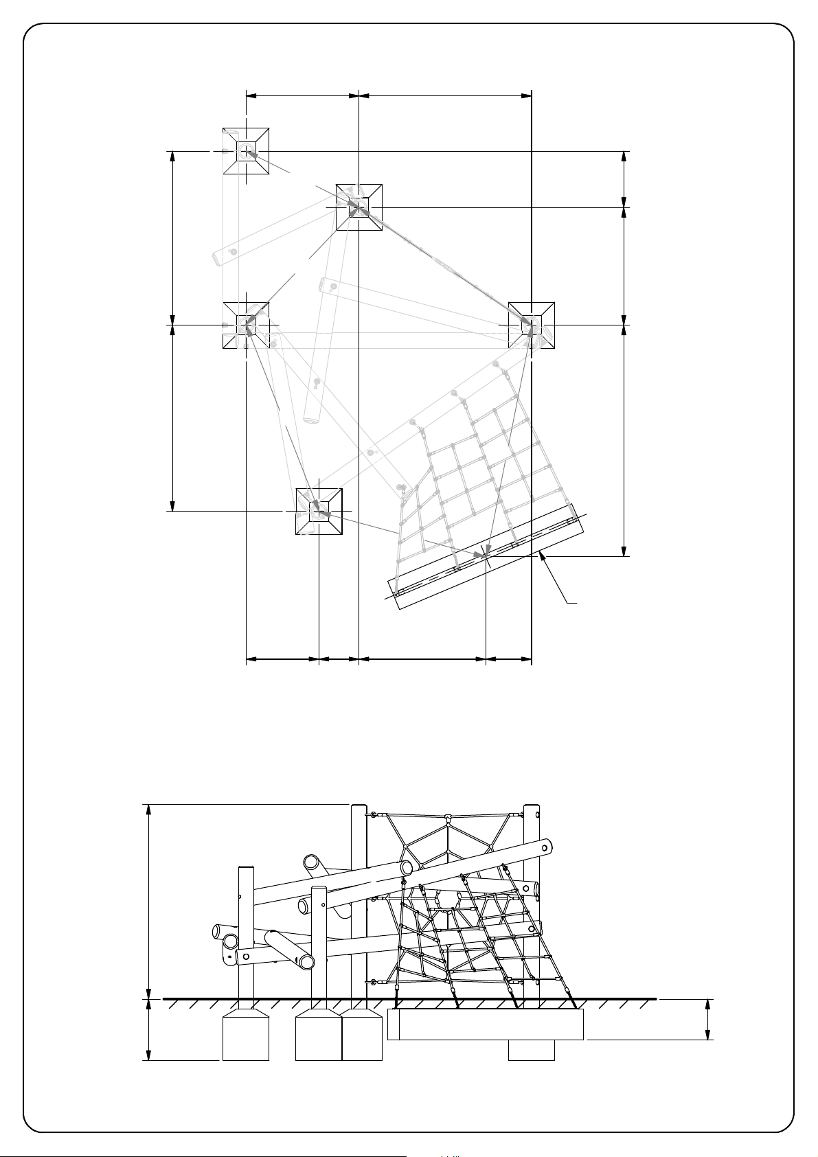
2. EXCAVATE FOUNDATIONS USING THE DETAIL AS SHOWN ON PAGE 2 OF THIS DOCUMENT
3. ENSURE TO CHECK AND TIGHTEN ALL FIXINGS USING PROTECTIVE CAPS WHERE NECESSARY
4. BACKFILL FOUNDATIONS WITH CUBIC M CONCRETE ALLOWING TO SET FOR 48 HOURS
5. REMOVE ALL ASSEMBLY AIDS BEFORE THE EQUIPMENT IS USED
0.12
7.94M X 6.86M
RECOMMENDED
LOW LEVEL
3.00M X 0.15M DIA (004/005 POST)
32KG (004/005 POST)
THIS PRODUCT CONFORMS WITH BS EN1176- :20081
Wicksteed Leisure Ltd, Digby Street, Kettering, Northants NN16 8YJ Tel: 01536 517028 Fax: 01536 410633
No part of this document may b e copied or used without the express written permission of WICKS TEED LEISURE LTD (c) 2016
www.wicksteed.co.uk E:[email protected]
Version: B
Date:
19/10/16
PAGE OF 13PAGE OF 2
Page 2
1102 1685
9
1231
9
9
6
1
1593
0
2
8
1
1954
2040
2304
4
5
0
5
1
1
0
6
2
2
711
FOUNDATIONS ARE 450 X 450 X 600 UNLESS OTHERWISE SPECIFIED
0
0
9
1
391 1237 448
1687
1950 X 300 X 300
0
0
0
6
0
4
3
Page 3
7935
1500 4400 1145
0
5
8
1
2324
2400
0
5
5
5
2
5
8
6
0
8
4
2
0
0
7
1
0
0
0
2
0
4
5
2
0
3
6
38.7 SQ METRES WETPOUR SURFACING
22.0 LINEAR METRES WETPOUR EDGING
1612
0
0
0
7
3260 2430
7500
2391
1360
2628
32 GRASS SAVER TILES
(1.5M X 1.0M)
1928
PAGE OF 3
3
Page 4
LOW LEVEL
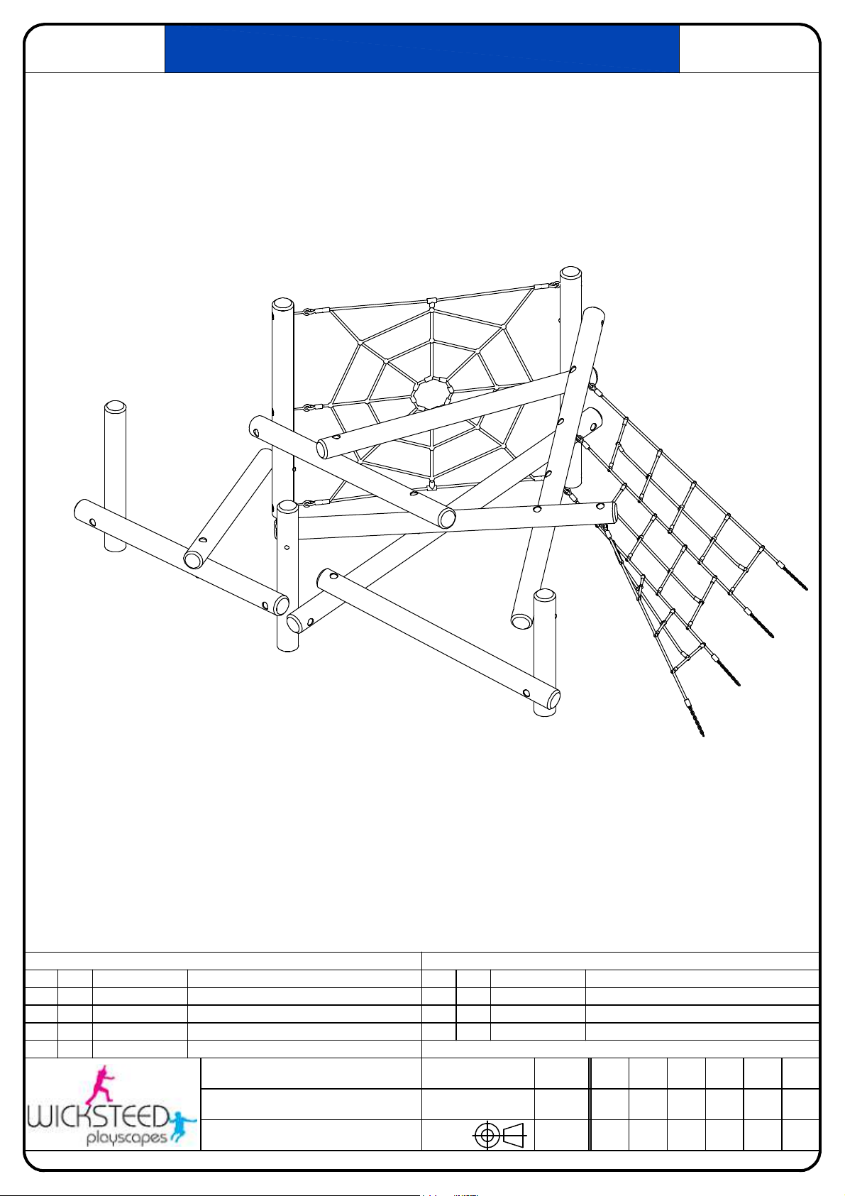
PICK UP STICKS 'FOUR' IN-AY
PICSU
PARTS LIST
ITEM
QTY
PART NUMBER
DESCRIPTION
1 1 FRTB00548 PICK UP STICKS 'FOUR' TIMBER SET
2 1 FRMS00549 PICK UP STICKS 'FOUR' ROPE SET
3 16 M12X280CB M12 x 280 COACH BOLT
4 26 M12NYLOC M12 NYLOC NUT
Drawing Number:
PICUS4-IN-AY
Drawn By:
AK
Sheet:
Wicksteed Leisure Limited, Digby Street, Kettering, Northamptonshire NN16 8YJ Tel: 01536 517028 Fax: 01536 410633 http://www.wicksteed.co.uk Email:[email protected]
No part of this document may b e copied or used without the express written permission of WI CKSTEED LEISURE LIMITED (c) 2016
6
1
OF
PARTS LIST
ITEM
5
PART NUMBER
QTY
DESCRIPTION
26 M12SSWASH M12 PLAIN WASHER FORM A SS
6 26 PLC480DCAP POLY CAP 48
7 1 FRMT00547 PICK UP STICKS GROUND ANCHOR
PICSU4
Date:
07/04/16
3rd Angle
Projection
Issue:Code:
Issue Date:
Sign:
B
19/10/16
AK
PAGE OF 1
6
Page 5
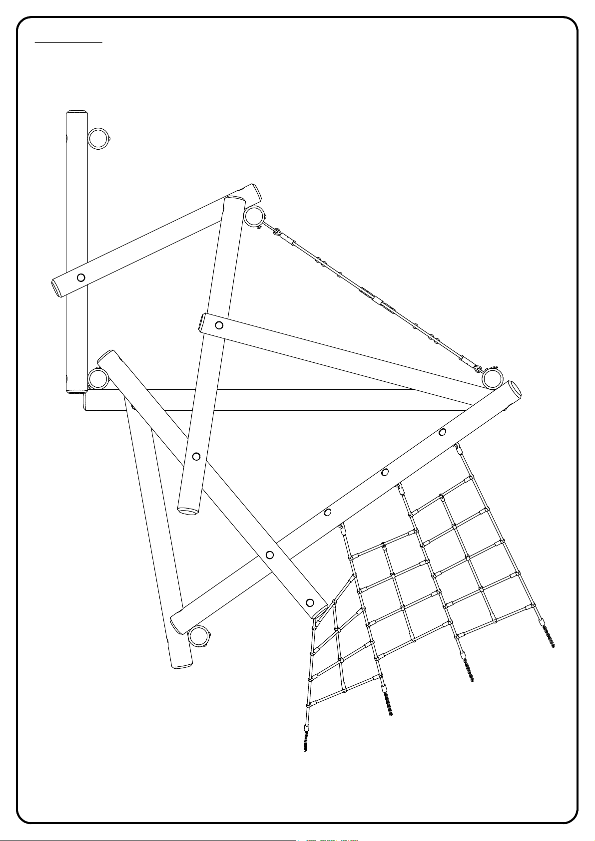
POST LABELS
POST LABELS REFER TO TIMBER SET FRTB00548
009
010
008
001
013
006
011
007
012
003
005
004
002
PAGE OF 2
6
Page 6
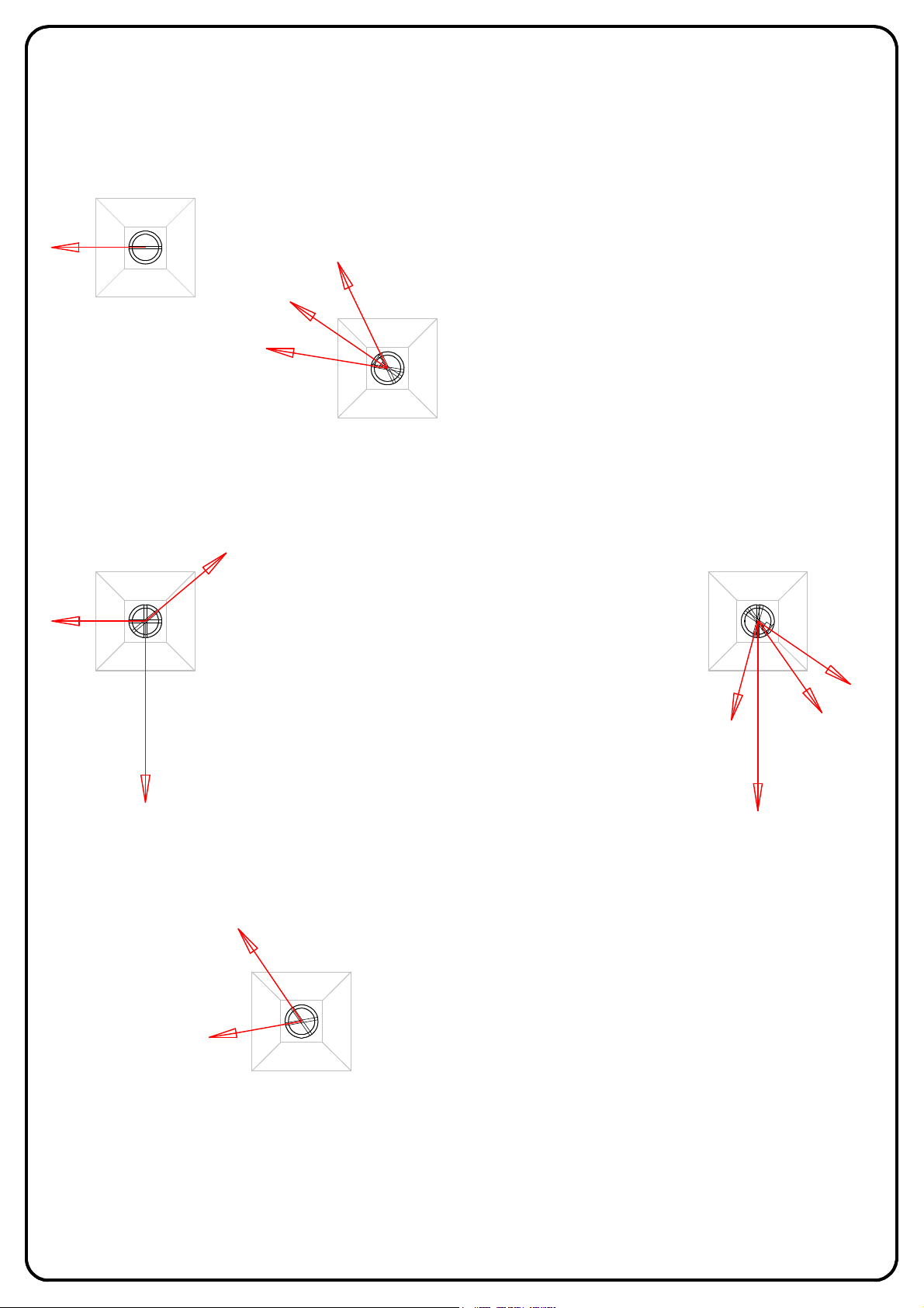
INSTALL THE UPRIGHT POSTS
Excavate the foundation holes as per the Pick Up Sticks 'Four' Spec sheet, and prop and concrete uprights 001, 002, 003, 009, and 010 in the holes.
Ensure the predrilled holes are facing the correct direction as per the illustration below, particularly the counterbore holes (the arrows show the
direction in which the coach bolts will later be secured in). It may be helpful to loosely attach the spider web net to Posts 010 and 003 to achieve the
correct orientation, but do not fully tighten the net's fixings until the unit is fully assembled and concreted in place.
009
COUNTERBORE
HOLE
010
001
002
003
COUNTERBORE
HOLE
PAGE OF 3
6
Page 7
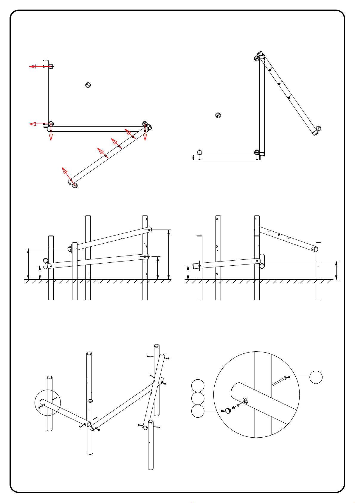
SECURE THE SUPPORTING HORIZONTAL POSTS
Secure Posts 004, 005, and 008 to the upright posts as detailed below in Detail A, ensuring the predrilled holes are facing the correct direction like
before.
008
005
004
005
008
004
PLANS
0
2
9
5
1
4
FRONT ELEVATION
005
004
5
7
4
1
5
8
6
5
1
4
008
5
5
5
SIDE ELEVATION
3
A
5
4
6
DETAIL A
6
PAGE OF 4
Page 8
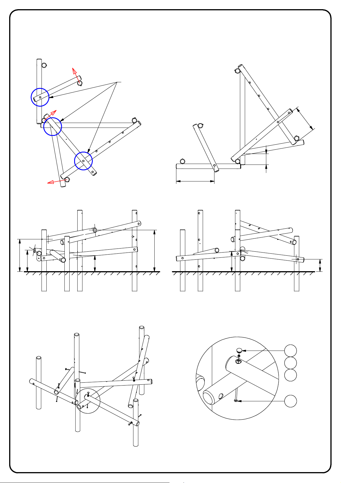
SECURE THE HORIZONTAL POSTS
Secure Posts 006, 007, and 013 to the upright and horizontal posts as detailed below in Detail B, ensuring the predrilled holes are facing the correct
direction like before.
THESE POINTS REQUIRE THE POSTS TO BE POSITIONED,
013
007
006
PRE-DRILLED AND ATTACHED WITH A COACH BOLT
013
1180
007
8
9
5
006
0
8
3
PLAN
013
0
0
0
0
1
6
6
FRONT ELEVATION
007
006
007
0
8
2
1
0
0
5
013
5
2
6
006
0
8
3
SIDE ELEVATION
6
4
5
3
B
DETAIL B
6
PAGE OF 5
Page 9
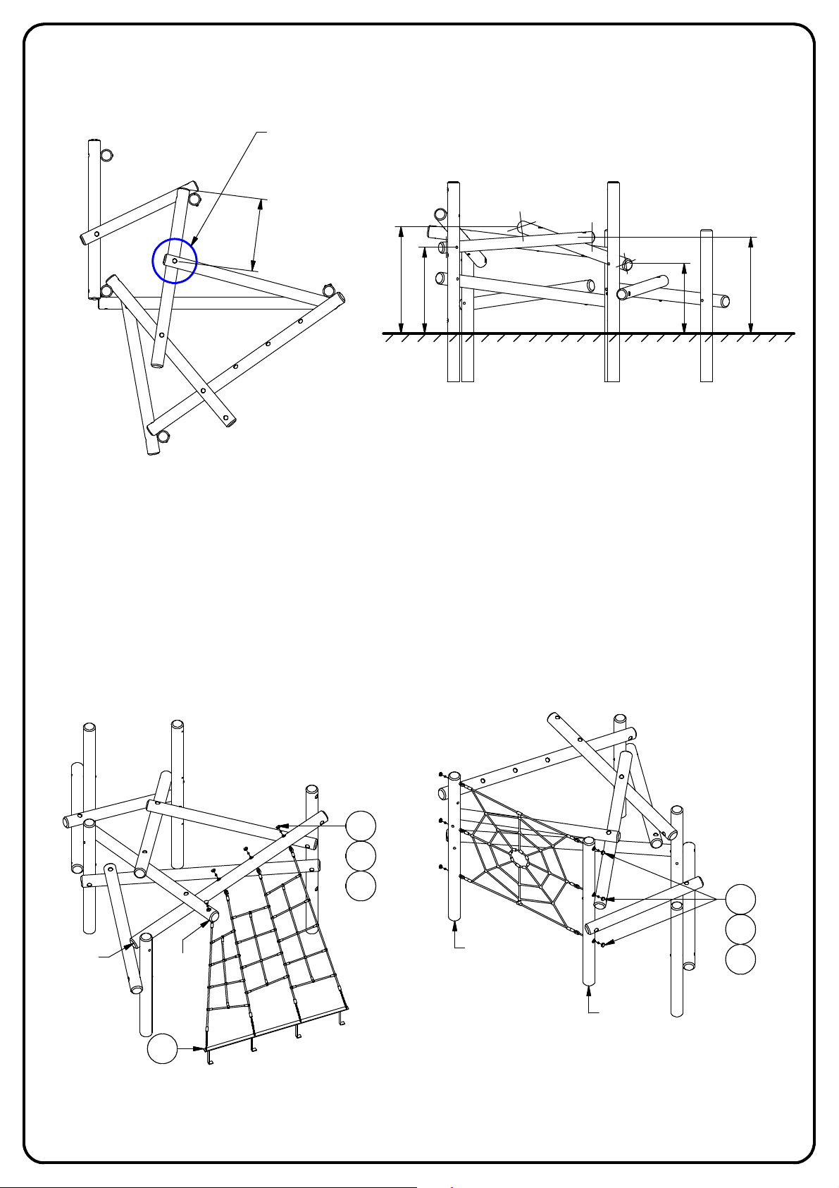
SECURE THE FINAL POSTS
Finally, secure Posts 011 and 012 to the upright and horizontal posts, as detailed on previous pages.
THESE POINTS REQUIRE THE POSTS TO BE POSITIONED,
PRE-DRILLED AND ATTACHED WITH A COACH BOLT
5
6
9
012
011
PLAN
0
4
0
3
8
1
0
1
SIDE ELEVATION
0
8
8
ATTACH SCRAMBLE NET AND SPIDER WEB NET
Loosely secure the scramble net to Posts 004 and 007 using the supplied M12 Nyloc, Washer, and Cap. Attach the Ground Lug (Item 7) and
concrete in place.
If not already secured from earlier to help with post orientation, attach the spider web net in 3 places on Posts 003 and 010 as detailed below.
NOTE: To ensure the ropes are fully tensioned, do not tighten the fixings until the foundations have been left to set for 48 hours.
0
1
2
1
004
6
4
5
6
4
007
003
5
010
7
6
PAGE OF 6
 Loading...