

Wichit Sirichote 8051 User Manual
User’s Manual
8051 Project Board v1.0
Wichit Sirichote, wichit.sirichote@gmail.com
Rev. 1.0, October, 2017

Contents
1. Overview
2. Getting started
3. Using Mikro-c for 8051
4. Example of c programs
Schematic
Bill of Materials (BOM)
1. Overview
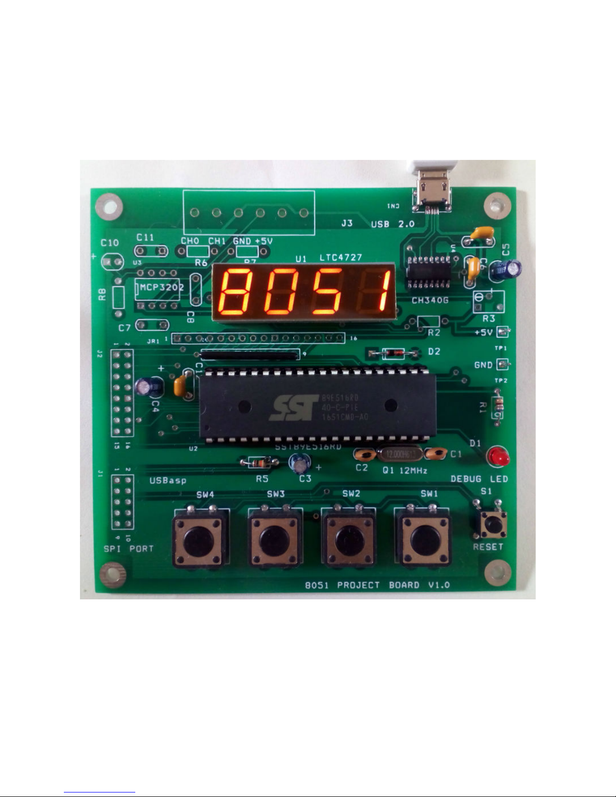
The 8051 project board is designed for teaching how to develop a dedicated microcontroller project
using c coding. The project board is based on the SuperFlash SST89E51RD microcontroller. The
MCU has 64kB code memory with extra 1024 bytes RAM. This memory size is very suitable for c
coding. In addition, the board also provides the 7-segment display, LCD display, keypad, the analog
to digital converter and USB port.
The MCU has bootloader firmware. We can program the code memory without the need of external
programmer. Only the micro USB cable will be needed.
While developing the code with PC, the 8051 project board gets the power from USB port directly.
The micro USB port allows many power sources, e.g., power bank, cheap cell-phone AC adapter.
The example c programs demonstrate how to write c code to control the display, UART, keypad.
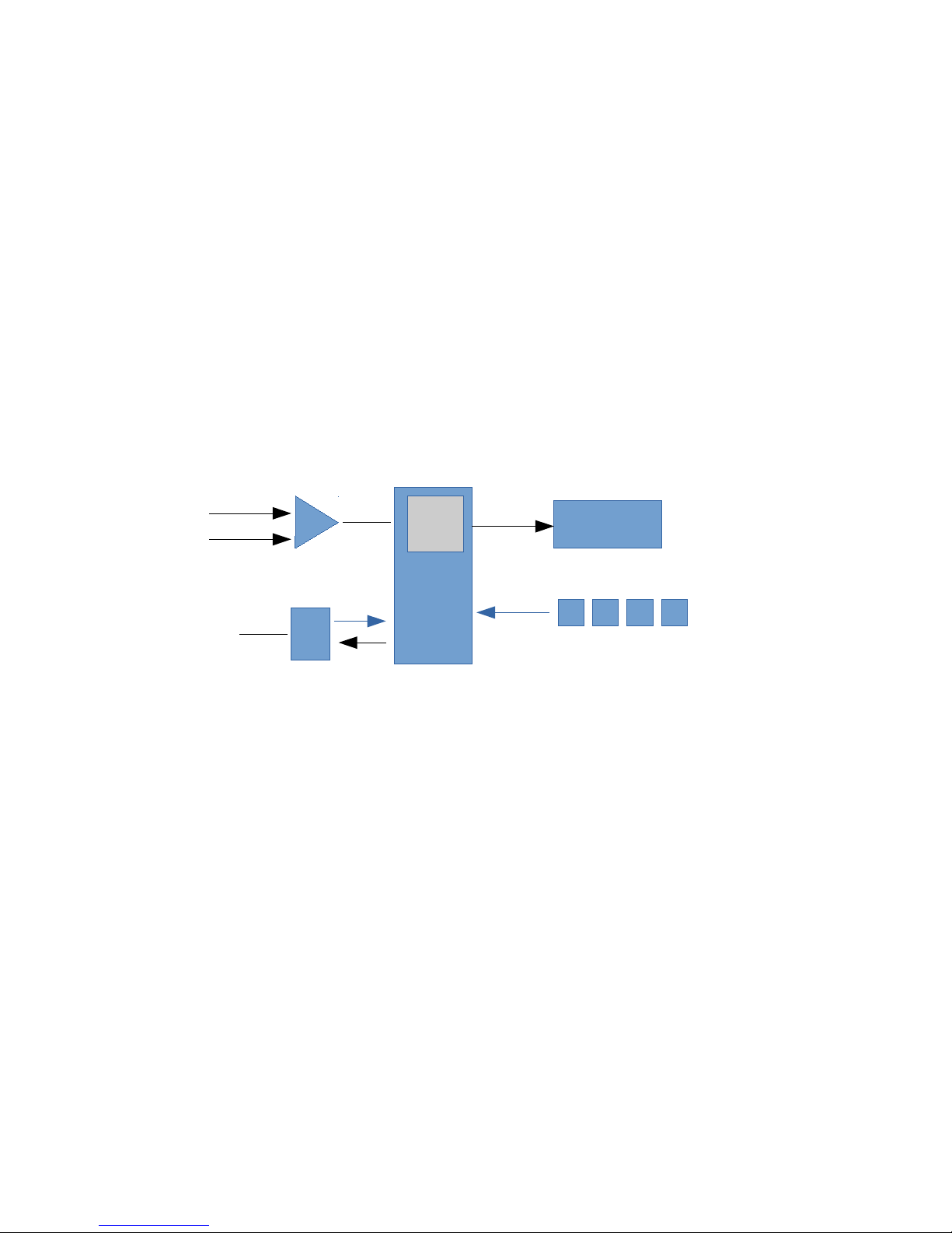
8051
2 channel ADC
SST89E516RD
4-digit 7-segment
display
4 Tact switches
UART
USB
64kB
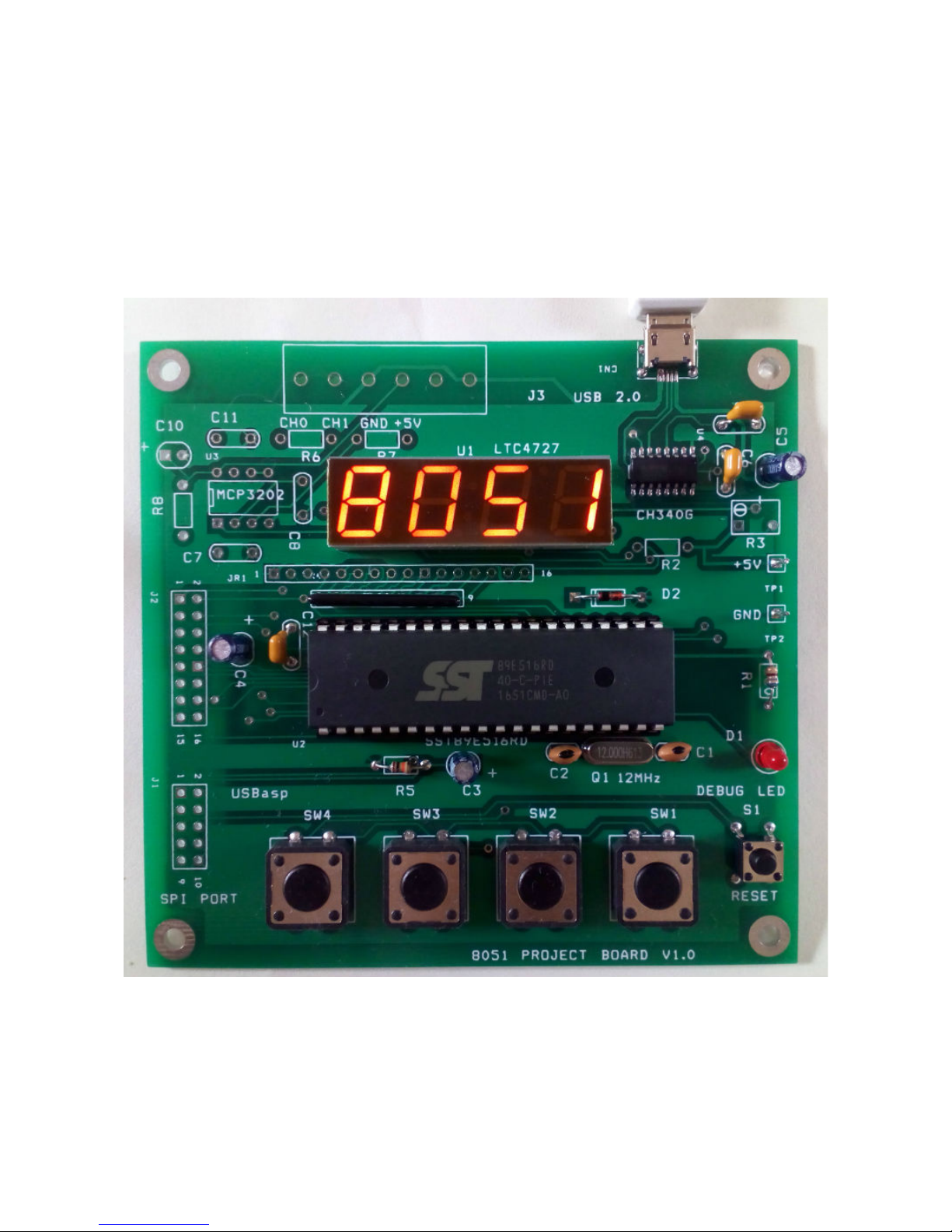
Basic layout
Basic components are:
1. SST89E51RD, 40-pin Microcontroller.
2. 4-digit 7-segment display.
3. USB-UART interface chip, CH340G
4. Tact switch keypad.
5. Micro-USB cable
2. Getting started
Students will need PC, or Notebook computer with USB port. The PC will run c compiler program
and EasyIAP for hex code downloading.
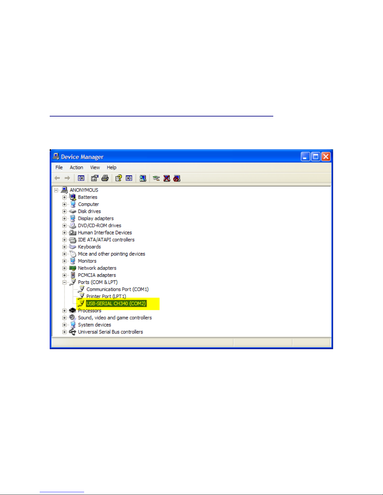
The UART-USB device, CH340G will need the hardware driver.
Step 1 Download and install the driver.
http://www.kswichit.com/Flashflex/images/CH34x_Install_Windows_v3_4.zip
When connect the project board to the PC USB port, the hardware manager will assign the COM
port number automatically.
We can modify the COM port number easily by right click, properties/port settings/advance.
The example was set it to COM2.
We can test communication between the PC and project board by using the EasyIAP program.
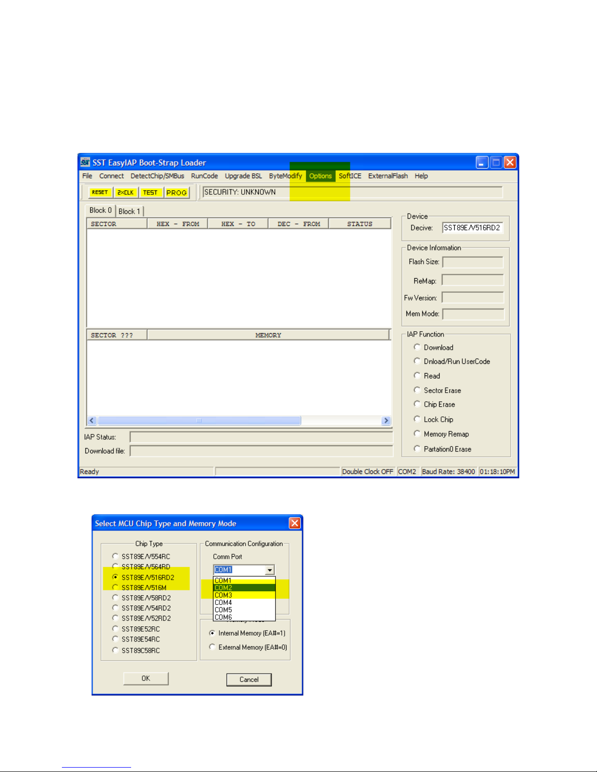
Step 2 Download and install the EasyIAP.
http://www.kswichit.com/Flashflex/EasyIAP%20Rev%206.0.zip
Run the EasyIAP. Click Option.
Select COM2, and SST89E51RD chip.
Press RESET button on the project board.
Then CLICK OK, and release RESET button immediately!
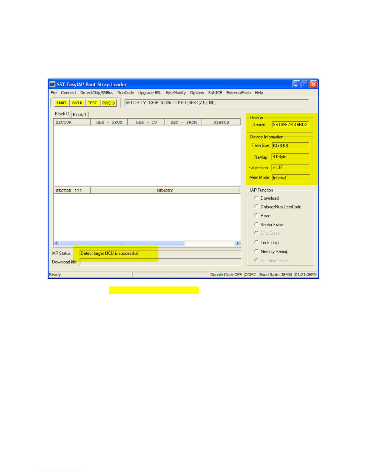
The EasyIAP will connect the project board and display chip information.
The IAP Status shows Detect target MCU is successful!

Click Read right-hand, the code memory will be read. We can see the buffer memory window. It
shows the memory contents in HEX number.
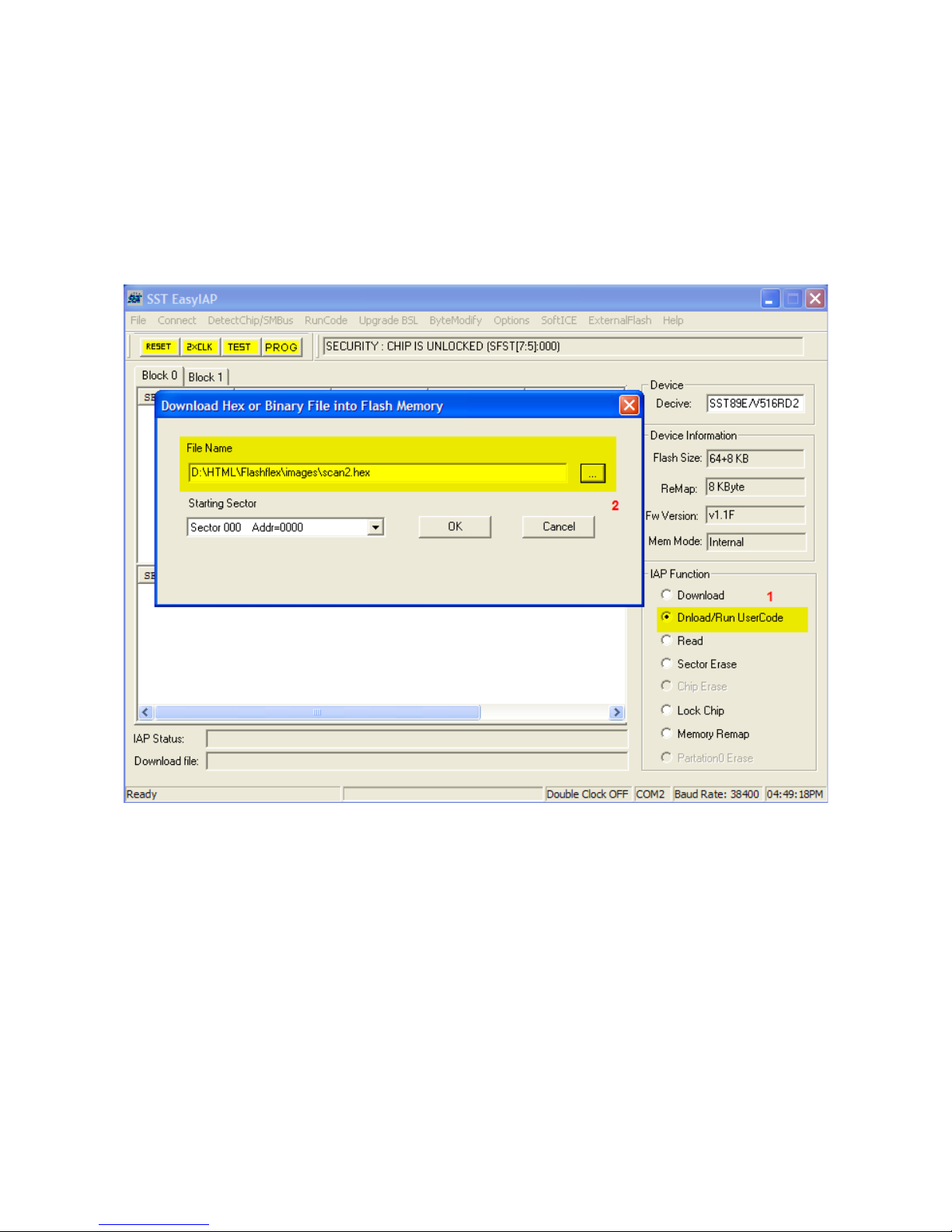
How to write the hex code to the MCU.
Now let us try program the MCU with hex code.
Download the hex file http://www.kswichit.com/Flashflex/images/scan2.hex
We will try using the EasyIAP to program this hex code the MCU.
Step 4 Reconnect the project board with Connect click again.
Click Dnload/Run UserCode 1.
Then Click the hex file 2.
 Loading...