

Page 1
SERVICE MANUAL
Page 2
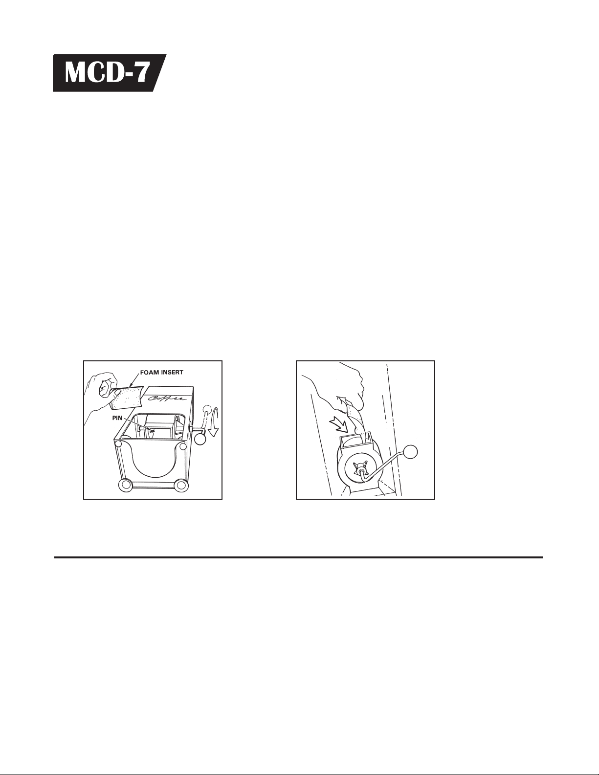
FOAM INSERTS, INSTALLATION
1. Remove lid. Remove bag of inserts.
2. Looking down into the hopper, observe the small nylon pin piercing the left side of the
measuring drum.
3. Now turn unit on its back (see Figure 1.).
4. Using a knife blade or thin screw driver, slide the blade under the head of the pin and pry
out the nylon pin.
5. Pull handle to DOWN position and carefully, place into drum opening, one of the foam inserts (as shown in Figure 2.). Each insert is marked with the quantity, in ounces, that it will
dispense (the smaller the insert, the more coffee dispensed from the unit).
6. Replace nylon pin. Press firmly on the head until it snaps into place.
7. Turn unit upright and fill up the hopper with coffee. The coffee dispenser is now ready for
use.
Figure 1. View of MCD-7, looking
into drum.
Figure 2. View putting foam inserts
in the drum.
OPERATION OF MCD-7
1. Place a coffee filter or a Brew Basket with filter already inserted. Fit it, into the front
opening of the MCD-7.
2. Pulling the handle will dispense the amount of coffee you have selected with the
foam insert. lf you need to change the quantity of ground coffee that is dispensed
(see FOAM INSTERTS INSTALLATION, above) choose a different size of insert.
[ 1 ]
Page 3

Replacing the Handle Return Spring
With use, there may be an occasion where the handle return spring breaks. If this happens,
the handle will no longer automatically lift after being pulled down. The MCD-7 is still usable
simply by lifting up the handle to the top position after pulling down to dispense coffee. This
part can be replaced. Using the illustrated parts breakdown as a guide will help identify the
parts referred to in these instructions. The index numbers in parentheses ( ) will match those
in the parts breakdown.
1. Remove the hopper. The hopper is held in place by a screw (5) and nut (6) on both sides
of the upper of hopper.
2. Remove the round black knob (21) on the handle. Unthread it by twisting counterclockwise.
3. Remove the bottom screw (9) on the side plate
(don't lose the arm stop (7) that it screws into).
Also, on the side plate (8), remove the top screw
and the other stop (7) that it is threaded into.
Take off the side plate.
4. The next step is to remove the drum and shaft
assembly (10). To do this, lay the unit on it's side
with the handle pointing up. Grab the handle (20)
with your right hand. Reach inside the MCD-7
and push against the opposite wall with the flat
of your left hand while with your right hand you
pull up on the handle (figure 3.). The walls are
flexible enough so that with a little tugging you
can dislodge the shaft from the hole in the left
side of the wall.
5. Once free, pull the handle through the hole on
the right side of the MCD-7 (figure 4.) and lift out
the drum and shaft assembly.
6. To get off the broken return spring (17), you will
have to separate the handle from the plastic
drum. The easiest way is to clamp the metal
andle in a vise, grab the drum with both hands
and then just yank off the drum with a firm tug.
7. Take off the collar by loosening the set screw
with an Allen wrench. Take notice of the spring
position.
[ 2 ]
Page 4

9. Replace with a new spring and reverse steps 4 through 7 to reinstall the drum.
10. The drum assembly should be in place with the handle sticking out from the hole on the right
side of the MCD-7. Slide the side plate through the handle and align the screw holes. Rotate the
handle so that it is pointing down. Reaching in from the top, push the end of the spring though
the side hole on the spring retainer (7). Hold on to these while rotating them (put tension on the
spring) to align with the top screw hole. Insert the screw from the outside, though the plate and
into the threaded retainer. Thread the screw into the spring retainer loosely (not tight).
11. Rotate the handle counter clockwise until the stop bar (19) hits the spring retainer. Hold the
handle in this position while replacing the arm stop standoff and screw on the bottom hole of the
plate. Release the handle. The return spring will now have the proper tension to return the handle
when pulled. The travel of the handle is also limited by the stop bar between the standoff and the
spring retainer. Tighten the screw on the spring retainer.
12. Replace the knob on the handle and put the hopper back on.
PARTS LIST
INDEX
NO.
1
2
3
4
5
6
7
8
9
10
11
12
13
14
15
PART
NO.
WC-3606
WC-4504
WC-4502
WC-4002
WC-4004
WC-5408
WC-4505
WC-9185
WC-4312
WC-4806
WC-3207
WC-3601
WC-4311
WC-3400
WC-4805
DESCRIPTION
HEAT GUARD MCD-7
SCREW, 8-32x½ SLTD HEX WSHR HD
SCREW, 8-32x3/8 PAN HEAD
NUT, 8-32 ACORN BRNZ ANTIQUE STEEL
STOP, ARM MCD-7
PLATE, SIDE MCD-7
SCREW, 8-32x½ PAN HEAD PHILLIP
WASHER, E' RING SUPPORT
BEARING, 3/8" FLANGED
PIN, CANOE (10 PER PKG.)
SHAFT, DRUM MCD-7
DRUM ASSY W/SHAFT & RING,MCD-7
SCREW, 3/8” COLLAR W/SET
SPRING, RETURN
PIN, 5/32 x 3/4" ROLL
INDEX
NO.
16
17
18
19
20
21
22
23
24
25
26
27
28
29
PART
NO.
WC-4318
WC-3206
WC-3204
WC-3502
WC-3501
WC-3614
WC-3622
WC-3623
WC-3624
WC-3625
WC-3626
WC-3627
WC-3628
WC-3629
DESCRIPTION
STOP BAR, 1/4" ALUMINUM
PULL ARM, STAINLESS STEEL
KNOB, PULL ARM BALL
LEG, 8-32 STUD SCREW BUMPER
CUP, 8-32 STUD VACUUM (MCD-7)
DRUM INSERTS, FOAM (SET OF 8)
INSERT, 1-¼ oz FOAM (MCD-7)
INSERT, 1-½ oz FOAM (MCD-7)
INSERT, 1-¾ oz FOAM (MCD-7)
INSERT, 2 oz FOAM (MCD-7)
INSERT, 1-¼ oz FOAM (MCD-7)
INSERT, 2-½ oz FOAM (MCD-7)
INSERT, 2-¾ oz FOAM (MCD-7)
INSERT, 3 oz FOAM (MCD-7)
[ 3 ]
Page 5

[ 4 ]
Page 6

Product Warranty Information
The Wilbur Curtis Company certifies that its products are free from defects in material and workmanship under normal
use. The following limited warranties and conditions apply:
3 Years, Parts and Labor, from Original Date of Purchase on digital control boards.
2 Years, Parts, from Original Date of Purchase on all other electrical components, fittings and tubing.
1 Year, Labor, from Original Date of Purchase on all electrical components, fittings and tubing.
Additionally, the Wilbur Curtis Company warrants its Grinding Burrs for Forty (40) months from date of purchase or 40,000 pounds
of coffee, whichever comes first. Stainless Steel components are warranted for two (2) years from date of purchase against leaking
or pitting and replacement parts are warranted for ninety (90) days from date of purchase or for the remainder of the limited warranty
period of the equipment in which the component is installed.
All in-warranty service calls must have prior authorization. For Authorization, call the Technical Support Department at 1-800-995-
0417. Effective date of this policy is April 1, 2003.
Additional conditions may apply. Go to www.wilburcurtis.com
CONDITIONS & EXCEPTIONS
The warranty covers original equipment at time of purchase only. The Wilbur Curtis Company, Inc., assumes no responsibility for
substitute replacement parts installed on Curtis equipment that have not been purchased from the
Wilbur Curtis Company, Inc. The Wilbur Curtis Company will not accept any responsibility if the following conditions are not met. The
warranty does not cover and is void under the following circumstances:
1) Improper operation of equipment: The equipment must be used for its designed and intended purpose and function.
2) Improper installation of equipment: This equipment must be installed by a professional technician and must comply with all
local electrical, mechanical and plumbing codes.
3) Improper voltage: Equipment must be installed at the voltage stated on the serial plate supplied with this equipment.
4) Improper water supply: This includes, but is not limited to, excessive or low water pressure, and inadequate or fluctuating
water flow rate.
5) Adjustments and cleaning:
adjustments are the responsibility of the equipment owner. The owner is responsible for proper cleaning and regular
maintenance of this equipment.
6) Damaged in transit: Equipment damaged in transit is the responsibility of the freight company and a claim should be
made with the carrier.
7) Abuse or neglect (including failure to periodically clean or remove lime accumulations):
variation in equipment operation due to excessive lime or local water conditions. The equipment must be maintained accord ing to the manufacturer’s recommendations.
8) Replacement of items subject to normal use and wear:
rings, gaskets, silicone tube, canister assemblies, whipper chambers and plates, mixing bowls, agitation assemblies and
whipper propellers.
9) Repairs and/or Replacements
up under normal use. All labor shall be performed during regular working hours. Overtime charges are the responsibility of
the owner. Charges incurred by delays, waiting time, or operating restrictions that hinder the service technician’s ability to
perform service is the responsibility of the owner of the equipment. This includes institutional and correctional facilities.
The Wilbur Curtis Company will allow up to 100 miles, round trip, per in-warranty service call.
The resetting of safety thermostats and circuit breakers, programming and temperature
are subject to our decision that the workmanship or parts were faulty and the defects showed
to view the full product warranty information.
Manufacturer is not responsible for
This shall include, but is not limited to, light bulbs, shear disks, “0”
RETURN MERCHANDISE AUTHORIZATION:
Technical Support Department prior to performing any repair work or return of this equipment to the factory. All returned equipment must be repackaged properly in the original carton. No units will be accepted if they are damaged in transit due to improper
packaging. NO UNITS OR PARTS WILL BE ACCEPTED WITHOUT A RETURN MERCHANDISE AUTHORIZATION (RMA). RMA
NUMBER MUST BE MARKED ON THE CARTON OR SHIPPING LABEL. All in-warranty service calls must be performed by an
authorized service agent. Call the Wilbur Curtis Technical Support Department to find an agent near you.
All claims under this warranty must be submitted to the Wilbur Curtis Company
1/07 . F-1988 rev A
WILBUR CURTIS CO., INC.
6913 Acco St., Montebello, CA 90640-5403 USA
Phone: 800/421-6150 Fax: 323-837-2410
Technical Support Phone: 800/995-0417 (M-F 5:30A - 4:00P PST) E-Mail: techsupport@wilburcurtis.com
Web Site: www.wilburcurtis.com
ECN 8739 . 1/18/07 @ 9.1
FOR THE LATEST SPECIFICATION INFORMATION GO TO WWW.WILBURCURTIS.COM
 Loading...