

Page 1

10/100M Ethernet
Media Converter
User Manual
Ver: V2.1.2
Page 2

Model: □10/100M standalone □ Chassis
Distance: MM: Multimode SM: Single-mode
□ 0~2km MM □ 0~5km MM
□ 0~20km SM □ 0~40km SM
□ 0~60km SM □ 0~80km SM
□ 0~100km SM □ 0~120km SM
Optical Port:
□ SC □ FC □ ST □ LC
Fiber:
□ Dual Fiber □ Single Fiber
Converter type:
□Inside Power □Outside Power □Module
Wavelength:
□ 850nm □ 1310nm □ 1550nm
Management:
□Yes □ No
Page 3

Contents
Chapter 1 Introduction ............................... 1
1.1 Descriptions ..................................... 1
1.2 Characteristics ................................. 2
1.3 Technical Parameters ...................... 3
Chapter 2 Operation ................................... 5
2.1 Front Panel ....................................... 5
2.1.1 Indicators ................................. 5
2.1.2 Optical Port .............................. 7
2.1.3 Ethernet port (RJ45) ................ 7
Chapter 3 Installation ................................. 8
3.1 Installation ...................................... 11
3.2 Troubleshooting ............................. 12
Page 4

Page 5

WI-BRIDGE 10/100M Media Converter User Manual
1
Chapter 1 Introduction
1.1 Descriptions
WI-BRIDGE media converter is designed to
convert 100BASE-FX fiber to 100Base-TX copper
media or vice versa.
It is primarily designed for
large, higher speed/ bandwidth demanding work
groups that require expansion of the Ethernet
network. It can extend the conventional 10M
Ethernet or 10/100 fast Ethernet to 2km-120km
via the fast Ethernet fiber optical line.
It is high-performance, cost effective and flexible
solutions for a wide range of applications in the
field of broadband WAN established by data
network operators. It can be inserted into
rack-mount chassis or inserted into standalone
shell.
Page 6

WI-BRIDGE 10/100M Media Converter User Manual
2
The user manual introduces Media Converter
characteristic, function, use and maintenance. Please
read the user manual carefully before installation.
1.2 Characteristics
Supports SNMP management (only for
management device)
Selectable optical link-loss alarm
Selectable four transmitting modes
Comply with IEEE 802.3µ 100BASE-FX/TX,
IEEE802.3 10BASE-T, Standard
Comply with IEEE 802.1Q VLAN TAG,
Spanning Tree standard
Supports 10/100M, full/half duplex auto-
negotiation
Supports auto MDI/MDIX crossover
Supports transmission distance up to 120km
Same card on rack mounted and desktop
Supports over-sized packets up to 1600Bytes
Supports hot-swappable
Page 7

WI-BRIDGE 10/100M Media Converter User Manual
3
1.3 Technical Parameters
Power
supply
110VAC or 220VAC
+24VDC or -48VDC
Operation
Temp.
0℃~+65℃(Business Class)
-30℃~+85℃(Industry Class)
Storage
Temp
-20℃~+90℃
Relative
Humidity
5%~90%(non-condensation)
Outline
size
94mm×70mm×25mm(Power outside)
140mm×110mm×30mm(Power inside)
157mm×128mm×31mm(Socket Card)
Optical Parameters
Multimode
Fiber 62.5/125, 50/125,100/140µm
Output
optical
power
-20~-14dBm
Receiving
sensitivity
<-31dB
Distance 0~2km or 0~5km
Connector SC, ST, FC,LC
Page 8

WI-BRIDGE 10/100M Media Converter User Manual
4
Wavelength 850nm/1310nm
Singlemode
Fiber 9/125,8.3/125,8.7/125or 10/125µm
Distance 0~20km 0~40km 0~60km
Output
optical
power
-12~-8dBm -8~-3dBm -3~ 0dBm
Receiving
sensitivity
< -37dBm < -37dBm < -38dBm
Connector SC, ST, FC
Wavelength 1310nm
Distance 0~80km 0~120km
Output
optical
power
-3~ 1dBm -3~ 2dBm
Receiving
sensitivity
< -38dBm < -38dBm
Connector SC, ST, FC,LC
Wavelength 1550nm(DFB)
when less than 15km, use attenuator
Page 9
WI-BRIDGE 10/100M Media Converter User Manual
5
FPL
FRX
TRX
FDX
PWR
10/100
Chapter 2 Operation
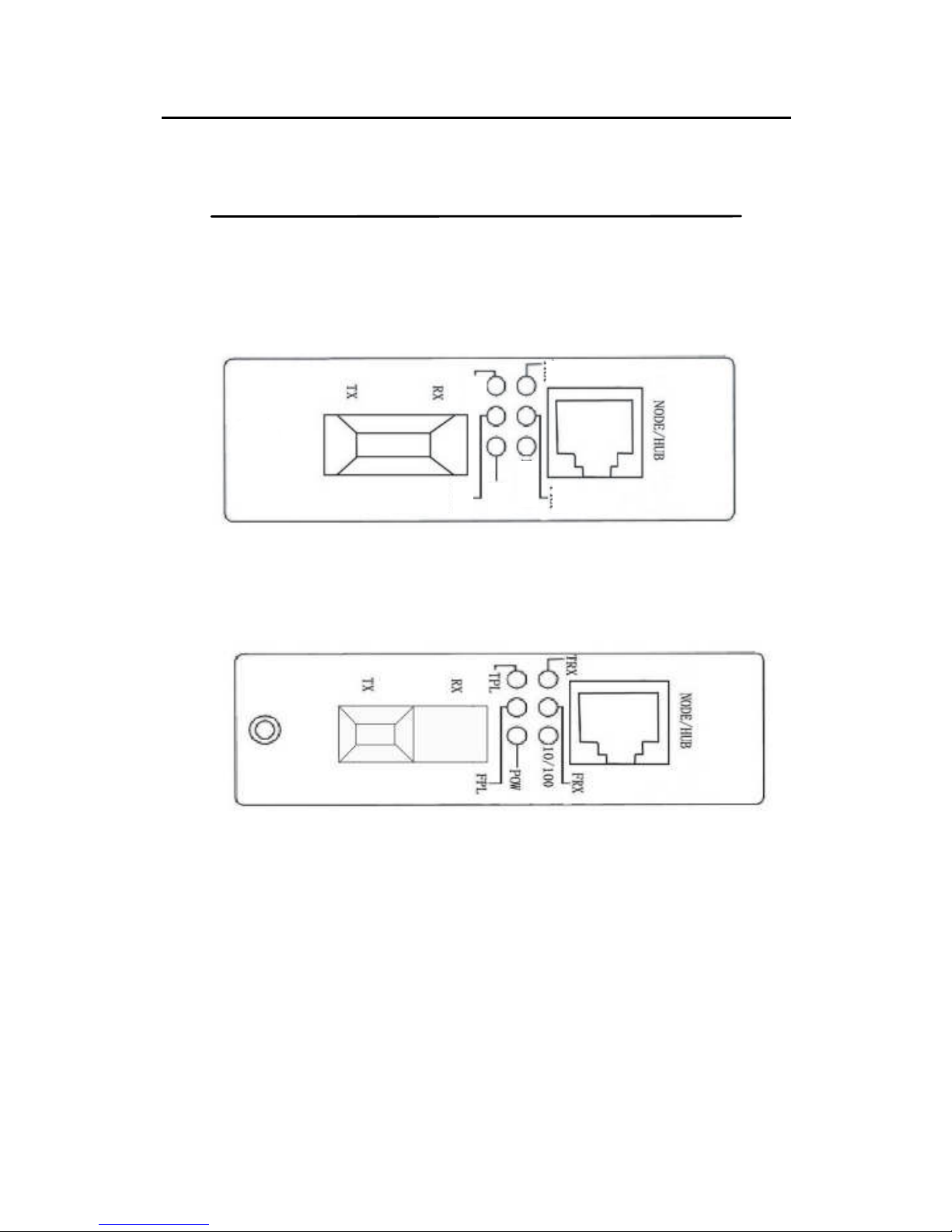
2.1 Stand-alone Converter
Fig 1. Front panel of stand-alone
Fig 2. Front panel of stand-alone(
Single Fiber
)
Page 10

WI-BRIDGE 10/100M Media Converter User Manual
6
2.1.1 Indicators
Six indicators in the front panel of the converter:
Name Definition Specification
PWR
Indicator of
power supply
ON when the power supply is
turned on and in normal
working status
FRX
optical
interface status
indicator
Bright when optic fiber cable
is connected well, but no
data transmission
Blinking when receiving data
TRX
Ethernet
interface status
indicator
Bright when twisted pair is
connected well, but no data
transmission
Blinking, when receiving data
10/100 rate indicator
ON, 100M
OFF, 10M
FPL
Optical
interface signal
detect indicator
ON, when detects the optical
signal
OFF, when no optical signal
detects
FDX
Ethernet
interface mode
indicator
ON, Full duplex
OFF, Half duplex
Page 11

WI-BRIDGE 10/100M Media Converter User Manual
7
2.1.2 Optical Port
RX: Optical signal output
TX: Optical signal input.
2.1.3 Ethernet port (RJ45)
Supports auto MDI/MDIX crossover, the pin definition
of RJ-45:
Pin1 TX+ Output +
Pin2 TX- Output -
Pin3 RX+ Input +
Pin4 NC Not connect
Pin5 NC Not connect
Pin6 RX- Input -
Pin7 NC Not connect
Pin8 NC Not connect
NOTE:
Keeping SW1 default settings is suggested.
Page 12
WI-BRIDGE 10/100M Media Converter User Manual
8
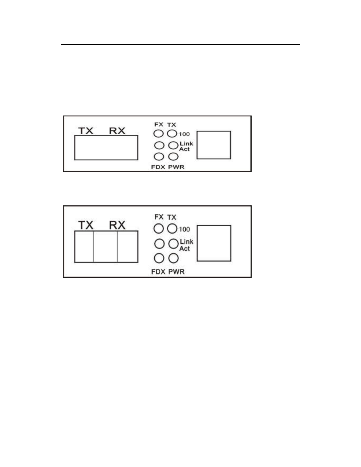
Stand-alone Converter
(((( Internal
power or External power ))))
Fig3. Front panel of stand-alone(
Dual Fiber)
Fig 4. Front panel of stand-alone(
Single Fiber
)
Page 13

WI-BRIDGE 10/100M Media Converter User Manual
9
Name
Definition
Specification
10/100
M
rate
indicator
ON, 100M
OFF, 10M
FX
Optical
interface
signal
detect
indicator
ON, when detects the
optical signal
OFF, when no optical
signal detects
TPLNK/
ACT
Ethernet
interface
status
indicator
Bright when twisted pair is
connected well, but no
data transmission
Blinking, when receiving
data
FXLNK/
ACT
optical
interface
status
indicator
Bright when twisted pair is
connected well, but no
data transmission
Blinking when receiving
data
PWR
Indicator
of power
supply
ON when the power supply
is turned on and in normal
working status
Page 14
WI-BRIDGE 10/100M Media Converter User Manual
10
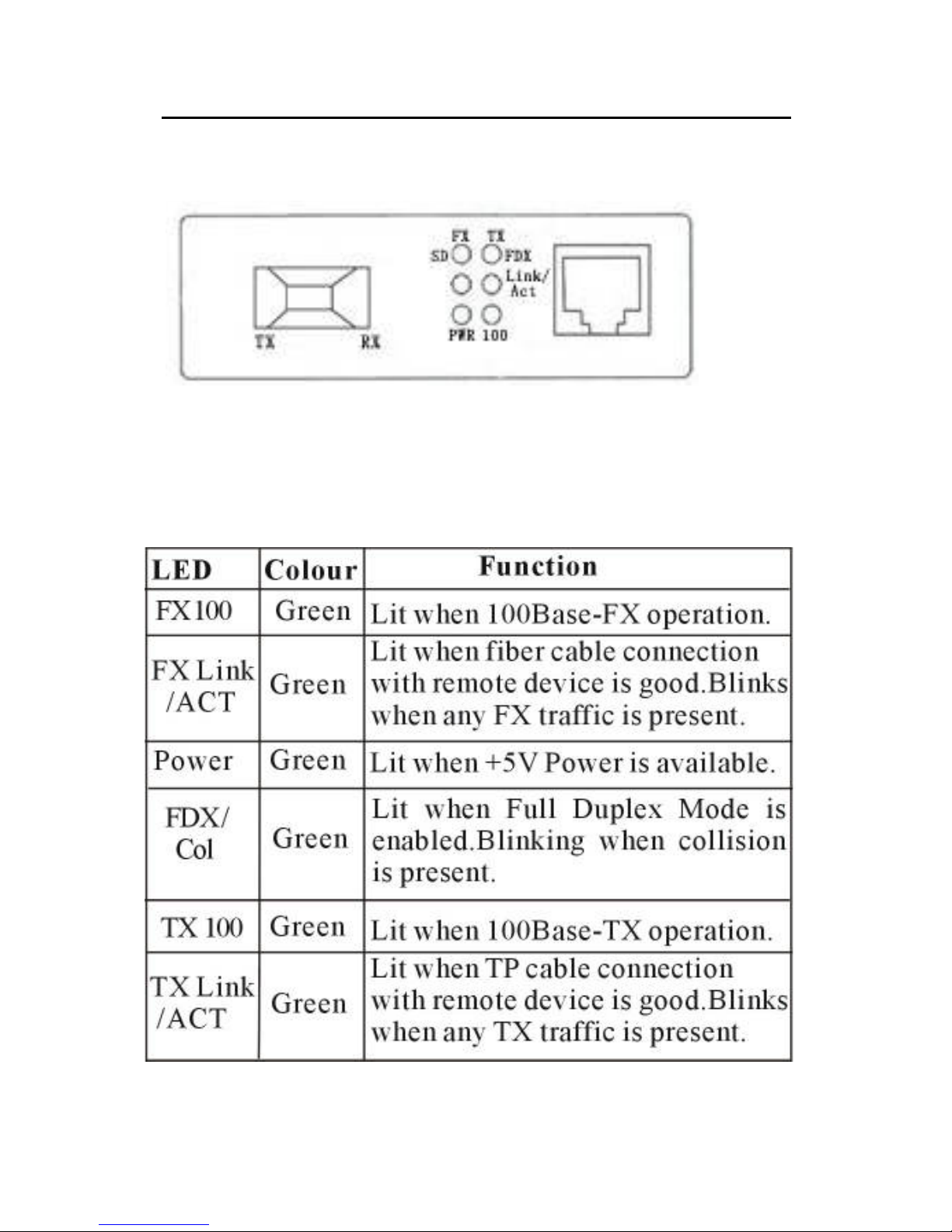
Fig5. Front panel of stand-alone( LC
Dual Fiber)
Page 15

WI-BRIDGE 10/100M Media Converter User Manual
11
Chapter 3 Installation
3.1 Installation
1) After you received the devices, firstly you should
check whether the packing is well, otherwise,
please contact with our company or the local
agent in time so as to solve the problem.
2) Turn on the power supply of the converter.
3) Connect local RX to remote TX via optical fiber,
when local FPL indicator should be bright. And
connect local TX to remote RX, when both local
and remote FRX, FPL indicators should be
bright. If they are single-fiber converters,
connect the optical fiber, and it is OK.
4) Turn on the power supply of the connected
Ethernet devices.
5) Installation is completed.
NOTE:
Page 16

WI-BRIDGE 10/100M Media Converter User Manual
12
Single-fiber bi-directional Media Converter has
two types:
Type A: Transmitting wavelength 1310nm,
receiving wavelength 1550nm.
Type B: Transmitting wavelength 1550nm,
receiving wavelength 1310nm.
Type A and Type B must be used in pair (i.e. if one
end is Type A, then the other end must be Type B)
3.2 Troubleshooting
Failur
e
Reaso
ns
Check
Troubleshooti
ng
POW
OFF
Power
supply
※Check whether
there is power
input.
※Check whether the
power switch is
turned on
※Examine the
external power
supply or turn
on the power
switch
FPL Optical ※Check whether the ※Examine the
Page 17

WI-BRIDGE 10/100M Media Converter User Manual
13
OFF port
fault
fiber link is broken
※Check whether the
optical
consumption is
over-size
※Check whether the
connection is
correct
fiber link
※Correct the
connection
TRX
OFF
TP port
fault
※Check whether the
UTP is broken
※Check whether the
connection type is
matched
※Check whether
the rate is matched
※Examine the
UTP
※Correct the
rate
Page 18
WI-BRIDGE 10/100M Media Converter User Manual
14
Chapter 4 Chassis
(
((
(16slots
、
、、
、
14slots)
))
)
4.1.
..
. Introduction:
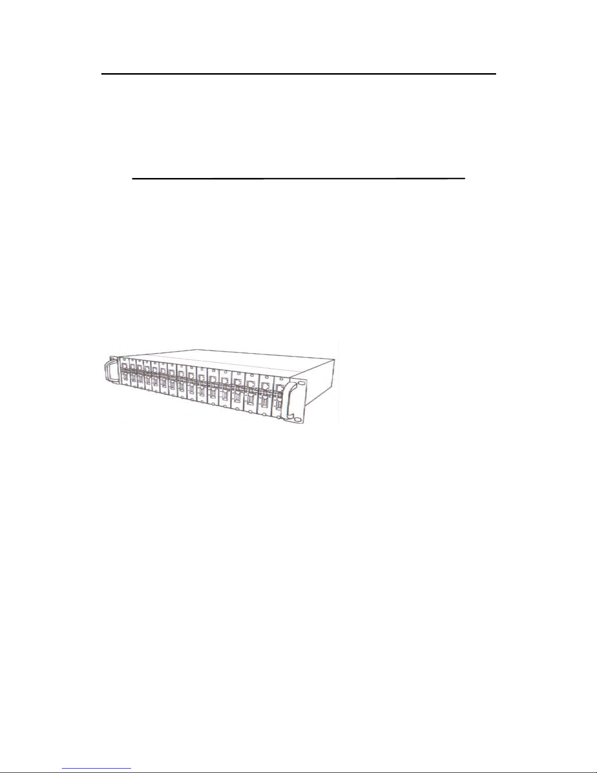
4.1.1product structure
4.1.2 Descriptions
Media converter rack mount chassis is designed to
a standard 19’ 2U rack with centralized
management, centralized power media converter
systems. Rack is equipped with main power; can
be inserted 16 slots media converter cards and
one management card (management option) each
module can be used independently,. It can be
Page 19

WI-BRIDGE 10/100M Media Converter User Manual
15
inserted 100Mbps and Gigabit media converter
cards and single multi-mode converter cards, and
supports hot swap. The chassis using
communication isolation system to make the
system power and transceiver modules completely
separate, to ensure all system reliability.
19’ 2U 14-slot chassis can be inserted 100Mbps,
Gigabit media converter with external power
structure and single multi-mode converter, and
supports hot swap.
4.2Features and Specifications
4.2.1 Key Features
2U19-inch standard rack, can be directly
installed in the chassis, to facilitate unified
management and maintenance;
Fiber media converter module support
hot-swappable ;
MDI/MDIX crossover at electrical port
Page 20

WI-BRIDGE 10/100M Media Converter User Manual
16
16 module slots, network 16 can be inserted
and non-network transceiver module, network
module slot in the chassis rear panel;
Network management network management
module and optical transceiver modules
support Ethernet ports are auto MDI-MDIX,
which automatically identify parallel or
crossover cable;
Intelligent power with full real-time monitoring
(display, alarm, automatic recovery), modular
power supply design, easy maintenance, good
shielding to prevent electromagnetic signals
generated by the power supply module groups
the normal operation of interference;
Network management interface to monitor the
network fiber-optic transceiver modules, power
modules, fan operation;
Dual power backup to ensure the normal
operation of the system chassis, power supply
optional AC220V or DC-48V. 1
Page 21

WI-BRIDGE 10/100M Media Converter User Manual
17
4.2.2 Parameters
Optical transceiver module maximum power:
DC5V/1A
Insert up to 16 rack module and a network
transceiver module (MAX: DC5V/1A)
Fan working power: 12V/300mA
* Working temperature: 0oC~60oC
* Storage temperature: -40oC~70oC
* Humidity: 5%~90%(no-condensing)
Dimension:16 slots 483mm*285mm*90mm
14 slots:483mm*230mm*89mm
4.2.3 Monitoring Network
Management Module Information
Rack power supply, fan work Rack
temperature settings and view
The fiber optic transceiver module Device
Information The fiber optic transceiver port of
physical information The fiber optic transceiver
module settings and work status
Page 22
WI-BRIDGE 10/100M Media Converter User Manual
18
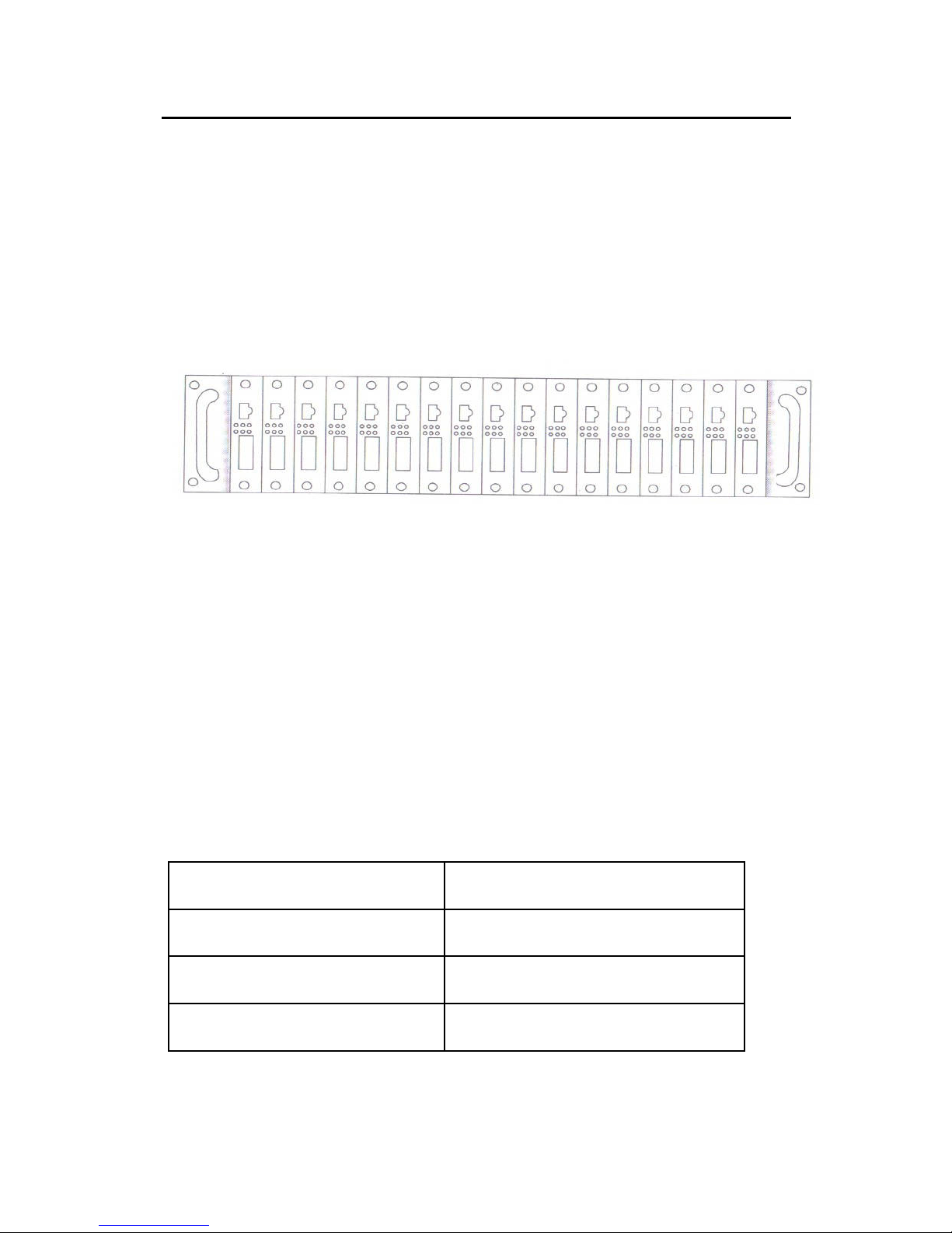
4.3 Installation
4.3.1 Front panel
4.3.2 Power socket:
::
:
AC socket:input AC220V
DC socket:DC-48V
4.3.3 Power Light Indicators
Status Definition
MB ON Power normal
MB OFF Power abnormal
M Reserve
Chart 1:Power Light Indicators for MN、MB
Page 23

WI-BRIDGE 10/100M Media Converter User Manual
19
4.4 use of the environment and the
installation steps
4.4.1 Environment
The use of fiber optic transceivers rack should keep
the ambient temperature 0 ° C-50 ° C, humidity 5%
-90%.
The optical transceiver to place a stable desktop or
rack cabinet, and if possible, avoid the following
environments:
Where direct sunlight or high temperatures
Changes in temperature environment
Dusty or humid environment
Strong electric or magnetic fields
Corrosive gas, flammable gas or chemical fumes
filled the office
4.4.2 Installation Steps
First check the backup power module is plugged in
tight;
Connected AC220V or DC-48V power supply line;
Open the rear panel power switch, power supply can
work properly
Page 24

WI-BRIDGE 10/100M Media Converter User Manual
20
 Loading...