

Wibre 4.0072 Installation Manual
INSTALLATION · MANUAL
4.0072
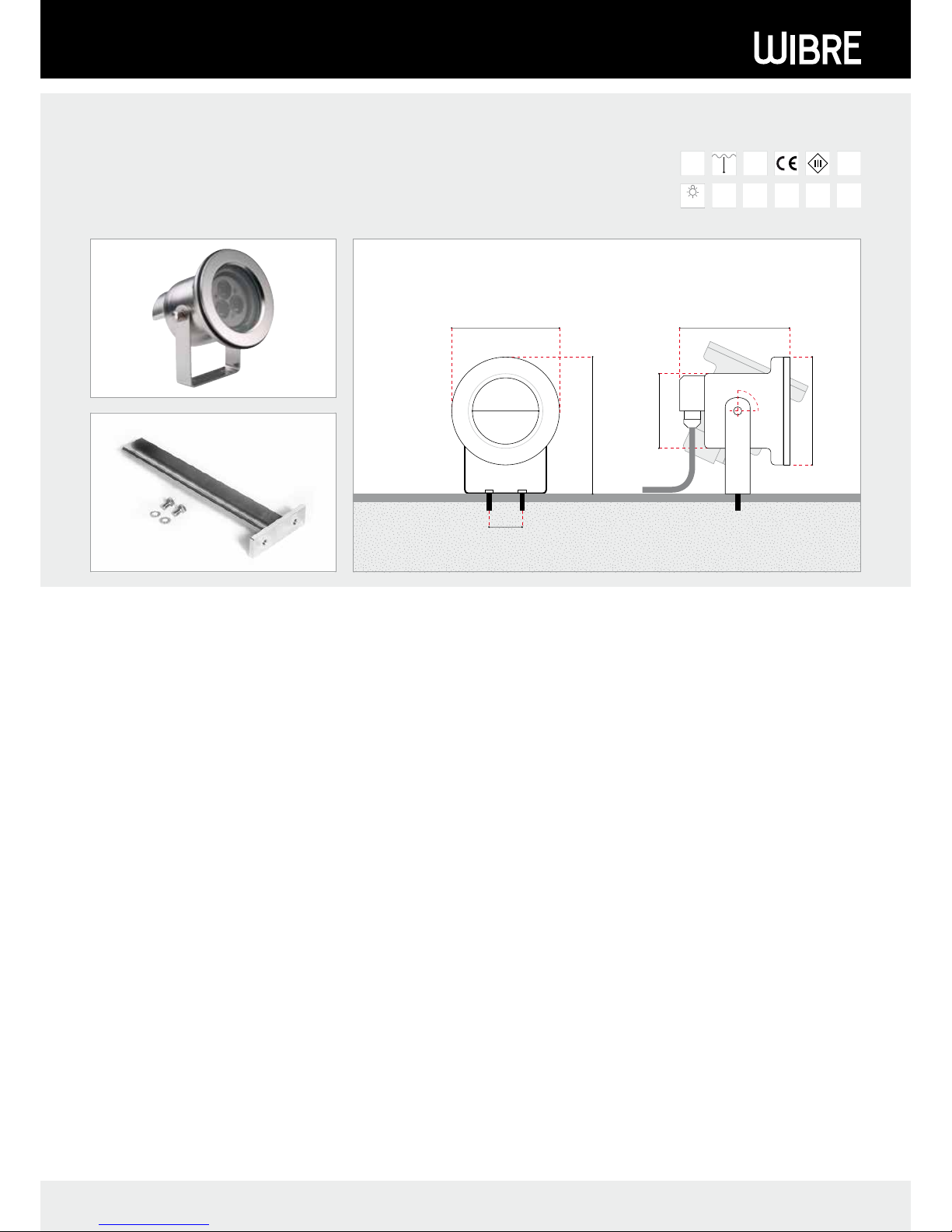
Aufbau-Scheinwerfer aus V4A-Edelstahl
Surface-mounted Spotlight stainless steel 316L
Projecteur en saillie en INOX 316L
1. Anwendung
Aufbauscheinwerfer geeignet für den Einsatz im Außen – und Unterwasserbereich zur Beleuchtung von Springbrunnen, Wasserspielen, Fassaden, Skulpturen oder als allgemeine Effektbeleuchtung.
Sonderkonstruktionen-/anwendungen auf Anfrage.
Bei Einsatz im Unterwasserbereich muss der Scheinwerfer vor
Einfrieren geschützt werden.
Bei der Planung von Beleuchtungsanlagen im Unterwasserbereich
ist zu beachten, dass sich die Beleuchtungsstärke in Abhängigkeit
zur Trübung des Wasser entsprechend verringert. Die angegeben
Scheinwerferdaten beziehen sich immer auf das Medium Luft.
2. Technische Daten/Konstruktion
· Scheinwerfer komplett aus V4A-Edelstahl 1.4571 epoliert
· Schutzart IP68 – Wassertiefe max. 3m
· Einsatz im Aussen- und Unterwasserbereich
· mit 3 POW-LED 350 mA kaltweiss (6000 K), neutralweiss (4500K),
warmweiss (3000 K), farbig; 3 POW-LED RGB 350 mA, NiedervoltHalogen QR-CB51 ES 20 W/35 W/12 V-AC
· Einsatz nur im Unterwasserbereich
· mit 3 POW-LED 700 mA kaltweiss (6000 K), neutralweiss (4500K),
warmweiss (3000 K), farbig; 3 Multichip POW-LED RGB 700 mA,
Niedervolt-Halogen QR-CB51 ES 20 W/35 W/50 W/12 V-AC,
6 POW-LED 700 mA kaltweiss (6000 K)
· rotationsymmetrische Lichtverteilung bei POW LED 10° und 30°
und bei Niedervolt-Halogen 36°
· Kabelverschraubungseinheit mit M16x1,5, PVDF
· Lieferung inklusive Leuchtmittel und 3 m Unterwasserkabel
· Konstantstromnetzteil/RGB Controler/Transformator extern
- Gewicht 1,0 kg
1. Application
Surface mounted spotlights suitable for use in outdoor and underwater
areas for illuminating fountains, water features, facades, sculptures or as
general effect lighting.
Special designs/applications on request.
When used in underwater areas, the spotlight must be protected to
prevent freezing.
When planning lighting systems in underwater areas, it must be noted
that water turbidity reduces illuminance. The spotlight data provided
always refer to air as the medium.
2. Technical data/design
· Spotlight, entirely made of V4A stainless steel 1.4571 EPOL
· Protection class IP68 – Water depth 3 m
· For use in outdoor and underwater environments
· with 3 POW-LED 350 mA cold white (6000 K), neutral white (4500 K),
warm white (3000 K), colored; 3 POW-LED RGB 350 mA,
low voltage halogen QR-CB51 ES 20 W/35 W/12 V-AC
· For use in underwater environments only
· with 3 POW-LED 700 mA cold white (6000 K), neutral white (4500 K),
warm white (3000 K), colored; 3 Multichip POW-LED RGB 700 mA,
low voltage halogen QR-CB51 ES 20 W/35 W/50 W/12 V-AC,
6 POW-LED 700 mA cold white (6000 K)
· Rotationally symmetric light distribution with POW LED 10° and 30°
and for low-voltage halogen 36°
· Screw-type cable fastener with M16x1.5, PVDF
· Supplied with lamp and 3m of underwater cable
· Constant-current power source/RGB controller/transformer external
- Weight: 1,0 kg
1. Application
Projecteur à monter en saillie adapté pour l‘utilisation extérieure et subaquatique pour l‘éclairage de fontaines, de jeux d‘eau, de façades, de sculptures ou
pour créer des effets de lumière.
Constructions/applications spéciales sur demande.
Lors de l‘utilisation subaquatique, le projecteur doit être protégé contre le gel.
Lors de la planification d‘installation d‘éclairage subaquatiques, noter que
l‘intensité d‘éclairage diminue parallèlement à la turbidité de l‘eau.
Les données indiquées pour le projecteur se basent toujours sur une
installation à l‘air.
2. Caractéristiques techniques/Construction
› Projecteur complet en acier inoxydable V4A 1.4571, EPOL
· Indice de protection IP68 – Profondeur d‘immersion jusqu‘à 3m
· Utilisation extérieure et subaquatique
· avec 3 POW-LED 350 mA blanc froid (6000 K), blanc neutre (4500 K),
blanc chaud (3000 K), couleur; 3 POW-LED RVB 350 mA,
halogène basse tension QR-CB51 ES 20 W/35 W/12 V CA
· Utilisation subaquatique uniquement
· avec 3 POW-LED 700 mA blanc froid (6000 K), blanc neutre (4500 K),
blanc chaud (3000 K), couleur; 3 Multichip POW-LED RGB 700 mA,
halogène basse tension QR-CB51 ES 20 W/35W/50 W/12 V CA,
6 POW-LED 700 mA blanc froid (6000 K)
· Diffusion de la lumière à symétrie de rotation de 10° et 30° pour POW LED
et de 36° pour halogène basse tension
· Unité presse-étoupe avec M16x1,5, PVDF
· Ampoule et câbles immergeables de 3 m inclus dans la livraison
· Bloc d‘alimentation en courant continu/contrôleur RVB/transformateur
externe
- Poids: 1,0 kg
WIBRE Elektrogeräte Edmund Breuninger GmbH & Co. KG · Liebigstrasse 9 · 74211 Leingarten/Germany
Telefon: +49 (0) 7131 9053-0 · Telefax: +49 (0) 7131 9053-19 · E-Mail: info@wibre.de
1/4
IP68
3 M
V4A
EDELSTAHL
INKL
KABEL
INKL
EPOL
119,5
9568
95 96,5
65
40
ø 5,5 ø 5,5
90°
9568
96,5
205
90°
INSTALLATION · MANUAL
3. Installation/Montage
Zur Installation sind die nationalen Sicherheitsvorschriften zu
beachten. Es wird keine Haftung für unsachgemäßen Einsatz oder
Montage übernommen. Bei nachträglichen Änderungen an den
Leuchten wird keine Haftung übernommen.
POW-LED Leuchten müssen immer in Reihenschaltung an entsprechenden Konstantstromnetzteilen (siehe Betriebsgeräte) betrieben
werden.
Die Leuchtengehäuse sind nicht zu demontieren, da zum Schutz die
Kabel und POW LED Platine vergossen ist.
Montage des Scheinwerfers ist im Aussen- und Unterwasserbereich
auf verschiedenstem Monatgegrund möglich. Aufbaumonatge
direkt auf Beton, Pflaster, Platten, Holzdielen und in Verbindung mit
Erdspiess 9.0072.20.00 in Erdreich, Kies, Rasenflächen oder Beete
möglich.
Da bei Projekten die Aufbausituationen variieren ist keine allgemein
gültige Montageanleitung möglich. Die Piktogramme verdeutlichen
typische Montagebeispiele.
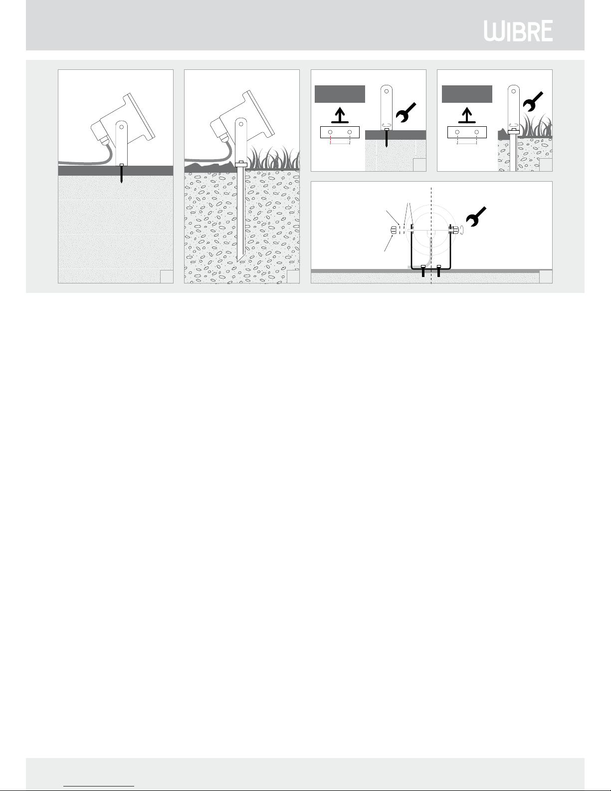
3.1. Aufbaumontage des Scheinwerfers auf festem Untergrund
3.2. Aufbaumontage des Scheinwerfers in Verbindung mit Erdspieß
in losem Untergrund.
Montage
Bei Aufbaumontage des Scheinwerfers auf festem Untergrund wie
z.B. Beton, Steinplatten, Holz und Fassade die seitliche Hutmuttern
öffnen, Unterlegscheibe und Zahnscheibe entfernen und den
Schweinwerfer aus dem Bügel nehmen. Den Bügel zum Objekt
ausrichten und auf Untergrund mit den beiliegenden Edelstahlschrauben befestigen 3.3.
Bei Aufbaumontage des Scheinwerfers in Verbindung mit Erdspieß
in losem Untergrund wie z.B. Erde, Kies die seitlichen Hutmuttern
öffnen, Unterlegscheibe und Zahnscheibe entfernen und den
Schweinwerfer aus dem Bügel nehmen. Den Erdspieß zum Objekt
ausrichten, im Untergrund fixieren und den Bügeln mit den beiliegenden Edelstahlschrauben am Erdspieß befestigen 3.4.
Achtung: Nur werkseitig angeschlossenes Kabel verwenden.
Gewünschte Kabellänge bei Bestellung angeben oder entsprechende
Verbinder mit Vergußmasse zur Kabelverlängerung verwenden
(WIBRE Art.-Nr. 9.9011.02.02; 9.9011.02.03).
Bei erhöhter mechanischer Beanspruchung sollte das Kabel zusätzlich in einem Schutzrohr zur Leuchte verlegt werden.
Einzelanschlussader entsprechend den Vorschriften an den Netzteilen elektrisch anschließen. 3.6.
Die maximale Anzahl der Leuchten sind dem Manual des Netzteiles
zu entnehmen. 3.7.
3. Installation/mounting
When installing, observe the national safety regulations. We are not liable
for any improper use or installation. No liability will be accepted in case of
subsequent modification to the lights.
POW LED lights must always be operated in series with appropriate
constant-current power sources (see operating devices).
The light housings must not be removed, since the cable and POW LED
printed circuit board are sealed for protection.
The spotlight can be mountedin outdoor and underwater areas on a broad
range of surfaces. Surface mounting straight onto concrete, paving, slabs,
wooden floor boards and in conjunction with earth spike 9.0072.20.00 in
soil, gravel, lawns or garden beds.
Since the mounting conditions vary from project to project, no general
installation instructions can be provided. The icons symbolise typical
installation examples.
3.1. Surface mounting of the spotlight on a solid surface
3.2. Surface mounting of the spotlight in conjunction with an earth spike
on a soft surface
Installation
To surface mount the spotlight on a solid surface, such as concrete,
flagstones, wood and facade, open the side cap nuts, remove washer and
serrated washer and take the spotlight out of the bracket. Line up the
bracket with the object and fasten to the surface using the stainless steel
screws supplied 3.3.
To surface mount the spotlight in conjunction with an earth spike on a soft
surface, such as earth or gravel, open the side cap nuts, remove washer and
serrated washer and take the spotlight out of the bracket. Line up the earth
spike with the object, fix into the surface and fasten the bracket to the
earth spike using the stainless steel screws supplied 3.4.
Attention: Use only cable connected at the factory. Specify the
required cable length when ordering or use an appropriate connector and
sealing compound to extend the cable (WIBRE Art. no. 9.9011.02.02;
9.9011.02.03).
In case of increased mechanical load, the cable should also be laid in a
protective tube leading to the light.
Connect individual wires to the power supply according to the
regulations. 3.6.
The maximum number of lights is stated in the power supply manual. 3.7.
3. Installation/Montage
Respecter les prescriptions nationales applicables en matière de sécurité.
Nous déclinons toute responsabilité pour l’utilisation ou le montage non
conforme. De même, nous réfutons toute responsabilité pour les modifications réalisées sur les luminaires.
Pour leur exploitation, les projecteurs à POW-LED doivent toujours être reliés
en série au bloc d‘alimentation en courant continu correspondant (voir blocs
d‘alimentation).
Ne pas démonter les boîtiers de projecteur, étant donné que les câbles et la
platine POW LED sont scellés.
Le montage extérieur et subaquatique du projecteur peut être réalisé sur
différents supports. Montage du projecteur directement sur le béton, les
pavés, les plaques, les lames de bois et en association avec un piquet de terre
9.0072.20.00 dans la terre, le gravier, les espaces verts ou les plates-bandes.
Étant donné que dans les différents projets, les situations d’intégration
varient, nous ne pouvons établir une notice de montage générale. Les
pictogrammes expliquent les exemples de montage type.
3.1. Montage en saillie du projecteur sur un support consolidé
3.2. Montage en saillie du projecteur en association avec un piquet de mise
à la terre sur un support non consolidé
Montage
Lors du montage en saillie du projecteur sur un support consolidé, par ex. le
béton, les plaques de pierre, le bois et les façades, ouvrir les écrous-chapeaux
latéraux, retirer la rondelle et la roue dentée et retirer le projecteur de son
étrier. Orienter l‘étrier vers l‘objet et fixer sur le support à l‘aide des vis en acier
inoxydable 3.3. fournies.
Lors du montage en saillie du projecteur en association avec un piquet
de terre sur un support non consolidé, par ex. la terre, le gravier, ouvrir les
écrous-chapeaux latéraux, retirer la rondelle et la roue dentée et retirer le
projecteur de son étrier. O rienter le piquet de terre vers l‘objet et fixer sur le
support et l‘étrier à l‘aide des vis en acier inoxydable fournies sur le piquet
de terre 3.4.
Attention: utiliser uniquement les câbles raccordés en usine. Indiquer
la longueur de câble souhaitée lors de la commande ou utiliser des
connecteurs adaptés avec une masse de scellement pour rallonger le câble
(n° réf. WIBRE 9.9011.02.02; 9.9011.02.03).
En cas de sollicitation mécanique élevée, le câble vers le luminaire doit être
posé dans une gaine de protection.
Raccorder les différents conducteurs aux blocs d‘alimentation conformément
aux prescriptions. 3.6.
Le nombre maximal de projecteurs est indiqué dans le manuel du bloc
d‘alimentation. 3.7.
2/4
WIBRE Elektrogeräte Edmund Breuninger GmbH & Co. KG · Liebigstrasse 9 · 74211 Leingarten/Germany
Telefon: +49 (0) 7131 9053-0 · Telefax: +49 (0) 7131 9053-19 · E-Mail: info@wibre.de
40
ø 5,5
Object
40
Object
Zahnscheiben
serrated washers
roues dentées
Unterlegscheibe
washer
rondelle
Hutmutter
cap nut
écrous-chapeaux
3.1 3.2
3.3
3.5
3.4
 Loading...