

WiBorne WAP 240 Quick User Manual

WAP & CAP Series
Outdoor W ir eless
AP/Bridge/Mesh/Router/CPE
Quick User Guide
Version 6.30.1
WiBorne, Inc.

2
© Copyright 2005-2017 WiBorne, Inc. All rights reserved.
This product or document is protected by copyright and distributed under licenses restricting its use, copying,
distribution, decryption, decompilation, and reverse engineering. No part of this product or document may be
reproduced in any form by any means without prior written authorization of WiBorne, Inc., or its licensors, if
any.
The information in this document is subject to change without notice. This documentation is provided “as is”
and all express or implied conditions, representations and warranties, including any implied warranty of
merchantability, fitness for a particular purpose or non-infringement, are disclaimed, except to the extent that
such disclaims are held to be legally invalid.

3
Table of Content
Preface...................................................................................................................................................................... 12
Installation Requirements .................................................................................................................................... 12
Packing List ......................................................................................................................................................... 12
CAP-2400 / CAP-5000/N Series ..................................................................................................................... 12
WAP-240 / WAP-500/N Series ........................................................................................................................ 12
WAP-520N ....................................................................................................................................................... 13
System Requirements........................................................................................................................................... 13
Hardware Overview ................................................................................................................................................. 14
Field Installation .................................................................................................................................................. 14
CAP-2400 / CAP-5000 Series ......................................................................................................................... 14
WAP-240 / WAP-500 Series ............................................................................................................................ 15
RJ45 Ethernet Connector System (ECS) ............................................................................................................. 16
Power over Ethernet Unit..................................................................................................................................... 18
Lighten Protector / Surge Protector ..................................................................................................................... 19
Introduction .............................................................................................................................................................. 20
Overview .............................................................................................................................................................. 20
Getting Started ......................................................................................................................................................... 22
Management ......................................................................................................................................................... 22
Password .............................................................................................................................................................. 22
Interfaces .............................................................................................................................................................. 23
Web Based (Browser) Interface ........................................................................................................................... 23
Browser Interface Login S creen .......................................................................................................................... 23
Primary Features and Pages of the Browser Interface (Webbox) ........................................................................ 24
WebFig (Web Browser) Interface ........................................................................................................................ 26
Connecting to WAP/CAP ................................................................................................................................. 27
Interface Overview........................................................................................................................................... 27
Item configuration ............................................................................................................................................ 28
Skins ................................................................................................................................................................. 30
Designing skins ............................................................................................................................................ 30
Skin Example to Configure Wireless Interface->Status Page ...................................................................... 31
Skin design examples ................................................................................................................................... 32
Using skins ................................................................................................................................................... 33
Winbox (Windows GUI) Interface ....................................................................................................................... 33
Primary Features and Pages of the Winbox Interface .......................................................................................... 35
Command Line Interface ..................................................................................................................................... 36
Telnet .................................................................................................................................................................... 37
Console (Serial) Port ............................................................................................................................................ 39
Basic Configuration through Web Browser ............................................................................................................. 41
Quick Setup .......................................................................................................................................................... 41
Web Browser Interface page ................................................................................................................................ 42
Port W eb Configuration ....................................................................................................................................... 42
Port Name Web Configuration ............................................................................................................................. 42
Interface Web Graphing ....................................................................................................................................... 43
System Web Configuration .................................................................................................................................. 43
Firewall Web Configuration ................................................................................................................................. 44
DHCP Server W eb Configuration ........................................................................................................................ 44
Upgrading Firmware through Web Browser ........................................................................................................ 45
Remote Firmware Upgrade .................................................................................................................................. 47

4
Section 5 Basic Configuration through Winbox ...................................................................................................... 50
Configuring an IP address .................................................................................................................................... 50
Configuring the Wireless Card ............................................................................................................................. 51
Configuring Firewall ............................................................................................................................................ 51
Configuring DHCP Server ................................................................................................................................... 53
Configuring Queues ............................................................................................................................................. 55
Introduction ...................................................................................................................................................... 55
Assumptions ..................................................................................................................................................... 55
Packets marking - configuration ...................................................................................................................... 56
New queue type creating .................................................................................................................................. 57
The main queue creating .................................................................................................................................. 58
Adding proper queues ...................................................................................................................................... 58
Optimization .................................................................................................................................................... 59
Per Connection Queue (PCQ) Examples ......................................................................................................... 60
Alignment Tool .................................................................................................................................................... 66
Antenna Positioning (Audio Alignment, or Aiming) for W AP/CAP ............................................................... 66
Method 1 (Audio mode)............................................................................................................................... 66
Method 2: Alignment-Only Mode ............................................................................................................... 70
Method 3: CLI command: ............................................................................................................................ 71
Audio and Video (LED) Aiming Script ........................................................................................................... 71
Power / NAND / User LED ..................................................................................................................... 76
Audio-only Aiming Script................................................................................................................................ 77
The EoIP Bridge ................................................................................................................................................... 79
Introduction ...................................................................................................................................................... 79
The core unit configuration .............................................................................................................................. 79
The client unit configuration ............................................................................................................................ 83
The WDS Bridge .................................................................................................................................................. 87
Output Support File (supout.rif) .......................................................................................................................... 92
Upgrading Firmware through Winbox ................................................................................................................. 93
Basic Configuration through CLI ............................................................................................................................ 97
Launching CLI “Setup” ....................................................................................................................................... 97
Configuring IP Address through CLI Setup ......................................................................................................... 97
Configuring Gateway through CLI Setup ............................................................................................................ 98
Configuring DHCP Client through CLI Setup ..................................................................................................... 99
Configuring DHCP Server through CLI Setup .................................................................................................... 99
Sample Default Configuration ............................................................................................................................... 101
Restoring Default Configuration from WinBox ................................................................................................ 102
Restoring Default Configuration from CLI ....................................................................................................... 103
Settings for Wireless Access Point & Clients ........................................................................................................ 104
Wireless Station Modes ..................................................................................................................................... 104
Overview ........................................................................................................................................................ 104
802.11 limitations for L2 bridging ................................................................................................................. 104
Applicability Matrix....................................................................................................................................... 105
Mode station .................................................................................................................................................. 106
Mode station-wds ........................................................................................................................................... 106
Mode station-pseudobridge ........................................................................................................................... 106
Mode station-pseudobridge-clone ................................................................................................................. 107
Mode station-bridge....................................................................................................................................... 107
Station and Access Point .................................................................................................................................... 107
AP Bridge / Station Pseudo-bridge .................................................................................................................... 112

5
Single Radio on One WAP ............................................................................................................................. 112
Configuration for Access Point (WAP) ...................................................................................................... 113
Dual Radios on One WAP .............................................................................................................................. 118
Configuration for the 1st Access Point (WAP) ........................................................................................... 119
Configuration for the 2nd Access Point (WAP) .......................................................................................... 128
L2 Transparently Bridge (WDS-Bridge, or station-wds Mode) ........................................................................ 128
AP Side (COM) .............................................................................................................................................. 129
Station side (CPEM) ...................................................................................................................................... 131
Full Scripts ..................................................................................................................................................... 136
Pre-configured .rsc file....................................................................................................................................... 138
Firewall .................................................................................................................................................................. 141
Security Information sources ............................................................................................................................. 141
How to configure a router .................................................................................................................................. 141
The CLI .......................................................................................................................................................... 141
Structure ..................................................................................................................................................... 141
Basic commands ........................................................................................................................................ 143
print ........................................................................................................................................................ 143
export ..................................................................................................................................................... 143
remove.................................................................................................................................................... 143
set ........................................................................................................................................................... 144
disable .................................................................................................................................................... 145
enable ..................................................................................................................................................... 145
find ......................................................................................................................................................... 146
move ....................................................................................................................................................... 147
Context ....................................................................................................................................................... 148
Example network ........................................................................................................................................... 148
Router interfaces (ports) ................................................................................................................................ 149
Physical interfaces ..................................................................................................................................... 149
Switch Chip ................................................................................................................................................ 149
Bridging vs routing .................................................................................................................................... 150
Named interfaces ....................................................................................................................................... 150
Example network ....................................................................................................................................... 150
IP addresses .................................................................................................................................................... 150
DHCP client ............................................................................................................................................... 151
PPPoE client............................................................................................................................................... 151
Example network ....................................................................................................................................... 151
IP routes ......................................................................................................................................................... 152
Adding a default route ............................................................................................................................... 152
Example network ....................................................................................................................................... 153
DHCP server .................................................................................................................................................. 153
IP Pools ...................................................................................................................................................... 153
DHCP Server Networks ............................................................................................................................. 153
DHCP Servers ............................................................................................................................................ 154
Lease time considerations .......................................................................................................................... 155
The wizard ................................................................................................................................................. 155
Example network ....................................................................................................................................... 155
IP firewall ....................................................................................................................................................... 156
Filters ......................................................................................................................................................... 156
Chains .................................................................................................................................................... 156
State........................................................................................................................................................ 157

6
Example network ................................................................................................................................... 157
NAT ............................................................................................................................................................ 158
Source NAT ........................................................................................................................................... 159
Masquerade ........................................................................................................................................ 159
Static source NAT .............................................................................................................................. 159
Destination NAT .................................................................................................................................... 159
Example network ................................................................................................................................... 160
Bruteforce login prevention (FTP / SSH) .......................................................................................................... 160
DoS attack protection ......................................................................................................................................... 162
Diagnose ........................................................................................................................................................ 162
Protection ....................................................................................................................................................... 162
Limit incoming connections ...................................................................................................................... 162
Action tarpit ............................................................................................................................................... 162
SYN filtering .............................................................................................................................................. 162
SYN cookies .............................................................................................................................................. 163
Setup firewall rules to protect your router ......................................................................................................... 163
Securing your router .......................................................................................................................................... 163
Change admin's password .............................................................................................................................. 163
Add users to the system ................................................................................................................................. 164
Set up packet filtering .................................................................................................................................... 164
Setup MAC filtering (Mac locking) ............................................................................................................... 165
Connections Tracking ........................................................................................................................................ 166
Basic universal firewall script ............................................................................................................................ 167
Minimum Firewall Rules ................................................................................................................................... 169
Basic firewall rules ............................................................................................................................................ 169
Firewall Basic ................................................................................................................................................ 169
Setup basic firewall rules ............................................................................................................................... 172
Allow only needed icmp codes in icmp chain ........................................................................................... 172
Another Basic Firewall .................................................................................................................................. 174
Home Firewall ................................................................................................................................................... 175
Other Router Firewall Script .............................................................................................................................. 177
Automatically find unauthorized devices and block it on firewall .................................................................... 179
How to Lock MAC and IP Address ................................................................................................................... 180
How T o: Block Facebook, Twitter , Youtube ...................................................................................................... 180
Assign fixed/static IP address via WAP/CAP DHCP server .............................................................................. 181
Disable Access during Certain Hours ................................................................................................................ 182
Secure your router from invalid login attempts / Virus Flooding Attacks ......................................................... 183
HOWTO PREVENT VIRUS / PORTS FLOODING? .................................................................................. 185
A BETTER APPROACH ON BLOCKING PORTS! .................................................................................... 187
How to block Winbox Discovery + Limit Winbox Access ............................................................................ 187
How to Block Torrent / P2P ........................................................................................................................... 188
Limit number connection based on user profile with Hotspot ........................................................................... 188
WAP/CAP block from the Scan Winbox and Neighbour .................................................................................. 191
Howto block Winbox Discovery + Limit Winbox Access ................................................................................. 192
Hotspot, Block website based on User Profile................................................................................................... 193
Layer 7 Protocol ............................................................................................................................................. 193
Example new RegExp .................................................................................................................................... 193
Hotspot, Limit YouTube based on user profile .................................................................................................. 195
Regexp ........................................................................................................................................................... 195
2nd mangle rule (mark packet) ...................................................................................................................... 196

7
Add Queue Tree ............................................................................................................................................. 197
More.. ............................................................................................................................................................. 198
Firewall customizations for Hotspot .................................................................................................................. 198
Summary ........................................................................................................................................................ 198
NAT ................................................................................................................................................................ 198
Packet Filtering .............................................................................................................................................. 200
Redirection (Port Forwarding) ........................................................................................................................... 202
Forwarding a port to an internal IP ................................................................................................................ 202
Changing WAP/CAP settings to provide access to internal devices .............................................................. 202
Redirect Mail Traffic to a Specified Server ................................................................................................... 204
Utilizing Port Forwarding on WAP/CAP Router ........................................................................................... 204
Assumptions:.............................................................................................................................................. 205
Allowing Ports Through A WAP/CAP Firewall ............................................................................................. 206
Allow Invited Traffic Back In .................................................................................................................... 206
Problem Report .............................................................................................................................................. 207
NAT redirection to a local web server not working ....................................................................................... 207
Hotspot ................................................................................................................................................................... 209
Hardware ............................................................................................................................................................ 209
Quick Access Guide ........................................................................................................................................... 209
Web Browser (webfig GUI) ........................................................................................................................... 209
Winbox Access ............................................................................................................................................... 210
Winbox Remote Access ..................................................................................................................................... 211
Access Router from anywhere in the world ................................................................................................... 212
ADSL router that is in front of firewall ......................................................................................................... 212
Windows Domain Active Directory as Radius Server ....................................................................................... 214
Network Policy Server (NPS) ........................................................................................................................ 214
W2K8 ............................................................................................................................................................. 214
Dude ................................................................................................................................................................... 214
More Detailed Example: ................................................................................................................................ 217
Health of HP printer (192.168.1.116) ........................................................................................................ 220
Show activities for ERP (192.168.1.105) .................................................................................................. 220
Send email notification if server or service is down .................................................................................. 221
Any Outages? ............................................................................................................................................. 222
See if any dropped devices: ....................................................................................................................... 223
Syslog server: ............................................................................................................................................. 224
To change password for Dude agent on Firewall ........................................................................................... 224
Firewall setting to allow Dude connection .................................................................................................... 225
Dude as a Windows service ........................................................................................................................... 226
Initial Setup ........................................................................................................................................................ 227
Quick Setup .................................................................................................................................................... 227
Install Dude agent on Firewall ........................................................................................................................... 230
Setup Internet Connection (WAN) ................................................................................................................. 231
Change the Admin Password ......................................................................................................................... 234
Disable services that you are not using ...................................................................................................... 234
Setting NTP services for time synchronization .............................................................................................. 235
System Clock ............................................................................................................................................. 235
NTP Services (SNTP Client)...................................................................................................................... 235
Enable DNS Remote Requests....................................................................................................................... 236
Select the menu at the Bridge, the Bridge tab, click Settings. ................................................................... 236
Setting Bridge Port ..................................................................................................................................... 237

8
Setting DHCP Server ................................................................................................................................. 238
Date and Time ................................................................................................................................................ 240
Setup Hotspot ................................................................................................................................................. 240
Server Setup ................................................................................................................................................... 240
User and User profile ..................................................................................................................................... 247
IP Bindings ..................................................................................................................................................... 253
How to Block a Customer .......................................................................................................................... 254
Customization ................................................................................................................................................ 256
Customize hotspot Login Page .................................................................................................................. 257
How to Redirect User to your selected site after successful Login ........................................................... 258
Howto Allow URL for some destinations for non authenticated Users ..................................................... 259
HOTSPOT users can’t communicate with each other on LAN or PROXY-ARP issue ............................. 259
Howto Bypass authentication for Few Clients with MAC and IP addresses ............................................. 259
Hourly checking for up status .................................................................................................................... 260
Ping dropped .............................................................................................................................................. 260
Client Login ................................................................................................................................................... 261
Command Line to show connected hosts....................................................................................................... 261
Logs................................................................................................................................................................ 262
Storing logs in files .................................................................................................................................... 263
Other useful commands ............................................................................................................................. 264
Firewall action to log and drop .................................................................................................................. 265
Using Dude for Syslog Server ................................................................................................................... 266
WAP/CAP System Logging .................................................................................................................. 267
Ubuntu / Linux Syslog Server................................................................................................................ 267
Dude Syslog Server................................................................................................................................ 268
RouterOS as Agent ................................................................................................................................ 270
Export and Backup / Restore Configuration .................................................................................................. 271
Export Configuration ................................................................................................................................. 271
Export Firewall Rules ................................................................................................................................ 271
Backup / Restore Configuration................................................................................................................. 272
Create Support File .................................................................................................................................... 272
Secure WAP/CAP Hotspot ............................................................................................................................. 273
Advanced T opic s .................................................................................................................................................... 274
Configuring Mesh-WDS with Nstreme Protocol ............................................................................................... 274
Internet Wired Connection for Ethernet Port ................................................................................................. 275
Radio Power ................................................................................................................................................... 275
2.4GHz (Atheros AR5413) ........................................................................................................................ 276
5.0 GHz (Atheros AR5213) ....................................................................................................................... 276
Radio Channels .............................................................................................................................................. 278
CLI Configuration .......................................................................................................................................... 278
Config.txt ................................................................................................................................................... 278
What Wireless Clients see .......................................................................................................................... 280
Snapshot for MAC Address Wireless radio for each AP ........................................................................... 281
Configuring Layer 2 Mesh Network .................................................................................................................. 282
CLI Configuration .......................................................................................................................................... 285
GUI Configuration ......................................................................................................................................... 288
Configuring OSPF Mesh.................................................................................................................................... 296
Dual Setup with OSPF for Failover / Redundancy ............................................................................................ 299
Configuration of AP-A ................................................................................................................................... 300
Configuration of AP-B ................................................................................................................................... 301

9
Loopback........................................................................................................................................................ 301
GUI Setting for OSPF .................................................................................................................................... 302
Pinging from direct connected PC ................................................................................................................. 303
Debug inside AP-A and AP-B ........................................................................................................................ 303
/ip addr print ............................................................................................................................................... 303
/routing ospf interface print status ............................................................................................................. 304
/routing ospf neighbor print ....................................................................................................................... 305
/routing ospf network print ........................................................................................................................ 306
/ip route print.............................................................................................................................................. 306
VRRP High A vailability ..................................................................................................................................... 308
General Informatio n ....................................................................................................................................... 308
Summary .................................................................................................................................................... 308
Specifications ............................................................................................................................................. 308
Description ................................................................................................................................................. 309
Notes .......................................................................................................................................................... 309
VRRP Routers ................................................................................................................................................ 309
Description ................................................................................................................................................. 309
Property Description .................................................................................................................................. 309
Notes .......................................................................................................................................................... 310
A simple example of VRRP fail over ............................................................................................................. 311
Description ................................................................................................................................................. 311
Configuring Master VRRP router .............................................................................................................. 311
Configuring Backup VRRP router ............................................................................................................. 312
Testing fail over ......................................................................................................................................... 312
VRRP: More examples ...................................................................................................................................... 313
Configuring Bonding ......................................................................................................................................... 317
Configuring Nstreme Protocol ........................................................................................................................... 317
Nstreme Dual Configuration .............................................................................................................................. 319
Introduction .................................................................................................................................................... 319
Example ......................................................................................................................................................... 322
The Nstreme Dual configuration ................................................................................................................... 322
The First Platform (WAP-520)................................................................................................................... 323
The Second Platform (CAP-520W) ........................................................................................................... 329
Configuration Print Out ................................................................................................................................. 337
Tower Side AP: (WAP-520) ....................................................................................................................... 337
Client Side Bridge (CAP-520W) ............................................................................................................... 338
Optimizing Bandwidth (Throughput) ................................................................................................................ 338
Network Management & Monitoring Systems .................................................................................................. 341
Spam Trojan Detection ...................................................................................................................................... 348
Basic ............................................................................................................................................................... 348
Extension........................................................................................................................................................ 352
MPLS - Bridge Distant Networks ...................................................................................................................... 354
VLAN: 802.1q and Q-in-Q (double tagging) .................................................................................................... 357
What is a VLAN? ........................................................................................................................................... 357
Network Diagram........................................................................................................................................... 357
Some Cisco switches with IOS... ................................................................................................................... 358
Configuration for Switch 2950 .................................................................................................................. 358
Configuration for Switch 3524 .................................................................................................................. 360
Configuration of L2 WDS Transparent Bridge for Wireless WAP/CAP ....................................................... 361
Verification ..................................................................................................................................................... 363

10
Q-in-Q (double tagging) ................................................................................................................................ 364
Example of VLAN Tunneling (Q-in-Q)..................................................................................................... 365
Bandwidth Control (QoS) .................................................................................................................................. 367
DSCP based QoS with HTB .......................................................................................................................... 367
DSCP marking/mangling ............................................................................................................................... 367
Set up the queue tree ...................................................................................................................................... 368
Further Refinements by BrotherDust ............................................................................................................. 369
Comment on difference between this solution and first solution................................................................... 372
DiffServ for Quality of Service ...................................................................................................................... 373
What is DiffServ ........................................................................................................................................ 373
Implementing DiffServ .............................................................................................................................. 374
How to Configure MIMO / 802.11N Links ....................................................................................................... 376
802.11n Features ............................................................................................................................................ 376
Frame Aggregation..................................................................................................................................... 376
Aggregation of Mac Service Data Units (AMSDU) .................................................................................. 376
Aggregation of Mac Protocol Data Units (AMPDU) ................................................................................ 376
Channel Bonding, Chains .......................................................................................................................... 376
Discussion & Tips .......................................................................................................................................... 377
AP Bridge and Station Mode ......................................................................................................................... 379
AP Bridge Side (COM) .............................................................................................................................. 379
Configuration Script............................................................................................................................... 387
Station (APClient) Side (CPEM) ............................................................................................................... 388
Configuration Script............................................................................................................................... 389
Bandwidth on the Air ................................................................................................................................. 390
802.11n and WDS .......................................................................................................................................... 391
Nstreme Version 2 (Nv2) ................................................................................................................................... 393
What is Nv2 ................................................................................................................................................... 393
Nv2 Compatibitily ......................................................................................................................................... 393
Nv2 Co-existence ........................................................................................................................................... 394
Nv2 Key Points .............................................................................................................................................. 394
Nv2 vs 802.11 ................................................................................................................................................ 394
Nv2 vs Nstreme.............................................................................................................................................. 394
Nstreme / NV2 Rates ..................................................................................................................................... 395
TDMA – Time Slot Tr ansmission .................................................................................................................. 395
TDMA settings ........................................................................................................................................... 395
Nv2 Troubleshooting ..................................................................................................................................... 396
Nv2 Configuration ......................................................................................................................................... 397
Tips to Improve Performance .................................................................................................................... 397
Data Rates .................................................................................................................................................. 397
Tweaks ....................................................................................................................................................... 397
Configuration Script................................................................................................................................... 398
Time Division Multiple Access (TDD) & Time Division Multiple Access (TDMA) ....................................... 399
Monitoring ......................................................................................................................................................... 402
Winbox or Webfig .......................................................................................................................................... 402
See all online machine ............................................................................................................................... 402
See all active IP addresses ......................................................................................................................... 402
Log ............................................................................................................................................................. 403
Firewall Health........................................................................................................................................... 403
CPU Usage ................................................................................................................................................. 403
Logging ...................................................................................................................................................... 404

11
Traffic and system resource graphing ........................................................................................................ 405
Troubleshooting tools ................................................................................................................................ 406
SNMP ......................................................................................................................................................... 407
Dude ........................................................................................................................................................... 407
Configuration for WAP-520N with MIMO 2.4GHz .............................................................................................. 408
Default Configuration ........................................................................................................................................ 408
GUI MODE .................................................................................................................................................... 408
SCRIPT MODE ............................................................................................................................................. 409
Scripts for initial setting ............................................................................................................................. 410
Wireless Configuration ...................................................................................................................................... 411
Network Setting ................................................................................................................................................. 414
Password Setting ................................................................................................................................................ 414
Bandwidth T est .................................................................................................................................................. 415
2412MHz N-only ........................................................................................................................................... 415
2357MHz N-only ........................................................................................................................................... 415
5850 MHz N-only .......................................................................................................................................... 416
Configure WAP-350N ............................................................................................................................................ 417
Configuration Script........................................................................................................................................... 417
Appendix A: Power Offset Table ........................................................................................................................... 419
Standard 600mW 802.11a/n MIMO radio card ................................................................................................. 419
Standard 600mW 802.11a and 800mW 802.11b/g radio card ........................................................................... 419
Ubiquiti SR / XR ................................................................................................................................................ 420
Unex CM10H ..................................................................................................................................................... 422
Appendix B: Setting for ACK Timeout ................................................................................................................. 422
12
Preface
RJ45 Ethernet with PoE connector
External Antenna Connector
RJ45 Ethernet with PoE connector
This side up when pole is
This manual covers the basic configuration and installation of the WAP-520 / WAP-520N (or WAP-240 / WAP-
500), WAP-350N, and CAP-5000 / CAP-5000N systems (here named “devices”). These devices may be used in
conjunction with any WiBorne Point to Point (P2P) backhaul, or Point to Multiple Points (P2MP) wireless
broadband equipment to provided access to Wifi Hotspot as well as the local devices for Wireless
telecommunications that provide a reliable, redundant, high capacity wireless connection.
Installation Requirements
This guide is for the networking professional who installs and manages the WiBorne WAP/CAP series line of
outdoor products hereafter referred to as the ‘device’. To use this guide, you should have experience working with
the TCP/IP configuration and be familiar with the concepts and terminology of wireless local area networks.
Warning: to avoid damage of radio, please plug antenna(s) onto WAP or CAP units prior of power on radio
Packing List
Before you start to install the device, make sure the package contains the following items:
• WAP (or CPE) unit * 1
• AC/DC adapter with wall-plug power cable
• Inline Power Injector (PoE)
• User’s manual CD-ROM or downloaded from web site
• Mounting Kit * 1
CAP-2400 / CAP-5000/N Series
WAP-240 / WAP-500/N Series
toward sky vertically

13
WAP-520N
RJ45 Ethernet with PoE connector
External Antenna Connectors
This side up when pole is
toward sky vertically
System Requirements
The following are the minimum system requirements in order configure the device.
• PC/AT compatible computer with an Ethernet interface.
• Operating system that supports HTTP web-browser, Windows prefer.

14
Hardware Overview
Parameter
CAP-2415 /
CAP-5019
CAP-2419 /
CAP-5024
Units
2400-2700/
4940-5850
2400-2485 /
4940-5850
3dB Beam Angle
(E-Plane)
3dB Beam Angle
(H-Plane)
18.5’ x 16.8’ x
64)
Lb
(Kg)
Operating
Temperature
Wind Loading
(Lbs)
100/12
5 mph
VPOL with Downtilt
HPOL with
HPOL with
WiBorne
Instruction for Feedthru Connector
Field Installation
CAP-2400 / CAP-5000 Series
After you install the bracket, you can choose any of following 4 types for mounting. The pictures below will help in determining the
proper bracket orientation to g ive the de sired results.
Specification for Enclosure
Frequency Range
Gain
VSWR
Front to Bac k
Impedance
Input Power
Outside
Dimension
Weight
Logo
15 /19 19 / 24 dBi
30 / 15 15 / 9 deg
30 / 15 20 / 9 deg
1.5:1
20 30 dB
50 OHM
20 W
10.75’ x 10.75’ x
3.5’
(267 x 267 x 89)
2.4 (0.8) 6 (2.7)
-45 to +70 Deg C
27.8 / 43.4 77.8/121
2.5’
(470 x 427 x
MHz
Inch
(mm)
Step 1: Install the Cable Feed thru with the rubber washer on the
outside of the unit. The cable feedthru is designed for sealing outdoor
rated CAT5 cable. Other cables can be used, just check for good seal.
The feedthru accepts an assembled RJ45 connector. Be sure to slip
the loose cylindrical rubber seal over the RJ45 before slipping the
RJ45 thru the feedthru.
Step 2: Install cable assembly to the SMA female connector. Install
electronics equipment. There are 4 8-32 standoffs installed inside
unit, these can be used for attaching a radio or amplifier inside the
unit. The user should supply a mounting plate to attach to the
standoffs. The standoffs are on 6.45inch (164mm) center to center
spacing
Step 3: The backpanel comes with an integral gasket attached.
Attach the b ackpanel with screws. Tighten all the scr ews lightly, then
perform final tightening in a criss-cross pattern so that all screws are
tightened evenly. DO NOT OVERTIGHTEN, only light pressure is
required to create a seal. NOTE: The back panel can only be
installed in one orientation. Ho rizontal or Vertical polarization and
uptilt or downtilt is determined by the mounting of the RT to the
bracket.
Step 4: Decide if installation will be Vertically Polarized (VPOL)
or Horizontally Polarized (HPOL). The antenna is vertically
polarized when the cable feedthru is in the lower left corner.
Likewise the antenna is horizontally polarized when the cable
feedthru is in the lower right corner. (as viewed from the back of the
antenna). NOTE: The antenna must always be oriented so that the
cable feedthru is on the bottom to avoid any moisture buildup within
the compartment.

15
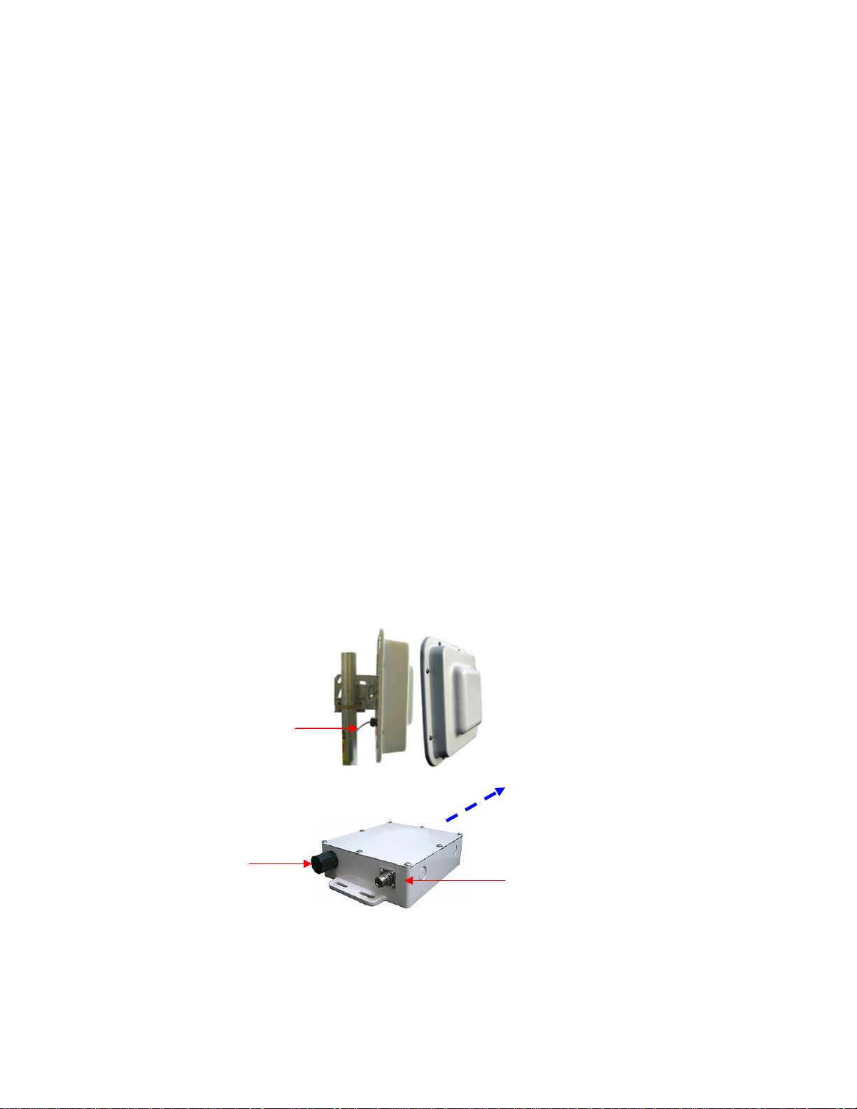
WAP-240 / WAP-500 Series
There have one RJ45 connector and one N-type RF connector as
weatherproof.
1” to 2” pole using included bracket kit, or wall mount using user supplied
screws
Cover Attachment
Cover Seal
High Performance EPDM Gasket
Solar Heat Rise
Overall Size (L x W x
H)
Weight
40oz (1.13kg)
RJ45 PoE and External
Metal pole for grounding
standard packaging.
The enclosure can be mounted to a wall using lag bolts or
masonry screws. It can also be attached to a pole using the
included pole clamps and U-bolts. When attaching to a pole
always makes sure the pole clamp is between the enclosure
and the pole as shown in the picture. This prevents stress
on the flange which could lead to cracking.
Note:
• Security screws, such as torx head screws, can be used
if it’s desired that the cover be removed only by qualifie d
personnel.
• Grounding is normally accomplished thru the po le
attach. If wall mounting, the installer should make sure
there is a ground wire running from one of the lag bolts
to an earth ground. Some paint may need to be scraped
from the flange area to affect a strong ground.
• Any feedthru connections like bulkhead connectors or
RJ45 feedthru should be gasketed so that they are
Specification for Enclosure
Mounting
Qty 8 8-32 x ¼” screw s
Internal Temperature ≤ 4 deg C above External Ambient
10” x 7.1” x 2.25” (254 x 180 x 57mm)
Antenna Connector toward
ground to avoid rain

16
RJ45 Ethernet Connector System (ECS)
Assembly
RJ45 connector from the socket.
Data
10BaseT, 100BaseT and 1000BaseT Networks
Class D per ISO/IEC 11801
Mechanical
Mating Cycles >500
Cat5 Cable Strain Relief
Sealing
IP68
Salt Spray
>1000h
Flammability
UL94VO
Thermal Shock
10 cycles -40 to +100 deg C
Temperature Range
-40 deg C to +85 deg C
Installation Hole Dia
0.787’ (20mm)
Overall Size (L x Dia)
3.75’ x 1.18’ (95 x 30mm)
Weight
2 oz (57gm)
• Remove the thin enclosure nut from the feedthru assembly. This can be
discarded. Loosen the compression nut completely.
• Insert the RJ45 connector thru the feedthru assembly
• Tighten the compr ession nut loosely
• Screw the entire feedthru assembly into the RJ45 housing w hich is
already mounted in the enclosure. There should be a rubber gasket
between the two assemblies. Tighten the feedthru assembly to create a
seal.
• The final step is to tighten the compres sio n nut until the gaskets are
tight around the Cat5 cable. Always push the cable toward the
connector while tightening to ensure good strain relief of cable to
connector.
Disassembly
• Loosen the compression nut t o relieve pressure on the Cat5 cable.
• Unscrew the feedthru asse mbly from the RJ45 housing
• Using a small screwdriver depress the RJ45 bayonet lock to release the
Specification for RJ45 ECS Connector
CAT5e per TIA/EIA 568B
Positive RJ45 bayonet coupling
17
RJ45 Field Installable Feedthru Connector
Assembly
Effective Cable Clamping
Range
0.2” to 0.5” (5mm to
12.7mm)
Enclosure Hole S i ze
8125” [13/16”], (20mm )
Certifications
CE
Waterproofing
IEC 529 Level 8 , IP68
Disassembly
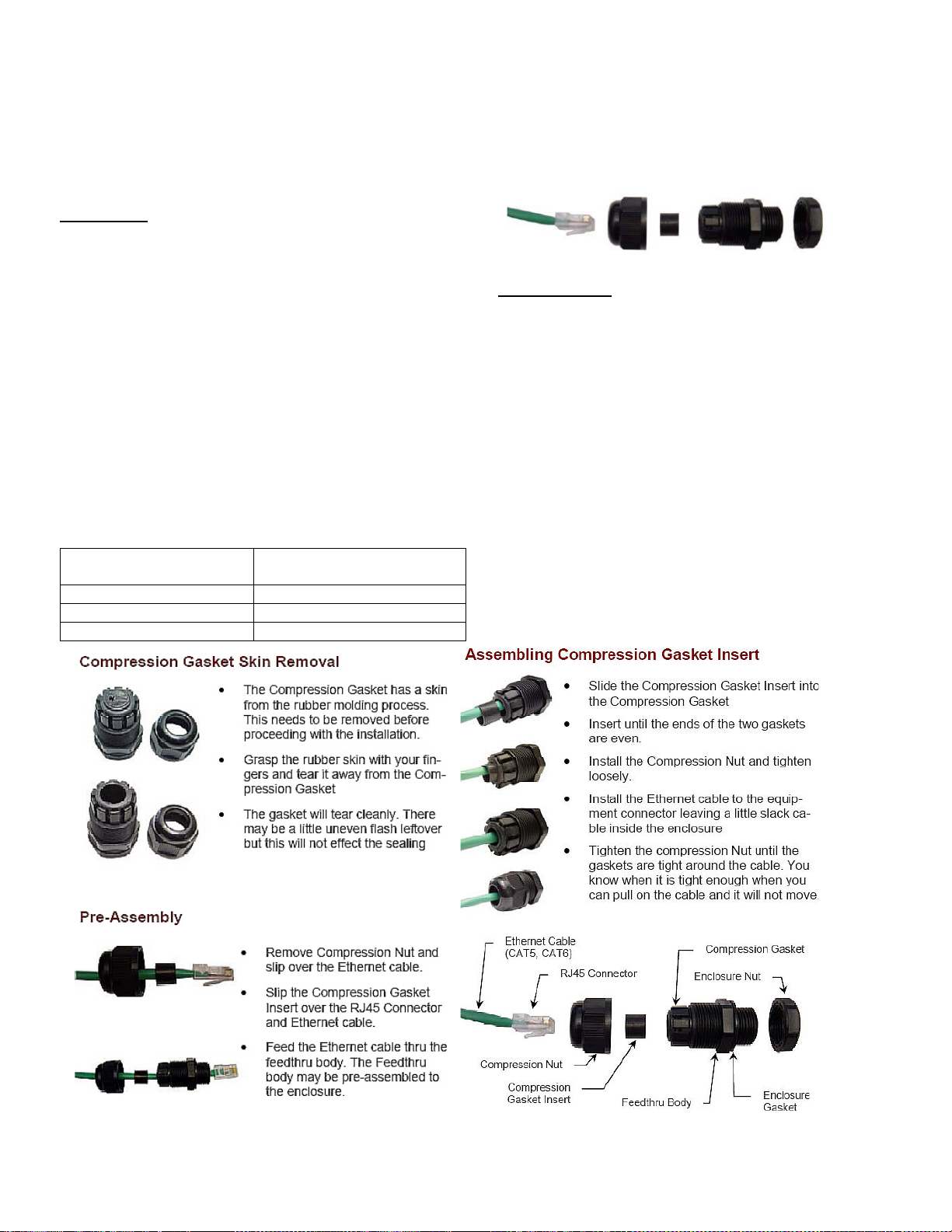
Please follow up following instruction if your CAP / WAP comes with such connector which is lack of RJ45 ECS
Installation
• The RJ45 Field Installable Feedthru system is used to
waterproof cable entries into outdoor enclosures to IP68
waterproofing standards. The material is UV stabilized for
long term outdoor applications.
• The unique design is “Field Installable” because it
accepts a fully pre-assembled Ethernet cable connector.
There is no need to terminate the cable during
installation. This gives the installer flexibility to use
standard pre-assembled Ethernet cables.
• The Feedthru can be pre-installed into an outdoor
enclosure such as a WAP-192 or a CAP-1920 Integrated
Antenna.
• The RJ45 Field Installable Feedthru allows for assembly
or disassembly of the Ethernet cable which gives the
installers the ability to change out the entire enclosure
Specification for RJ45 Field Connector
• Loosen and remove the Comp ression Nut
• Remove the Co mpression Gasket Assembly
from the Feedthru Body.
• Slide the RJ45 connector out of the enclosure
thru the Feedthru Body.
• If needed, the Ethernet cable can be removed
from the Compression Gasket Assembly but this
isn’t recommended because of possible damage
to the Compression Gasket Inser t.
• To Remove the Ethernet cable from the
Compression Gasket Assembly, first remove the
Compression Gasket Insert and then slide the
RJ45 Connec tor thru the Compression Gasket
Assembly, then slide the Compression Gasket
Insert and the Compression Nut over the RJ45
connector body.
• Inspect the Compression Gasket Insert for
damage before reuse.
18
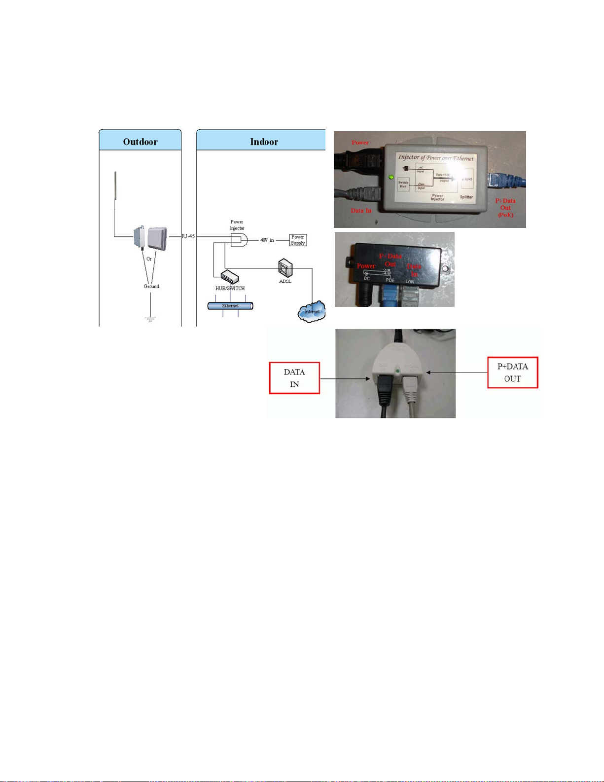
Power over Ethernet Unit
Plug the other end of the waterproof RJ-45 cable to the PoE device. The PoE device is
guaranteed only in indoor environment.
Caution: DON’T plug the power cord into PoE device before you finish install the
antenna and Ground wire to ensure the safety. If you are using WAP (Access Point)
then make sure that you connect to external antenna before power up device.
If the RJ-45 cable’s length is not long enough to connect to your network device for
indoor parts installation, you can extend the cable length. However, make sure the
maximum length of the RJ-45 cable is shorter than 100M (about 109 yards) for normal
operation under IEEE 802.3 standards.
When you plug the regular RJ-45 cable into the PoE device, you should use the regular
RJ-45 cable to plug into the ‘DATA IN’ of ‘Power Over Ethernet Kit’ to connect to
hub/switch or use the crosslink RJ-45 cable (Not included in the Packing List) to connect
with user’s PC. The waterproof RJ-45 cable must be connected to the ‘P+DATA OUT’
port.
Caution: Don’t plug the two cables inversely. It will damage the devices
We recommend you refer to the following illustration as a guideline for hardware
installation.

19
Lighten Protector / Surge Protector
WAP / CAP come with built in lighten or surge protectors:
WAP-240:
• Surge protection for 2.4GHz antenna systems
• Gas discharge tube design with multi-strike capability
• Allows DC voltage to pass, suitable for tower-top electronics
• Bi-directional protection
• Durable and waterproof aluminum body with ground lug terminal
WAP-500 / 520N Series:
• Handle multiple lightning strikes while requiring no maintenance
• Narrow band: 20% BW - 100MHz - 6GHz
• Wideband: .82 to 2.2GHz and 2.4 to 6GHz
• Ultra-low let-through
• Multiple strike 60kA transient capability
• RF Power capability to 3kW
CAP-2400 / CAP-5000 Series:
• Built in protector that is designed to protect Power-Over-Ethernet antenna
• Data Line Protection: 7.5V (pins 1,2,3,6)
• Power Line Protection: 60VDC (pins 4,5,7,8)
• Peak Pulse Current (10/1000us): 132 amp
• Response Time: < 5ns
• Maximum Shunt Capacitance: < 25pf
• Operating Temperature: -40C to +70C
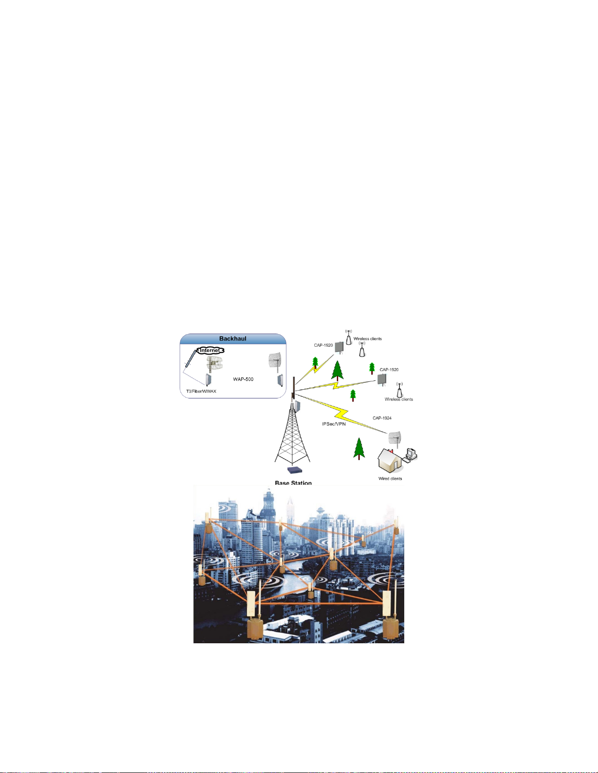
20
Introduction
WiBorne has developed deployments that maximizes up time reliability, while
minimizing the constraints on actual data throughput. The WiBorne solution focuses the
fail-safe functions at the most important element of the network, the backbone.
Maintaining a robust, hi-speed and redundant backbone is the most critical aspect of the
network. The result is that device provides system performance and reliability well
beyond that of competing technologies.
Overview
WiBorne's device wireless backbone radios are available in 900MHz, 2.4, 3.65, 4.9, and 5
GHz frequency bands. Each device micro cell base station includes an environmentally
controlled enclosure with thermostat controlled heater and fan, nine port router, and can
support up to six additional Ethernet devices (cameras, access points, etc.). Device is also
designed to support Pre-802.11n radio with software upgradeable to 802.11n, PreWiMAX radio (3.65GHz), and 802.11 a/b/g for WiFi hotspots. This highly flexible and
scalable system is built to grow with the needs of any network. Like all WiBorne
equipments, device is designed for easy installation and maintenance.
The device node box provides an innovative and easy method to create a self-healing hispeed backbone ring for reliable delivery of wireless broadband connectivity. The device

21
system is ideal for high-capacity metro backhaul, broadband access, systems bandwidth
injection, WiMAX systems, VOIP traffic and IP-based video surveillance.
The device is an outdoor NEMA rated box that houses a customized firmware. The router
provides OSPF functionality on the routed ports that connect to two WiBorne Point to
Point wireless backhaul radios which results in a layer 3 self-healing wireless networks.
The devices can also act as base radio or CPE for Point-to-Multiple-Points (P2MP). The
other three internal Ethernet (PoE) ports can be used in conjunction with any WiBorne
Access Point to provide wireless connections in a P2MP format. Each one of these
Ethernet (PoE) ports connects to an individual port on the router. This results in a unique
broadcast domain for each Access Point yielding higher performance at each cell. The
router board also connects to one or multiple MiniPCI radios wireless board that
functions as a WiFi Access Point. This device uses either an integrated panel antenna or
external sector / omni antenna to provide a hotspot solution. The other internal Ethernet
ports on the router can be used with any Ethernet or IP devices and can be configured as
bridge ports or router ports, for meeting different application requirements. It even can
connect with a daughter for additional radio modules. The device box is powered by 110240 V olts AC, 24 or 48 VDC, and is design to operate in temperatures between -40º C to
60º C.

22
User Name
admin
Password
Getting Started
It is always a good idea to first provision and test the equipment on the bench before
deploying them in the field. This is a particularly useful exercise for the novice user.
Management
The device can be configured using a Command Line Interface (CLI) from
HyperTerminal or console windows, Web Browser (HTTP) interface, or Winbox (GUI)
interface. Although all methods are comprehensive and powerful, the CLI method
provides more functionality
Password
The device unit is pre-configured with the following default account (admin) and
password. This user name and password will allow you to gain access through CLI, FTP,
HTTP, or W inbox.
Note: The password will default to a blank password if the unit is set to factory defaults.
The user name will still be admin.
Change admin' s pas s word
Just select the Password menu within the winbox GUI, for example:
Or, type the following command in the CLI:
[admin@WAP-520] > / password
old password:
new password: ******
retype new password: ******
This will change your current admin's password to what you have entered twice. Make
sure you remember the password! If you forget it, there is no recovery. You need to
reinstall firmware of the WAP-520!

23
Interfaces
We have three levels of interface, Web based, Windows based, and command line
interface through telnet or ssh remotely
• Web Based Interface: This is a web based configuration interface for wireless
firmware. Log in above to connect to this router - some of the most important
firmware features can be controlled within this interface. This is easy interface for
purpose of setting and routine maintain. We are improving W eb based GUI
gradually.
• Windows Based Interface: is the graphical configuration application for firmware.
Run it and connect to your WAP - all firmware functionality can be controlled with
this application.
• Command Line Interface (CLI): rem ot el y connect with telnet or ssh and you will
have access to the CLI of firmware, every function of firmware can be controlled with
it. This is particular useful for batch job to modify all sites remotely without much of
interface by human.
Web Based (Browser) Interface
The device features a convenient and easy-to-use web based configuration and
management tool. No additional software is needed on your computer other than a web
browser. The browser interface offers limited and basic functions, although the majority
can only be performed through command line interface (CLI).
To use the browser interface, the following must be present:
• An Ethernet (wired or wireless) connection between a PC and the device unit.
• Ethernet PC connection with IP/subnet that is routable to the device unit.
• A web browser on the PC (i.e. Microsoft Internet Explorer)
In order to use the browser interface – simply connect the device unit to a PC and type
the device’s IP address into the web browser (i.e. Microsoft Internet Explorer). This will
bring up the Login page.
Browser Interface Login Screen
The first page of the web browser is called the configuration page. The configuration
page offers the following options.
• Downloading Winbox
• Displaying Graphs
• Telnet into the device
• Documentation & License Information
Winbox can be downloaded from the router itself under the configuration page of the web

24
browser. The top left side of the configuration page offers a link to download the Winbox
application. The application can also be downloaded from website or associated CD.
Type the username (default: admin) and password (default wiborne [or blank if factory
reset]) and continue. This will bring up the router’s Interface page (Webbox)
You would see following menu for Quick Setup:
By clicking Advanced, it then goes to next menu.
Primary Features and Pages of the Browser Interface (Webbox)
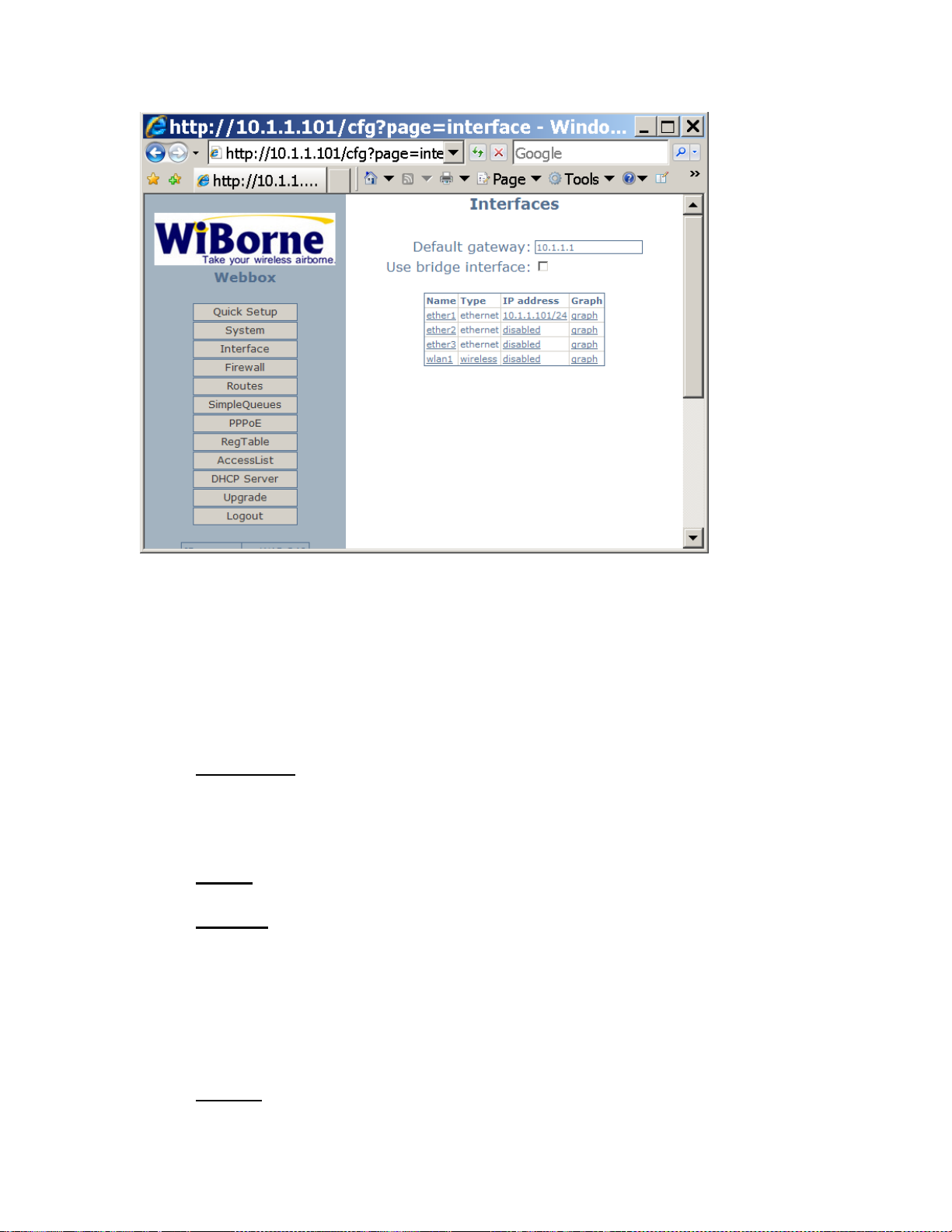
25
Navigation Column: Each page features a navigation column that runs along the lefthand side of the page. On the bottom of the navigation column is the current status of
the router including its System ID, IP address, Time, Date, CPU Utilization, Uptime, Disk
Space Free, Disk Space Total, Memory Free, Memory Total, Rx, Tx, AP, Clients, and
Timeout.
The navigation column also features buttons to each of the following pages:
• Quick Setup: This configures
o Wireless SSID/Band/WPA with either PPPoE client, DHCP client, or static
IP.
o Ethernet IP address, NAT, and parameters that acts as DHCP server.
• System: This page shows ID, Version, System Reset, Reboot, Change password,
and Web page refresh period.
• Interface: The interface name, type, IP address, enable/disable and graph are seen
on this page.
o Gateway IP, option for bridge interface
o Individual interference such as ether1, wlan1.
o For each ethernet, configure IP with static or DHCP
o For each wireless, configure: ssid/mode/band/authentication/forwarding,
security (WPA or none)
• Firewall: This page allows you to setup a basic firewall by selecting the Public
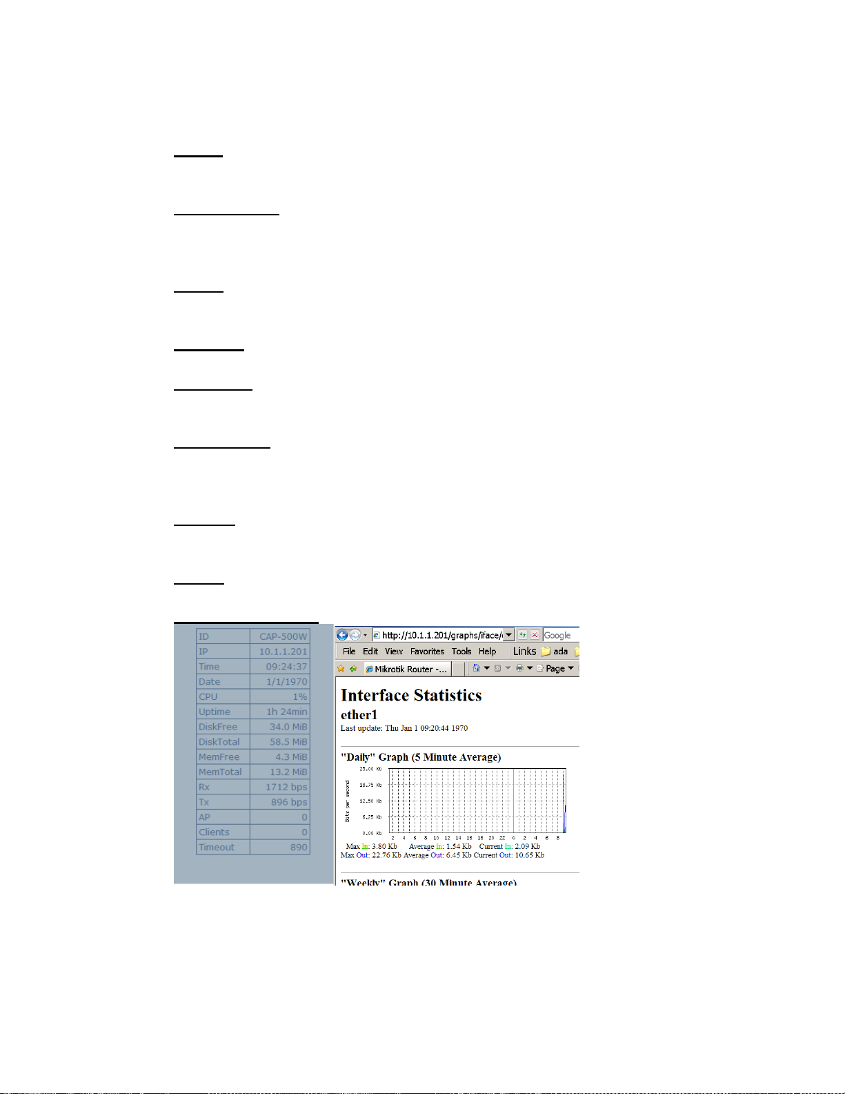
26
interface and check boxes of Protect customer, Protect router, and NAT.
• Routes: This page will display all routing information with capabilities of
adding static routes for each destination / netmask/gateway.
• Simple Queues: Simple Queues (QoS) page allows you to rate limit traffic on
the router. You can define Name, In/Out separated limitation, Target IP, Time and
Date for 7 x 24 or specific heavy traffic period during the day.
• PPPoE: Allows you to enable PPPoE on an interface and add users and
passwords.
• Reg Table: This page will show you current registered clients.
• Access List: This page will allow adding an Access List based on MAC
address, Interface, Authenticate and Forward settings.
• DHCP Server: This page will show you current DHCP server settings to
include current DHCP leases, with enable/disable, address range, Gate way IP,
DNS
• Upgrade: This page will allow you to upload an upgrade package or
downgrade.
• Logout: This link will end the current browser session with the router.
• Status and Graphics: showing
WebFig (Web Browser) Interface
WebFig is a web based WAP/CAP configuration utility available from OS V5.0. It is
accessible directly from the router and no additional software is required (except web
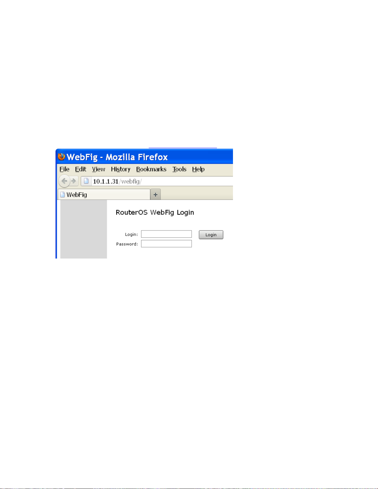
27
browser with JavaScript, of course).
As WebFig is platform independent, it can be used to configure router directly from
various mobile devices without need of software developed for specific platform.
WebFig is designed as an alternative of Winbox as shown on below. Both have similar
layouts and both have access to almost any feature of WAP/CAP.
Connecting to WAP/CAP
WebFig can be launched from the home page which is accessible by entering routers IP
address in the browser. For example, if you define IP address to be 10.1.1.31, then you
can access WebFig by entering http://10.1.1.31/webfig:
Default Login is ‘admin’ (without quote), and blank Password
Inter face Overvi ew
WebFig interface is designed to be very intuitive especially for WinBox users. It has very
similar layout: menu bar on the left side, undo/redo at the top and work are at the rest of
available space.
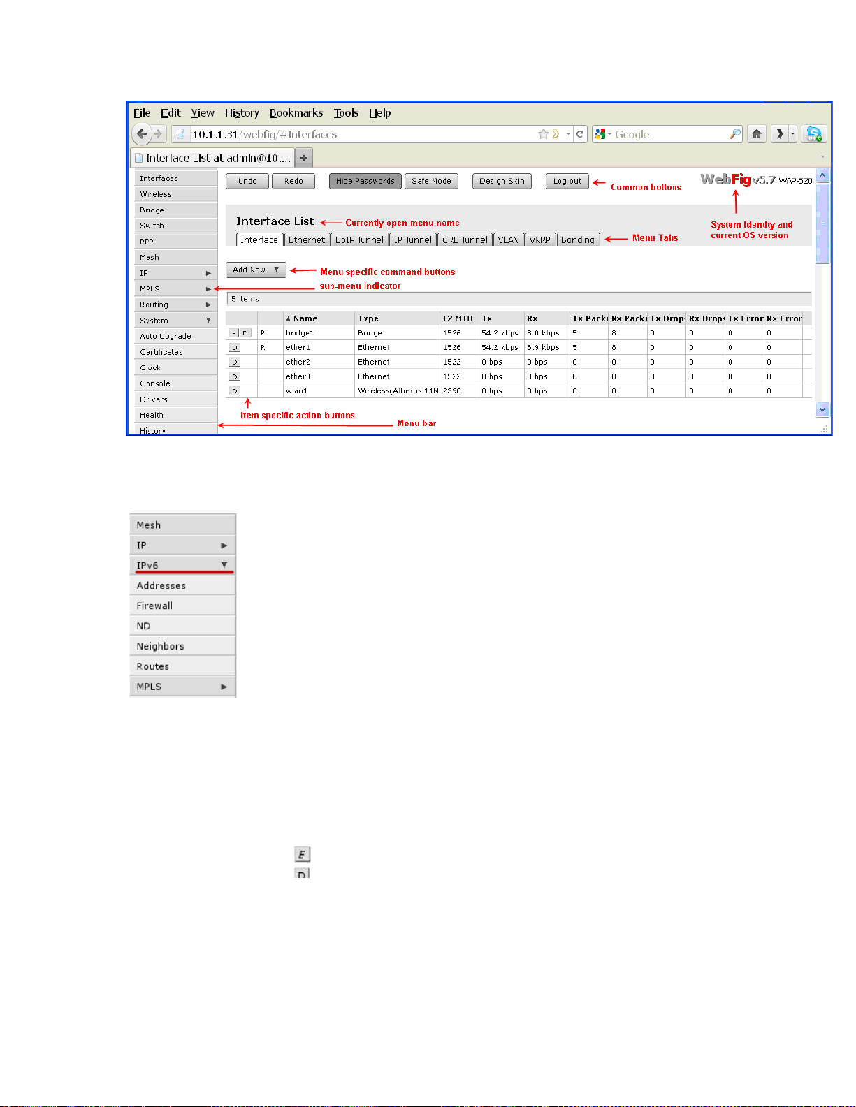
28
When clicking on such menu item, sub-menus will be listed and the arrow will be
Menu bar has almost the same design as WinBox menu bar. Little arrow on the right side
of the menu item indicates that this menu has several sub-menus.
pointing down, indicating that sub-menus are listed.
At the top you can see three common buttons Undo/Redo buttons similar to winbox
and one additional button Log Out. In the top right corner, you can see WebFig logo
and WAP/CAP model name.
Work area has tab design, where you can switch between several configuration tabs,
for example in screenshot there are listed all tabs available in Interface menu
(Interface, Ethernet, EoIP Tunnel, IP Tunnel,…).
Below the tabs are listed buttons for all menu specific commands, for example Add
New and Settings
The last part is table of all menu items. First column of an item has item specific
command buttons:
• - enable current item
Item configuration
When clicking on one of the listed items, webfig will open new page showing all
configurable parameters, item specific commands and status.
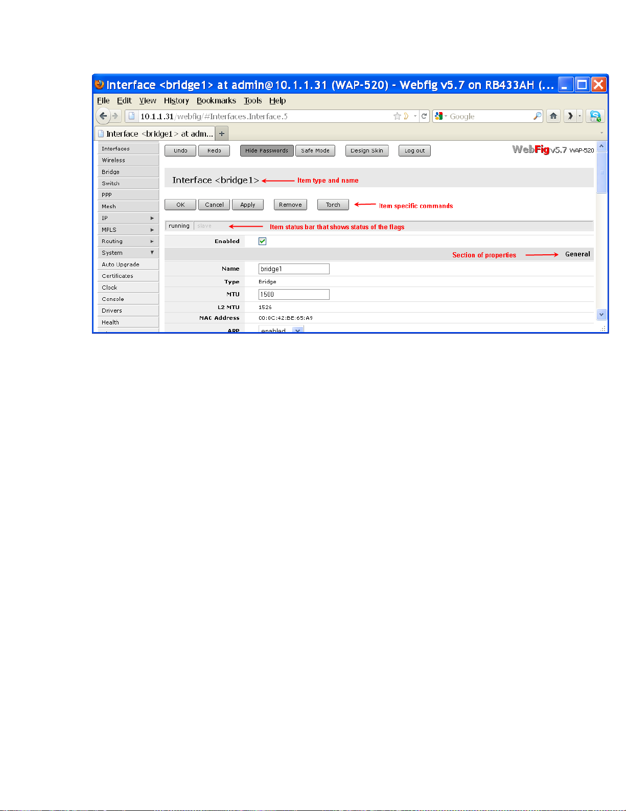
29
On the top you can see item type and item name. In example screenshot you can see that
item is an interface with name bridge1
There are also item specific command buttons (Ok, Cancel, Apply, Remove and Torch).
These can vary between different items. For example Torch is available only for
interfaces.
Common Item buttons:
• Ok - apply changes to parameters and exit;
• Cancel - exit and do not apply changes;
• Apply - apply changes and stay on current page;
• Remove - remove current item.
Status bar similar to winbox shows current status of item specific flags (e.g running flag).
Grey-ed out flag means that it is not active. In example screenshot you can see that
running is in solid black and slave is gre y-ed, which means that interface is running and
is not a slave interface.
List of properties is divided in several sections, for example "General", "STP", "Status",
"Traffic". In winbox these sections are located in separate tabs, but WebFig lists them all
in one page specifying section name. In screenshot you can see "General" section. Greyed out properties means that they are read-only and configuration is not possible.

30
Skins
Webfig skins is handy tool to make interface more user friendly. It is not a security tool.
If user has sufficient rights it is possible to access hidden features by other means.
Designing skins
If user has sufficient permissions (group has policy edit permissions) Design Skin button
becomes available. Pressing that toggle button will open interface editing options.
Possible operations are:
• Hide menu - this will hide all items from menu and its submenus;
• Hide submenu - only certain submenu will be hidden
• Hide tabs - if submenu details have several tabs, it is possible to hide them this
way;
• Rename menus, items - make some certain features more obvious or translate
them into your launguage;
• Add note to to item (in detail view) - to add comments on filed;
• Make item read-only (in detail view) - for user safety very sensitive fields can be
made read only
• Hide flags (in detail view) - while it is only possible to hide flag in detail view,
this flag will not be visible in list view and in detailed view;
• Add limits for field - (in detail view) where it is list of times that are comma or
newline separated list of allowed values:
o number interval '..' example: 1..10 will allow values from 1 to 10 for fiels
with numbers, example, MTU size.
o field prefix (Text fields, MAC address, set fields, combo-boxes). If it is
required to limit prefix length $ should be added to the end, for example,
limiting wireless interface to "station" only will contain
• Add Tab - will add grey ribbon with editable label that will separate the fields.
Ribbon will be added before field it is added to;
• Add Separator - will add low height horizontal separator before the field it is
added to.
Note:
• Number interval cannot be set to extend limitations set by OS for that field
• Set fields are argument that consist of set of check-boxes, for example, setting up
policies for user groups, RADIUS "Service"
• Limitations set for combo-boxes will values selectable from dropdown
 Loading...