

WIATEC MicroGuard-USB User Manual


MicroGuard-USB Instructions: GSM Remote for Parking Heaters
General
ALL RIGHTS RESERVED.
NO PART OF THIS MANUAL MAY BE REPRODUCED, TRANSCRIBED, STORED IN A
RETRIEVAL SYSTEM, TRANSLATED INTO ANY LANGUAGE OR COMPUTER LANGUAGE OR
TRANSMITTED IN ANY FORM OR BY ANY MEANS, ELECTRONIC, MECHANICAL,
PHOTOCOPYING, RECORDING OR OTHERWISE, WITHOUT THE PRIOR WRITTEN
PERMISSION OF THE COPYRIGHT OWNER.
THE COPYRIGHT OWNER GIVES NO WARRANTIES AND MAKES NO REPRESENTATIONS
ABOUT THE CONTENTS OF THIS MANUAL AND SPECIFICALLY DISCLAIMS ANY IMPLIED
WARRANTIES OR MERCHANTABILITY OR FITNESS FOR ANY PURPOSE.
THE COPYRIGHT OWNER RESERVES THE RIGHT TO REVISE THIS MANUAL AND TO MAKE
CHANGES FROM TIME TO TIME IN ITS CONTENTS WITHOUT NOTIFYING ANY PERSON OF
SUCH REVISIONS OR CHANGES.
Copyright: © WIATEC GMBH
Pictures: istockphoto.com, wiatec gmbh
14. January 2017
E-Mail: support@microguard.de
Seite 2 Notification & Control by mobile phone

MicroGuard-USB Instructions: GSM Remote for Parking Heaters
1. Introduction
The purpose of this manual is to provide general instructions for installation
of our MicroGuard-USB devices into cars equipped with parking heaters
and to explain parameter settings necessary for operation with different
heater manufacturers and models. Dedicated manuals for different heaters
are available in German language on our website:
http://microguard.de/downloads/anleitungen-microguard-usb
Please use those manuals for the individual connection of our device to a
particular heater model.
2. Scope of delivery
In the delivery you will find the following content:
• MicroGuard-USB (control device),
- special version with power conversion module +12V or
- a special version with modification for your specific connection
• Connectors with 15cm cable (will need individual extension)
• Option: external temperature sensor(s), if ordered
• Option: y-cable for several temperature sensors (if ordered)
For GSM remotes we offer only external temperature sensors.
3. General switching function
MicroGuard-USB is equipped with two output and two input lines which can
be used for heater switching and switch control (or alarm lines).
• Older heaters can be controlled using +12V signals (orange
output) or ground output (brown).
• Newer heaters use Bus signals (W-Bus, LIN, CAN). We offer a
special modul equipped with W-BUS signals. In other cases we
adopt the connection of our module to an existing control device
(like timer or wireless receiver).
http://www.microguard.de V1.0 Seite 3

Anleitung: MicroGuard – Der kleine Mobilfunkwächter
With MicroGuard-USB a temperature sensor can be used to feedback on
temperature inside the car.
4. External temperature sensor - characteristics
Device: Dallas Semiconductor DS18B22:
• temperature range: -55°C bis +125°C
• Accuracy: +/- 0.5°C for -10°C < T < +85°C, +/- 2°C otherwise
• External sensors are water proof in a metal eclosure:
http://microguard.de/file_download/54/AnleitungTemperaturwaec
hter.pdf
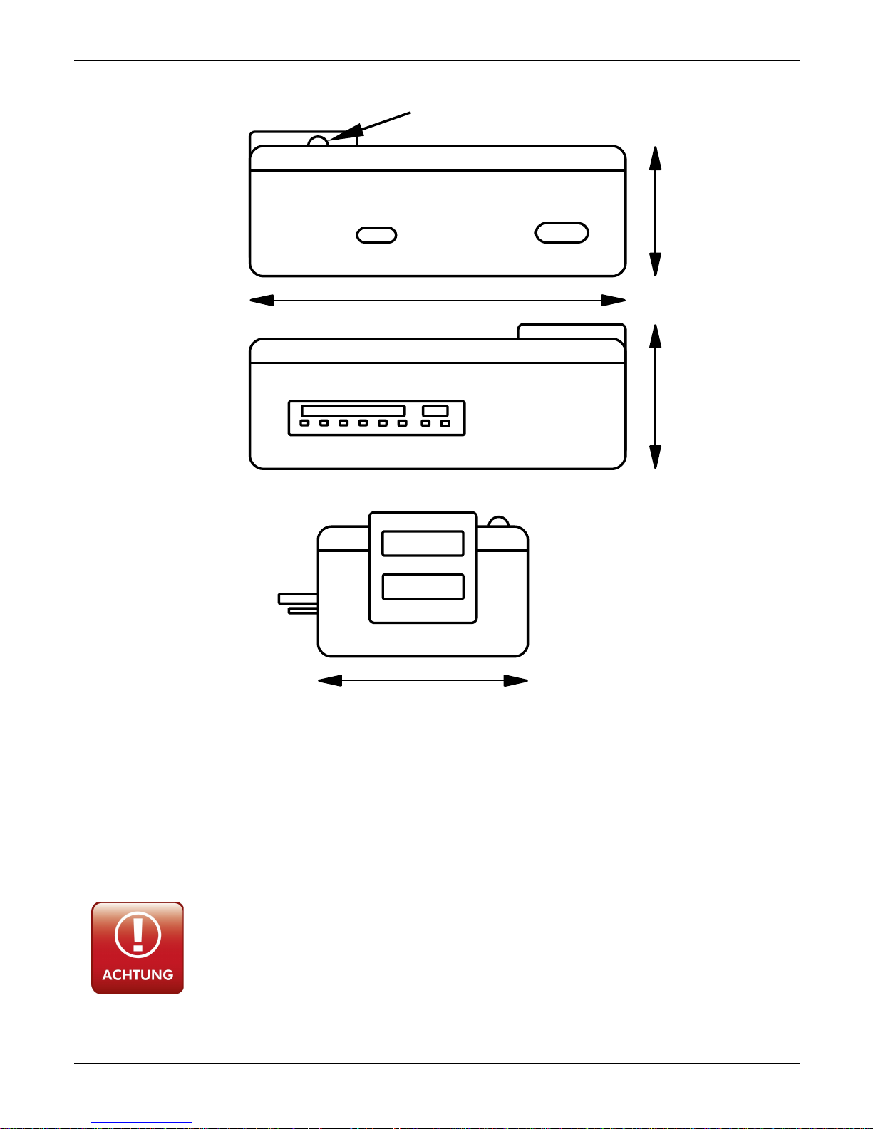
5. Aufbau und Schnittstellen
Fig. 1 is showing MicroGuard-USB:
• Micro-USB: power supply connector, used only for some types of
GSM control configurations, mainly with remote senders
• Mini-USB: port for external T-sensors
• Ein-/Ausgänge: input and output lines, +12V power supply
• USB-Port: connection to Surfsticks (PORT1)
• LED: function indicator
Seite 4 Überwachung | Benachrichtigung | Steuerung per Handy
MicroGuard-USB Instructions: GSM Remote for Parking Heaters
6. Connection to heaters controlled by +12V or ground
Use always a 5A fuse for power supply connections.
Never connect directly to car battery.
Wrong power connection will destroy the device!
http://www.microguard.de V1.0 Seite 5
Fig. 1: MicroGuard-USB Module
Ein-/Ausgänge
USB-Port
Signal-LED
Micro-USB
Mini-USB
Signal-LED
35mm
60mm
22mm24mm
PORT1
PORT2
Anleitung: MicroGuard – Der kleine Mobilfunkwächter
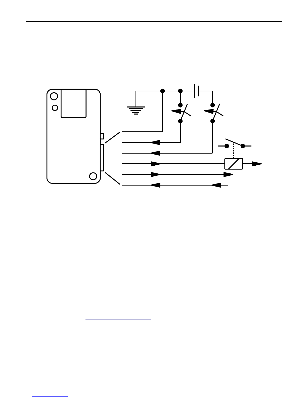
Fig. 2 shows a general scheme for potential connection of MicroGuard-USB
to external devices. You can use the orange line to control heaters by +12V
signals. You can use brown line to control heaters using ground signals or
convert ground to voltage-independent switch driving a relay.
Fig. 3 Shows usually used outputs and power supply lines used for GSM
controls for heaters. +12V battery voltage is vonnected to red line, ground
to black. Switched signal on orange (+12V) and brown (ground) are
available.
For individual connection schemes to divers heater models, please refer to
the schematics described in the dedicated German installation instruction.
If there are questions about the connection schemes, please contact our
support per mail: support@wiatec.de
Seite 6 Überwachung | Benachrichtigung | Steuerung per Handy
Figure 2: General connection scheme for MicroGuard-USB
Ein-/Ausgänge
rot
orange
braun
grün
gelb
schwarz
Masse
Alarm Alarm
+12V
geschaltete Masse
+12V
geschaltete +12V
geschaltete Masse
 Loading...