

Wiard GR-371 User Manual
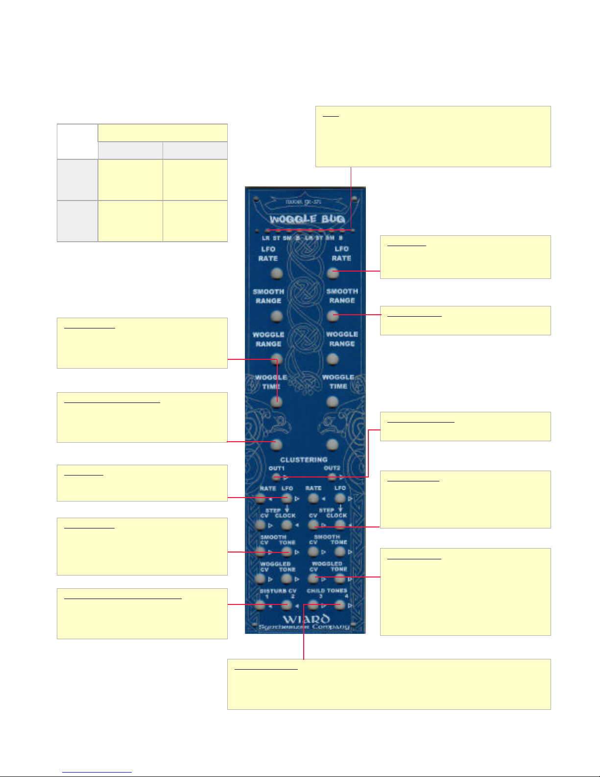
Wiard Model GR-371 Woggle Bug
out tone and CV.
SMOOTH TONE out (1-6 octaves).
off when the woggle PLL is in lock.
Woggle Bugs. Audio is output when B LED is lit.
LFO [out] 0-10v square wave from 0.05-50 Hz.
[out].
SMOOTH RANGE knob.
Woggle Bug and 2 goes to right.
TONE [outs] of each Woggle Bug. Sound affected by all 10 knobs.
Wiard GR-371 Woggle Bug
Rev: 031001
LEDs
LR (LFO Rate) Green, lit when LFO [out] is at 10v.
Woggle
Bug
Audio
Two circuits - WOG1, WOG2
Generator Processor
Out1, Out2
Smooth Tone
Woggle Tone
Child Tones
None
ST (Stepped Voltage) Red/orange, indicates voltage at STEPPED CV
[out].
SM (Smooth Voltage) Red/orange, indicates voltage at SMOOTH CV [out]
B (Bug Light) Yellow, indicates audio pulse rates at OUT1 [out] and OUT2
[out]
Control
Voltage
Woggle Control
WOGGLE RANGE [knob] Sets the range of
WOOGLED TONE [out] (1-6 octaves).
WOGGLE TIME [knob] Sets the lock in time of the
woggle oscillator phase locked loop. The B lamp is
Step and Tone Range Setting
CLUSTERING [knob] Sets the range of probable
values for the STEP CV [out]. At minimum, equal
probability of voltage from 0 – 10 V at STEP CV
[out]. At maximum, limits change to next value samples tend to cluster.
LFO Section
RATE [in] 0-10v added to LFO RATE to vary LFO
rate from 0.05-50 Hz.
Smooth Output
SMOOTH CV [out] 0-8v smooth random voltage.
Probable rate of change set by LFO RATE knob
added with RATE [in].
SMOOTH TONE [out] 0-10v audio rate square
wave, the frequency range of which is set by the
Woggle PLL/VCO Disturb CV Inputs
DISTURB CV 1, DISTURB CV 2 [in] 0-10v control
voltage added to STEP CV out at the WOGGLE TONE
in. WOGGLE RANGE knob must be set to less than
maximum for this input to work, 1 goes to left
Step CV
Smooth CV
Woggled CV
LFO (SQR)
None
LFO Control
LFO RATE [knob] Value added to voltage at RATE
[in], controls LFO rate linearly (1 cycle / 20 sec to
50 cycles / sec). Sets rate of change of SMOOTH
Oscillator Range
SMOOTH RANGE [knob] Sets the range of
Main Output Section
OUT1, OUT2 [out] Primary audio outs for the
Stepped Output
STEP CV [out] 0 – 10V stepped random voltage. A
new voltage is selected at each positive going clock
pulse at STEP CLOCK [in].
STEP CLOCK [in] New voltage selected each time a
positive clock pulse crosses 1.5V. Normalized to LFO
Woggled Output
WOGGLED CV [out] 0 – 8V product of the smooth
and stepped random voltages. The demodulated
output of a phase locked loop frequency modulation
detector tracking the smooth tone and being
disturbed by the step control voltage. PLL loop lockin time is set by WOGGLE TIME knob. When the PLL
is in lock, the B LED is off.
WOGGLED TONE [out] 0 – 10V audio rate square
wave, the frequency range of which is set by the
WOGGLE RANGE knob.
© 1996-2003 Wiard Synthesizer Company – design by Bill Sequeira/Axon Hillock Source of Uncertainty
Child Tone Outputs
Child tones are the XOR (ring mod) product of the two Woggle Bug parents.
CHILD TONES 3 [out] – 0 – 10V pulse wave which is the audio XOR product of the SMOOTH TONE
[out] of each Woggle Bug. Sound changed by both SMOOTH TONE controls.
CHILD TONES 4 [out] – 0 – 10V pulse wave which is the audio rate XOR product of the WOGGLE
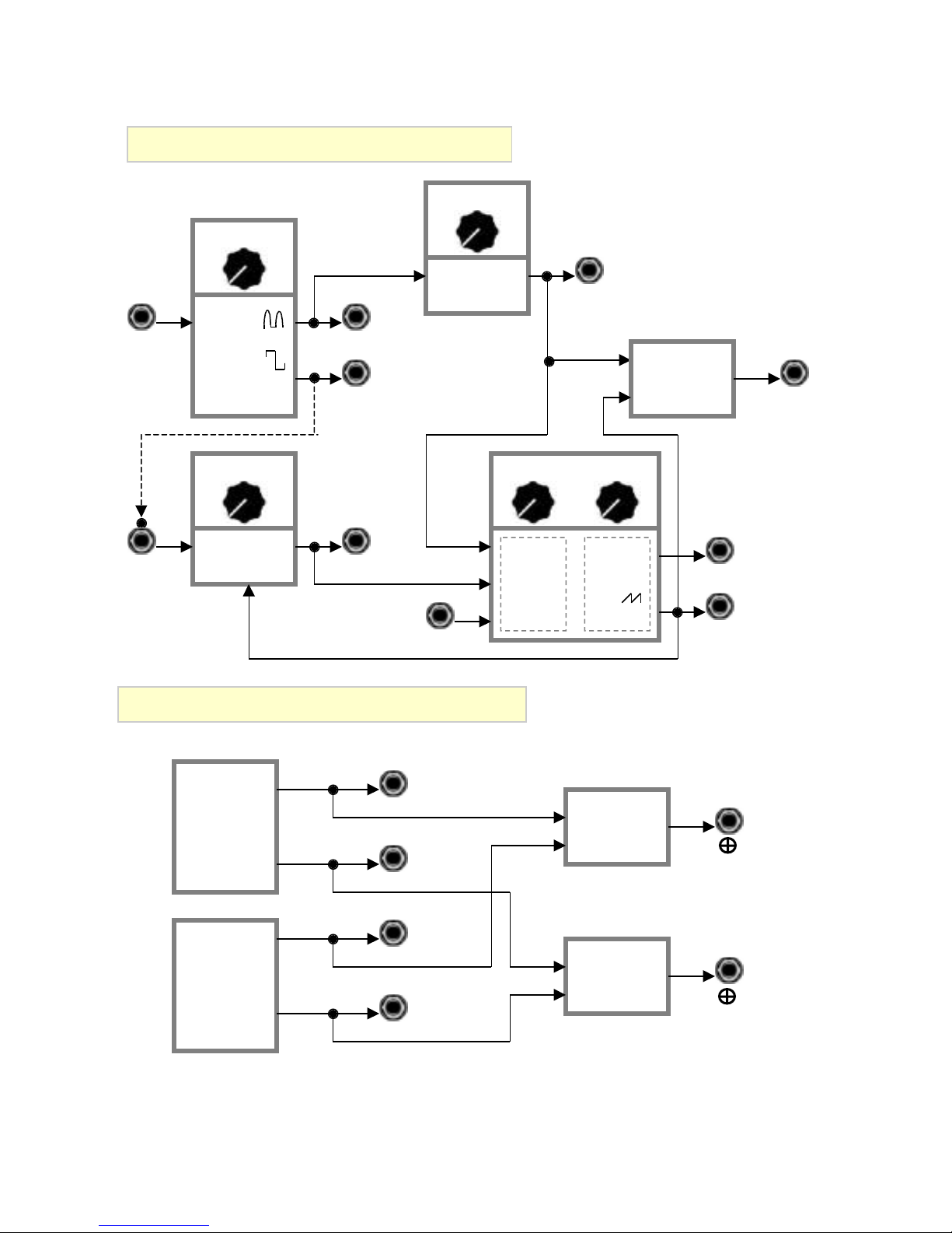
Wiard Model GR-371 Woggle Bug
Woggle Bug First Order Units
SMOOTH
RANGE
RATE
LFO
Square
LFO RATE
Smooth
Random
Square
LFO
CLUSTERING
S&HCLOCK
Woggle
Saw
SMOOTH CV
LFO
STEP CV
DISTURB CV 1
VCO
Freq
Cv
WOGGLE
TIME
PLL
SMOOTH TONE
WOGGLE
RANGE
Saw
VCO
RING
MOD
(XOR GATE)
OUT1
WOGGLED CV
WOGGLED TONE
Woggle Bug Second Order Units
SMOOTH TONE
WOGGLED TONE
WOG1
SMOOTH TONE
WOGGLED TONE
WOG2
RING
MOD
(XOR GATE)
RING
MOD
(XOR GATE)
CHILD TONES
OUT3
Smooth Smooth
OUT4
Woggle Woggle
© 1996-2003 Wiard Synthesizer Company – design by Bill Sequeira/Axon Hillock Source of Uncertainty
 Loading...