

Page 1
Wiard Model GR-331 Envelator
remains on. When no LEDs are lit, the voltage is below 2 volts.
envelope completed the attack cycle time
Each envelope is individually switched.
the envelope function.
Wiard GR-331 Dual Envelator
Rev: 031001
Dual
Envelator
Audio
Control
Voltage
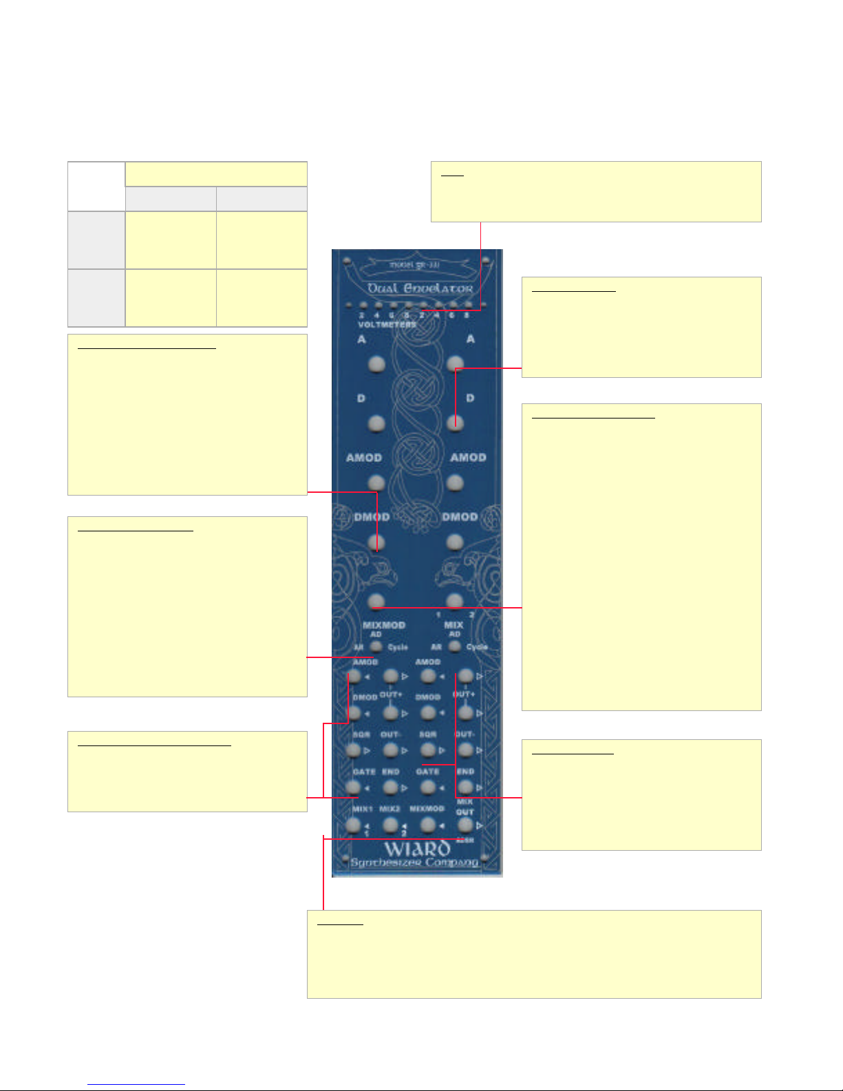
Envelope Modulation Controls
AMOD [knob] - Attack Modulation Setting - Attack
Modulation allows for voltage control of the attack
time. This control allows adjustment of the amount
of modulation to the attack time as input into the
AMOD input jack. Positive voltages decrease
segment time.
DMOD [knob]- Decay Modulation Setting - Decay
Modulation allows for the voltage control of the
decay (or release) time. This control allows
adjustment of the amount of modulation to the
decay/release time as input into the DMOD input
jack. Positive voltages decrease segment time.
Envelope Mode Selection
AR/AD/Cycle [switch] - This switch determines
the function of the envelopes. When set to AR, the
envelope will act as an AR envelope, maintaining
full level until GATE [in] goes “low”. In AD mode,
the envelope acts as an AD envelope, and will begin
decay as soon as the attack stage is complete. The
END output “pulses” when the decay stage is
complete, in Cycle mode, this pulse is fed back to
the envelope input, and will force the envelope to
re-trigger (oscillate). In this mode, the Envelator
output functions as a shaped triangle waveform
LFO. When in Cycle mode, the SQR output acts as
a square wave LFO with the pulse width determined
by the settings of the A and D controls. This output
can also be used to clock the Wiard Sequantizer.
Two circuits - ENV1, ENV2
Generator Processor
Cycle mode runs
into audio
range
Envelopes DC-coupled
Short evenlopes
triggered at
audio rate (into
GATE [in])
fader will mix
control voltages
cross-
LEDs
The LED bank is split into two sections, where each 4-lamp section shows
the current output value (in volts) of its respective envelope. The LEDs
increment in 2 volt steps. When the voltage is above 8 volts, the last LED
Envelope Controls
A [knob] Attack - The attack time for the envelope.
D [knob] Decay/Release - The decay and/or release
time for the envelope. If the AR/AD/Cycle switch is
set to AR, this control is the release time used when
a gate signal is removed from the GATE input jack.
If the switch is set to AD or Cycle, this control is the
decay time measured from the time that the
Mixer/Cross-fade Controls
MIXMOD [knob] - The Mixture Modulation control is
an attenuator for the MIXMOD voltage input. This
provides for the voltage control of mixed envelope
(or other signal) cross-fading. When used as a
voltage controlled ADSR, this acts as the sustain
voltage control.
MIX [knob] - The Mix control will cross-fade from
the MIX1 and MIX2 input jacks, sending the output
to the MIXOUT output jack. When the Mix control is
used for the two envelopes in the Envelator, this
control will allow you to create an ADSR:
• Use Envelope 1 in AD mode, Envelope 2 in AR
mode.
• The positive outputs of the two envelopes are
normalized to the MIX1 and MIX2 inputs (as
indicated by the 1 and 2 below the in arrows).
• Set the MIX control to the 12 noon position
(evenly mixing the two envelopes).
• Both attack stages will affect the attack stage,
then the decay stage of Envelope 1 will drop
the voltage to the sustaining level (as
controlled by the MIX control). When the
gate is released, the release stage of
Envelope 2 will provide a release stage for the
overall envelope shape.
• The MIXMOD knob behaves like a normal
“sustain” level control, providing voltage
control of the sustain level.
Envelope Trigger and Modulation
AMOD [in] - Voltage control input for Attack rate
modulation.
DMOD [in] - Voltage control input for
Decay/Release rate modulation.
GATE [in] - The gate or trigger input used to start
© 1996-2003 Wiard Synthesizer Company – design by Bill Sequeira/Axon Hillock Voltage Controlled Envelope Generator
Envelope Outputs
END [out] - When the Decay (or Release) phase of
the envelope is complete, a “pulse” is output from
this jack.
OUT+ [out] - The positive envelope output.
OUT- [out] - The negative envelope output.
SQR [out] - The output of the trigger latch, where
the signal goes high during the attack phase and
goes low for the decay portion of the envelope.
Mixer I/O
MIX1 [in] - Input 1 for the Mix function. This input is normalized to the OUT+ output of Envelator 1.
MIX2 [in] - Input 2 for the Mix function. This input is normalized to the OUT+ output of Envelator 2.
MIXMOD [in] - An input signal that is added to the MIX control to cross-fade from MIX1 to MIX2
input.
MIXOUT/ADSR [out] - The output of the Mix function. This output is normally a mix of the two
Envelator positive outputs (ADSR).
Page 2
Wiard Model GR-331 Envelator
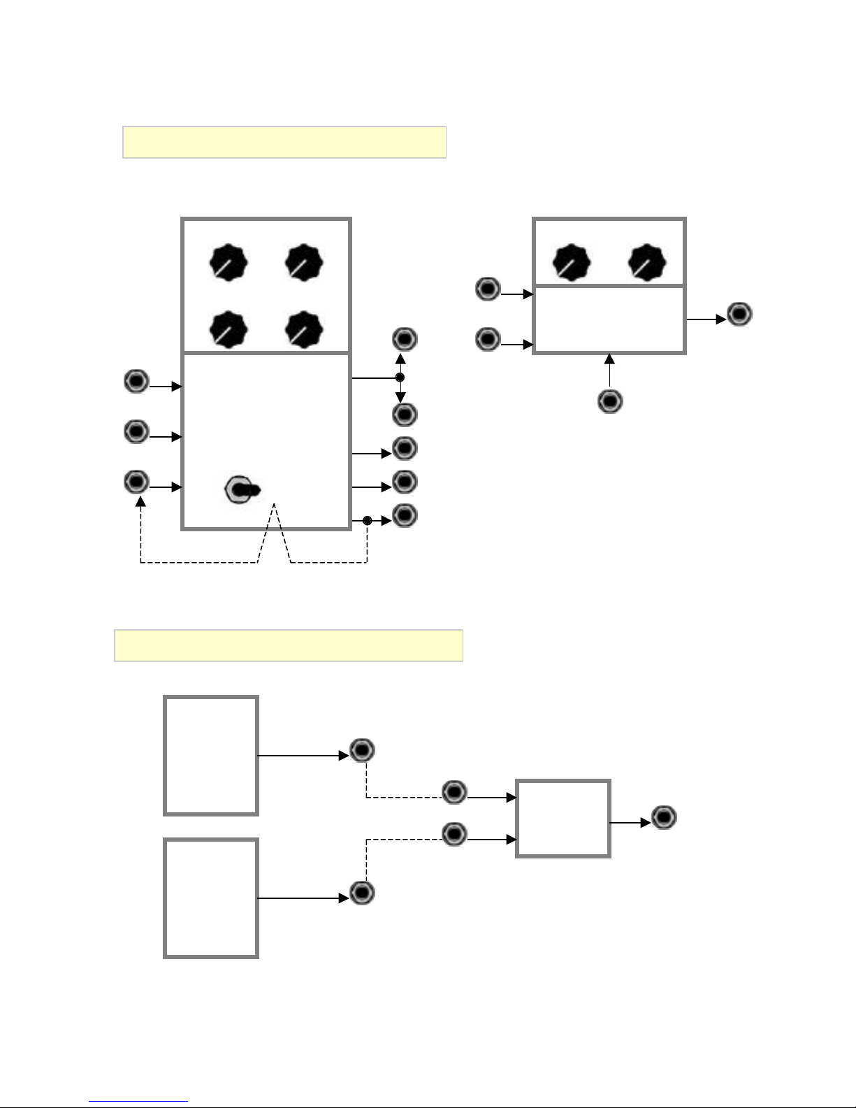
Dual Envelator First Order Units
A
AMOD
AMOD
DMOD
GATE Cycle
Cycle
ENVELATOR
AD
AR
D
DMOD
OUT+
OUT+
OUT-
SQR
END
MIX1
MIX2
MIX MIXMOD
MIX OUT
CROSSFADE
MIX
MIXMOD
Dual Envelator Second Order Units
OUT+
MIX1
ENV1
MIX2
MIX
OUT+
MIX OUT
ADSR
ENV2
© 1996-2003 Wiard Synthesizer Company – design by Bill Sequeira/Axon Hillock Voltage Controlled Envelope Generator
Page 3

Wiard Model GR-331 Envelator
Dual Envelator Module Description
The Wiard envelope generator, the Envelator , is a multifunction dual slope linear function generator. The module
contains two identical units.
The attack and decay slopes are individually voltage
controllable with input attenuators. Each unit outputs the
envelope, inverse of the envelope (negative going envelope),
a voltage step signal during the attack phase, and a pulse at
the end of the decay phase. The gate input has a three
position switch which selects: Attack-Release where the
output remains high as long as the gate is high, Attack-
Decay where the decay phase begins immediately after the
attack phase regardless of the gate level at the gate input.
Cycle where the gate input is connected to the end pulse
which causes the unit to act as an low frequency oscillator
(LFO). The LFO extends into the low audio range and has
triangle and square outputs. Any triangular or sawtooth shape
or pulse width can be adjusted by the attack and decay
controls.
The module also contains a DC coupled voltage controlled
cross-fader which forms the sustain control when patched as
a classic ADSR. It can also be used to mix two modulation
sources when patched as two LFOs. The cross-fader will also
handle audio signal through the full audio range. This is useful
for replicating oscillator waveshapers which cross-fade from a
sine wave signal to a waveform with higher harmonic content.
An example would be the Buchla Model 258 oscillator.
The Envelator module contains:
• Two Multi-mode envelope generators/oscillators which
will work in the low audio range
• A voltage "cross-fader" which will work both for control
voltages and audio signals
© 1996-2003 Wiard Synthesizer Company – design by Bill Sequeira/Axon Hillock Voltage Controlled Envelope Generator
Page 4

Wiard Model GR-331 Envelator
Dual Envelator Example Patches
Assumptions
o Notation used: MPN (see Modular Patch Notation (MPN)
Explained for a discussion on MPN)
o Only one module: Envelators.
o Two envelator circuits in a Dual Envelators module: Env1,
Env2.
Hello World
Top Envelators
Env1.Controls
[(AMOD, DMOD)=7,
A=5, --Attack
D=11, -- Release
AR/AD/CYCLE SWITCH=AR]
Env2.Controls
[(AMOD, DMOD)=7,
A=5, --Attack
D=11, --Decay
AR/AD/CYCLE SWITCH=AD]
Controls
[MIXMOD=7,
MIX=12] --Sustain
Connect
[+VC ATTACK -> (Env1.AMOD, Env2.AMOD),
+VC DECAY -> Env2.DMOD,
+VC RELEASE -> Env1.DMOD,
+VC SUSTAIN -> MIXMOD,
KBD.GATE -> (Env1.GATE, Env2.GATE),
MIX OUT -> +VCF and +VCA]
Comment
The classic ADSR attack patch. Both A knobs control
the attack. Vary all AMOD and DMOD, and MIXMOD
controls for different results.
Single Voice Tone
in effect MIXMOD is acting as a VCA, and the patch as
a whole produces a voice. Not keyboard tracking.
Elementary Chaotic System
Top Envelators
Env1.Controls and
Env2.Controls
[(AMOD, DMOD)=5,
(A, D)=5,
AR/AD/CYCLE SWITCH=Cycle]
Controls
[MIXMOD=7,
MIX=12]
Connect
[Env1.OUT+ -> (Env2.AMOD, Env2.AMOD),
Env2.OUT+ -> (Env1.AMOD, Env1.AMOD),,
MIX OUT -> +VCF OR +VCA]
Comment
Vary all A and D controls for different results.
Alternating LFOs
Top Envelators
Env1.Controls
[(AMOD, DMOD)=7,
(A, D)=3,
AR/AD/CYCLE SWITCH=Cycle]
Env2.Controls
[(AMOD, DMOD)=7,
(A, D)=12,
AR/AD/CYCLE SWITCH=Cycle]
Controls
[MIXMOD=7,
MIX=12]
Connect
[Env2.OUT+ -> Env1.OUT+,
MIX OUT -> +LFO SIGNAL]
Top Envelators
Env1.Controls
Comment
The output of the LFOs will alternate.
[A=5,
D=12,
Audio or LFO Synch
AR/AD/CYCLE SWITCH=AR]
Env2.Controls
[(AMOD, DMOD)=5,
(A, D)=12,
AR/AD/CYCLE SWITCH=CYCLE]
Controls
[MIXMOD=5,
MIX=7]
Connect
[+DUMMY PLUG -> MIX1,
Env1.SQR -> MIX2, --Optional
Env1.OUT+ -> MIXMOD,
Top Envelators
Env1.Controls and
Env2.Controls
[(A, D)=3,
AR/AD/CYCLE SWITCH=Cycle]
Controls
[MIXMOD=5, --Full on
MIX=7]
Connect
[Env1.SQR -> Env2.SQR,
MIX OUT -> +MON]
KBD.CV -> (Env2.AMOD, Env2.DMOD),
KBD.GATE -> Env1.GATE,
Balanced Modulation
MIX OUT -> +VCF OR +VCA]
Top Envelators
Comment
In this patch, Env2 acts as an oscillator that is
controlled by a keyboard pitch, while Env1 is used to
control a VCA (using the mixer as a VCA) triggered by
a keyboard gate signal. MIXMOD cross-fades from no
signal (dummy plug) to the tone produced by Env2, so
© 1996-2003 Wiard Synthesizer Company – design by Bill Sequeira/Axon Hillock Voltage Controlled Envelope Generator
Env1.Controls and
Env2.Controls
[(A, D)=3,
AR/AD/CYCLE SWITCH=Cycle]
Connect
[Env2.OUT+ -> MIXMOD,
Page 5

Wiard Model GR-331 Envelator
Comment
Also called Ring Modulation, cross-fades between
phase inverted signals. Note that Env1.OUT+ is
normalized to MIX1.
Trigger Delay
Top Envelators
Env1.Controls
Connect
Comment
Env1 is used to create a delay before Env2 is triggered.
Hence Env1.END triggers Env2.
Pulse Bursts
Top Envelators
Env1.Controls
Env2.Controls
Controls
Connect
Env1.OUT- -> MIX2,
MIX OUT -> +MON] --Balanced mod out
[A=5,
D=11]
[KBD.GATE -> Env1.GATE,
Env1.END -> Env2.GATE,
Env1.OUT- -> MIX2,
Env2.OUT+ -> +VCF OR +VCA] --Delayed env
[(AMOD, DMOD)=7,
A=9,
D=5,
AR/AD/CYCLE SWITCH=AD]
[(AMOD, DMOD)=7,
(A, D)=12,
AR/AD/CYCLE SWITCH=CYCLE]
[MIXMOD=5,
MIX=7]
[+DUMMY PLUG -> MIX1,
Env1.SQR -> MIXMOD,
Env2.SQR -> MIX2,
KBD.GATE -> Env1.GATE,
MIX OUT -> +Envelope trigger input] – Pulse
Burst
JOYSTICK.X -> MIX1, --+10v signal
Env1.SQR -> MIXMOD,
MIX OUT -> Env2.GATE, --Inverter
KBD.GATE -> Env1.GATE]
Comment
Env2 starts at the end of Env1’s attack phase. In
effect, MIX OUT acts as a logic inverter.
Comment
Used to create roll (>2) or flam (=2) triggers. Env1
creates a square long envelope while Env2 generates
short square pulse train, which causes a burst of short
pulses (Env2) for the duration of Env1. So Env1 is
used to trigger the bursts. Vary Env1.A for different
numbers of pulses, and Env2.A for pulse width and
Env2.D for pulse spacing.
Quadrature Envelope
Top Envelators
Env1.Controls and
Env2.Controls
[(A, D)=12,
(AMOD, DMOD)=7,
AR/AD/CYCLE SWITCH=any value]
Controls
[MIXMOD=5,
MIX=7]
Connect
[+DUMMY PLUG -> MIX2,
© 1996-2003 Wiard Synthesizer Company – design by Bill Sequeira/Axon Hillock Voltage Controlled Envelope Generator
 Loading...