

Mudguard Assembly Instructions
www.whyte.bike


CAUTION
Whilst fitting these mudguards:
• Confirm they are large enough for the tyres fitted to your bicy-
cle. “38mm” mudguards are suitable for Whyte Cambridge,
Cambridge Varsity, Carnaby, Charing Cross, Cornwall, Devon,
Dorset, Kings Cross, Pimlico, Portobello, Shoreditch, Somerset,
Stirling, Suffolk, Sussex, Victoria & Whitechapel models (Rigid
forks). “46mm” mudguards are suitable for Whyte Caledonian,
Chiltern, Coniston, Malvern & Ridgeway models (Suspension
Forks) and Fairfield (Rigid forks). The Montpellier & Stowe
models have no suitable mounting points for mudguards.
• Check that there will be at least 6mm clearance aroun
d the
tyre when they are fitted correctly.
• It is recommended to apply Loctite 243 Thread-Locker or simi-
lar thread adhesive to the threads of all screws that hold the
stays to either the fork or frame. This will help to ensure they
will not come loose. Carefully follow Loctite’s own assembly
instructions.
• SAFETY CHECK – CONFIRM THE CORRECT OPERATION OF
THE BRAKES AND GEARS AFTER FITTING THE MUDGUARDS. If in doubt either consult the manufacturer’s user
instructions or contact your Whyte Bikes dealer.
Before each and every ride:
• Check that all the fasteners holding the mudguards in place are
still tight.
• If necessary, clean and dirt or road debris from the
inside of
the mudguard, since this will reduce the clearance to the tyre.
WHYTE Mudguard Assembly Instructions
Terminology
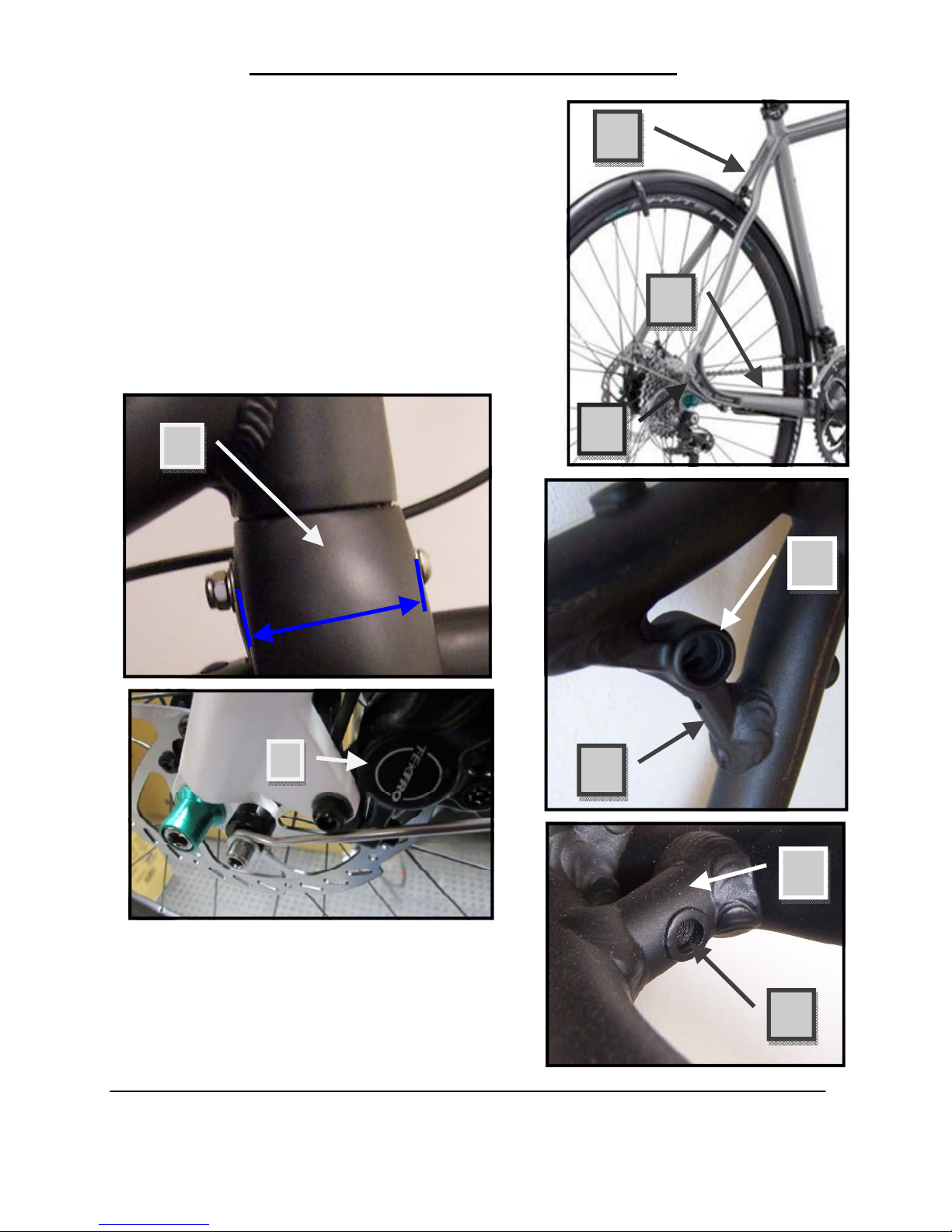
1. Front Fork Crown & Thickness.
2. Disc Brake Caliper.
3. Seat-stay.
4. Chain-stay.
5. Rear drop-out.
6. Seat-stay bridge.
7. Stepped seat-stay bridge hole.
8. Chain-stay bridge.
9. Threaded chain-stay bridge hole.
Side Stay Lengths:
300mm long for 46mm wide mudguards.
315mm long for 38mm wide mudguards.
1
1
2
7
6
8
9
3
4
5

WHYTE Mudguard Assembly Instructions
Mounting Hardware:
38mm Wide Mudguards
Description Reference Quantity
Button head cap-screw M5 x 25 long 26 1
Button head cap-screw M6 x 12 long 12 1
Button head cap-screw M6 x 30 long 16 1
Button head cap-screw M6 x 50 long 8 1
Button head cap-screw M6 x 60 long 8 1
Cap-screw M5 x 12 long 6 3
Cap-screw M5 x 16 long 21 4
Cap-screw M5 x 20 long 22 1
Cap-screw M6 x 65 long 8 1
Cycle brake nut M6 thread x 10mm long 18 1
Nut M6 Nylock 10 2
Spacer Ø6.2 hole x Ø15 outside x 5 long 23 2
Spacer Ø5.2 hole x Ø10 outside x 10 long 25 1
Washer Ø5 hole x Ø13 outside x 0.8 thick 7 13
Washer Ø6 hole x Ø12 outside x 1.6 thick 9 3
Washer Ø6 hole x Ø18 outside x 1.6 thick 17 1
Button head cap-screw M5 x 35 long 24 1
46mm Wide Mudguards
Description Reference Quantity
Button head cap-screw M6 x 12 long 12 2
Button head cap-screw M6 x 35 long 19 1
Cap-screw M5 x 12 long 6 2
Cap-screw M5 x 16 long 21 2
Cycle brake nut M6 thread x 10mm long 18 1
Nut M6 Nylock 10 2
Spacer Ø6.2 hole x Ø15 outside x 5 thick 23 1
Washer Ø5 hole x Ø13 outside x 0.8 thick 7 4
Washer Ø6 hole x Ø12 outside x 1.6 thick 9 3
Washer Ø6 hole x Ø18 outside x 1.6 thick 17 1

WHYTE Mudguard Assembly Instructions
Assembling the Front Mudguard:
• Reference figure A. Using a 3mm A/F Allen Key, undo the M4 screw
(1) in one stay bracket (2) by no more than one rotation. Clip the
stay bracket (2) onto the side of the front mudguard (3). Position
the stay bracket (2) approximately 100mm above the mudguard end.
Re-tighten the stay bracket screw according to the torque value
shown in the table on page 15.
15
11
14
4
2
4
4
A
1
0
0
m
m
3
5
0
m
m
Tab
1
0
0
m
m
2
1
5
3
WHYTE Mudguard Assembly Instructions
• Insert a single side-stay (4)
through the threaded sleeve
(5) and also into the end of the
stay bracket (2). Screw the
sleeve (5) into the end of the
stay bracket (2) and lightly
tighten. Repeat this process
for the other items (1, 2, 4 &
5) on the other side of the
mudguard (3). Do not firmly
tighten the sleeves (5) just yet,
as the side-stays (4) may need
to be adjusted later.
• Remove the front wheel from
the bicycle (refer to page 15 of
the Whyte General Instruction Manual on
how to do this).
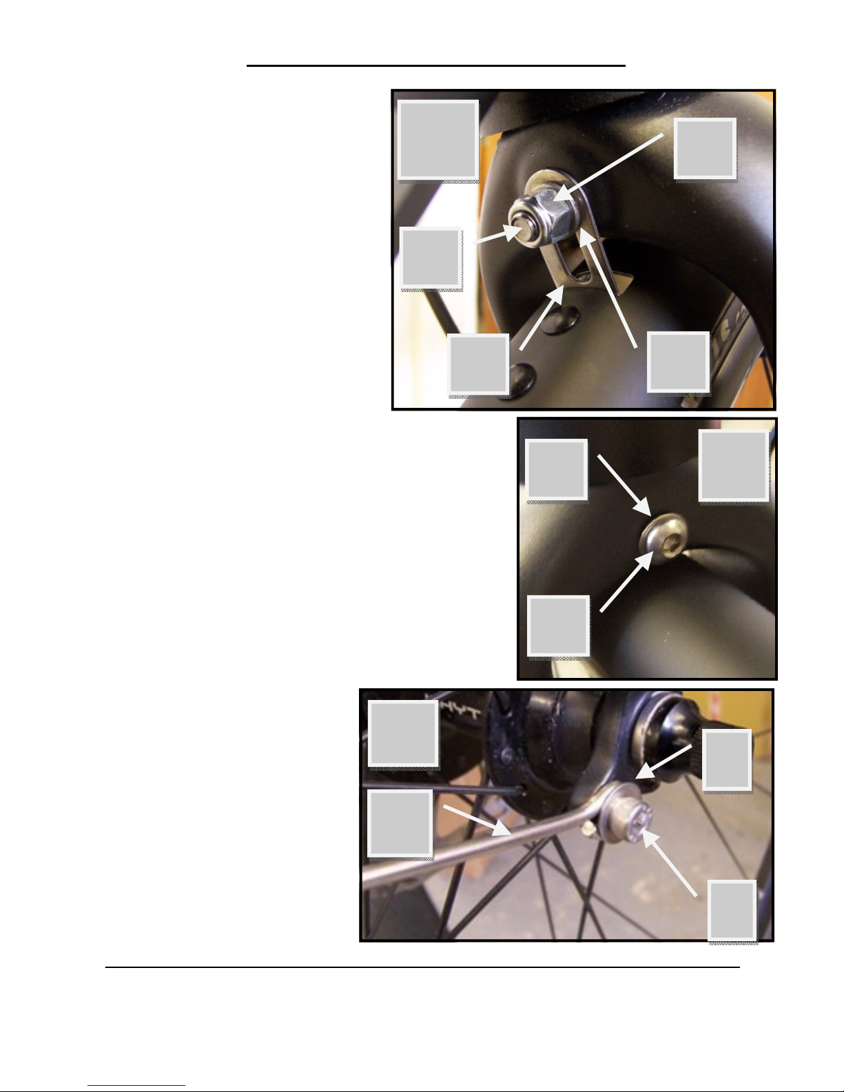
• For Rigid Forks
◊ Reference figures B & C. Depending on
the thickness of the front fork crown
(see Terminology), use either an M6 x
65 capscrew or an M6 x 60 long or 50
long button head cap-screw (8), plus
two small washers with Ø6 holes (9) and
an M6 Nylock hex nut (10) to attach the
bridge bracket (11) to the rear of the
crown of the front
fork.
◊ Reference figure D.
Using an M5 x 12
long cap-screw (6)
and a washer with a
Ø5 hole (7), attach
the looped end of the
side-stay (4) to the
threaded hole in each
of the front fork legs.
B
8
9
11
10
9
8
C
4
6
D
7
WHYTE Mudguard Assembly Instructions
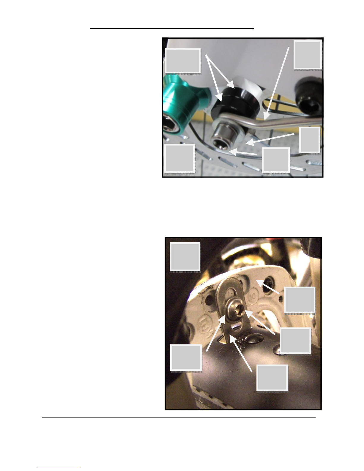
◊ Reference figure E. Us-
ing an M5 x 20 long
cap-screw (22), a
washer with a Ø5 hole
(7) & two 5mm thick
spacers (23), attach
the looped end of the
side-stay (4) to the
threaded hole in the
left front fork leg. For
the threaded hole adjacent to the axle, two
spacers (23) are required to allow the side
-stay (4) to clear the
disc brake caliper (see Terminology). Some other forks have a
t
hreaded hole further up the side of the fork. In this case no
spacers (23) are required.
• For Suspension Forks
◊ Reference figure F. Us-
ing an M6 x 12 long
button head cap-screw
(12) and a small washer with a Ø6 hole (9),
attach the bridge
bracket (11) to the rear
of the lower leg bridge
of the front fork (13).
4
22
E
7
23
F
12
11
13
9

WHYTE Mudguard Assembly Instructions
◊ Reference figure G.
Using an M5 x 12
long cap-screw (6)
and washer with a
Ø5 hole (7), attach
the looped end of
the side-stays (4)
to the threaded
holes in each of the
front fork legs.
• Refit the front wheel
(refer to page 15 of
the Whyte General
Instruction Manual on
how to do this).
• Carefully adjust all the fixing points until the mudguard sits evenly and
c
entrally around the front tyre, with a minimum clearance of 6mm.
Also check there is enough clearance from the mudguard to your foot
when in the pedal rotated fully forwards. Then tighten the fasteners
according to the torque values shown in the table on page 15.
Assembling the Rear Mudguard:
• Slide the bridge bracket (15) onto & around the outside of the rear
mudguard (14) with the tab towards the rear of the frame. Position
the bridge bracket (15) approximately 350mm above the forward
mudguard end (see Figure A on page 6). Check that it is a tight fit
on the mudguard (14).
• Reference figure A on page 6. Using a 3mm A/F Allen Key, undo the
M4 screw (1) in one stay bracket (2) by no more than one rotation.
Clip the stay bracket (2) onto the side of the bare rear mudguard
(14). Position the four stay brackets (2) approximately as shown in
image A, ie: the two lower stays approximately 100mm above the
mudguard end and the two upper stays approximately equal distances
between the mudguard end and the location of the bridge bracket
(15). Insert a side-stay (4) through the threaded sleeve (5) and also
G
4
6
7

WHYTE Mudguard Assembly Instructions
into the end of the stay bracket (2). Screw the sleeve (5) into the end
of the stay bracket (2) and lightly tighten. Repeat this process for the
other items (1, 2, 4 & 5) on
the other locations of the
mudguard (14). Do not firmly
tighten the sleeves (5) just
yet, as the side-stays (4) may
need to be adjusted later.
• Remove the rear wheel from
the bicycle (refer to page 15
of the Whyte General Instruction Manual on how to do
this).
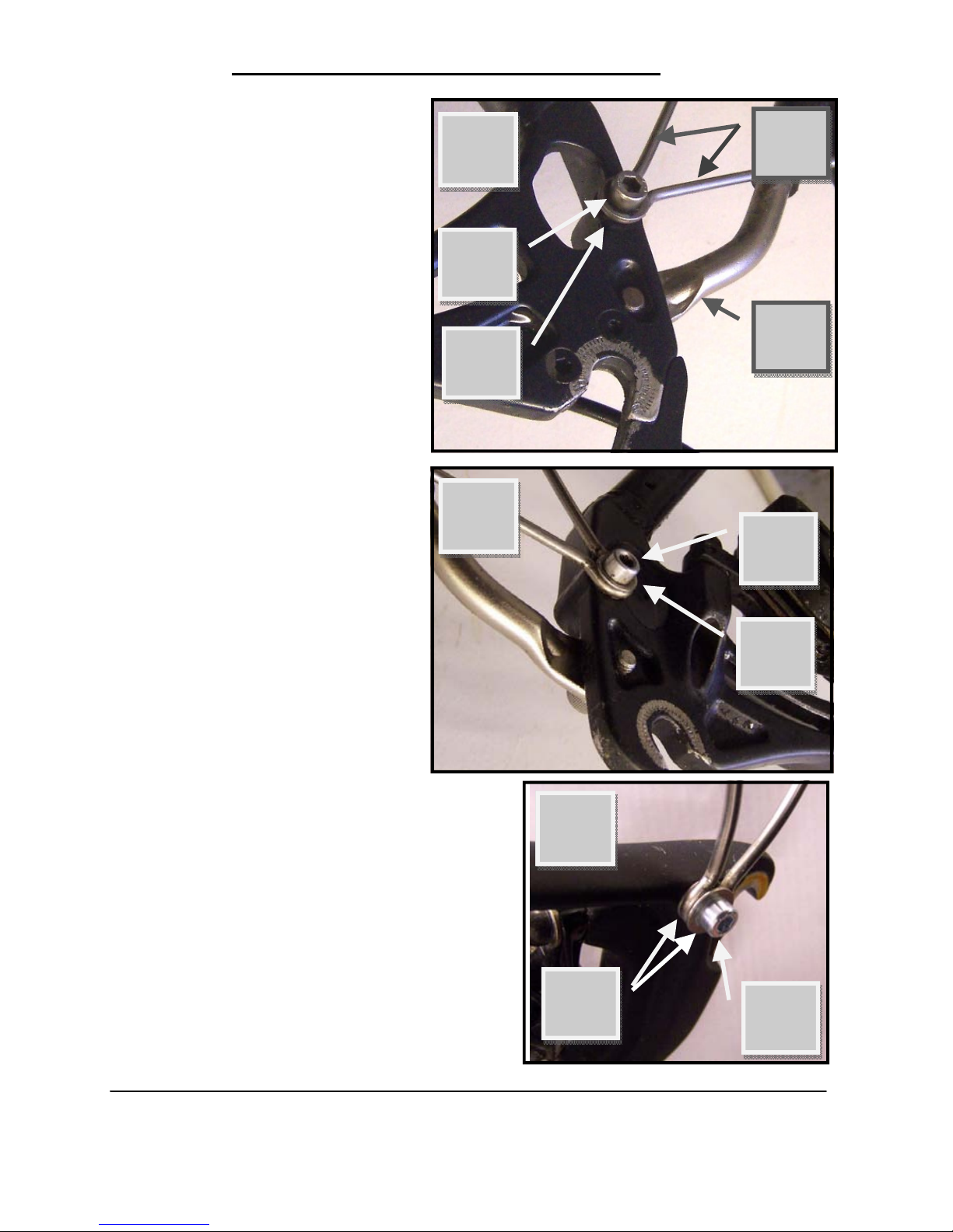
• Reference figures H & J. For a
f
rame without a step in the
seat-stay bridge hole (see
Terminology). Using an M6 x
30 long button head capscrew (16), a
small washer
with a Ø6 hole
(9), a large
washer with a
Ø6 hole (17)
and an M6 Nylock hex nut
(10), attach
the bridge
bracket (15)
to either the
front or rear
of the seatstay bridge
(see Terminolo
gy).
H
15
16
17
J
10
16
9
Tab

WHYTE Mudguard Assembly Instructions
• Reference figures
K & L. For a frame
with a step in the
seat-stay bridge
hole (see Terminol-
ogy). Using an M6
x 12 long button
head cap-screw
(12), a large
washer with a Ø6
hole (17) and an
M6 x 10 long cycle
brake nut (18),
attach the bridge
bracket (15) to
the rear of the
seat-stay bridge
(see Terminology).
K
L
12
17
15
18

WHYTE Mudguard Assembly Instructions
• Reference Figure M. For a
frame with an M5 rivet nut
in the rear of the seat-stay
bridge (eg: Cornwall). Slide
the bridge bracket (15) onto & around the outside of
the rear mudguard (14)
with the tab towards the
front of the frame. Using
an M5 x 16 long button
head cap-screw (21) and
two washers with a Ø5 hole
(7), attach the bridge
bracket (15) to the rear of
the seat-stay bridge (see
T
erminology). One washer
(7) should be placed either
side of the bridge bracket
(15).
• Reference figure N. For a
frame with a threaded
chain-stay bridge boss
(see Terminology). Using
an M5 x 12 long capscrew (6) and a washer
with a Ø5 hole (7), attach
the front end of the mudguard (14) to the threaded hole in rear of the
chain-stay bridge (see
Terminology).
M
7
14
6
N
7
21
15

WHYTE Mudguard Assembly Instructions
• Reference figure P. For a frame with
a non-threaded chain-stay bridge
boss (see Terminology). Using an M6
x 35 long button head cap-screw
(19), two small washers with Ø6
holes (9), a 5mm thick spacer (23)
and an M6 nylock hex nut (10), attach the front end of the mudguard
(14) to the open hole in the chainstay bridge (see Terminology). Use
the spacer between the bridge and
the mudguard to provide clearance
between the mudguard and the
front derailleur (see Terminology).
• Reference figure Q. For a
frame without a chain-stay
bridge, but which has a roller
for the front derailleur cable
(eg: 2013 Kings Cross or 2013
Charing Cross). Using an M5 x
35 long button head capscrew (24), a washer with a
Ø5 hole (7) & two 5mm thick
spacers (23), attach the front
end of the mudguard (14) to
the seat tube through the roller.
9
10
23
19
P
23
24
14
14
Q
WHYTE Mudguard Assembly Instructions
• Reference figures R & S
(showing the inside of each
rear drop-out. Q = right
side & R = left side). For
frames with two M5 threaded holes in each drop-out,
the side-stays (4) should be
mounted on the INSIDE of
rear drop-outs alongside the
M5 threaded holes. This will
allow a rear luggage carrier
(20) to be fitted to the bicycle alongside the M5 threaded holes further down the
drop-out.
Using an M5 x 16 long button head cap-screw (21) and
washer with a Ø5 hole (7),
attach the looped end of the
side-stays (4) to the threaded holes in each of the rear
drop-outs. Ensure that the
side-stays (4) are in the correct location on the mudguard (14) and then tighten
both M5 x 16 long button
head cap-screw (21) into
the drop-outs, BEFORE the rear
wheel is re-fitted.
Reference figure T. For frames with
one M5 threaded hole in each dropout, the side-stays (4) should be
mounted on the OUTSIDE of rear
drop-outs alongside the M5 threaded
holes. Also, for carbon fibre frames,
fit a washer with a Ø5 hole (7) to
both sides of each side-stay (4).
R
20
4
S
7
21
21
7
T
7
21

WHYTE Mudguard Assembly Instructions
• Reference figures U & V. For a frame with
an M5 rivet nut in the rear of the seat tube
(eg: Cornwall). Using an M5 x 25 long button head cap-screw (26), three washers
with a Ø5 hole (7) & a 10mm long spacer
(25), attach the front end of the mudguard
(14) to the seat tube. One washer (7) is
placed onto the head of the cap-screw
(26), then passed through the upper slot
in the mudguard. Then another washer
(7), the spacer (25) and the third washer
is placed onto the cap-screw (26) from the
outside of the mudguard. Then thread the
cap-screw (26) into the seat-tube rivet.
Tighten the cap-screw (26) BEFORE the
rear wheel is re-fitted.
• Refit the rear wheel (refer to page 15 of
t
he Whyte General Instruction Manual on
how to do this).
• Carefully adjust the remaining loose fixing points until the mudguard
(14) sits evenly and centrally around the rear tyre, with a minimum
clearance of 6mm. Then tighten the loose fasteners according to the
torque values shown in the table below.
1 M4 x 10 long cap-screw 2.5 Nm
1.8 lbs.ft
6, 21, 22, 24 or 26 M5 x 12/16/20/25/35
long screws
5.0 Nm
3.7 lbs.ft
8 M6 x 65/60/50 long screws 10 Nm
7.4 lbs.ft
12, 16 or 19 M6 x 12/30/35 long screws 5.0 Nm
3.7 lbs.ft
Item Description Torque
25
U
7
V
26
7
 Loading...