

Whyte bikes E-150, E-180 Operating Instructions And Owner's Manual


E-MTB Full Suspension Bike Range
Page 3 Whyte Supplementary Service Manual
Page 37 BOSCH Drive Unit
Page 45 BOSCH PowerTube Battery
Page 57 BOSCH Charger
Page 67 BOSCH Purion Display
Page 75 BOSCH Error codes


1.0 Introduction
2.0 Geometry
3.0 Preparations for riding:
3.1 Making Adjustments
3.2 Whyte Inter Grip Seat Clamp Adjustment
3.3 Set up of Fork
3.4 Set up of Rear Damper
3.5 Suspension Tuning Log
4.0 Safety.
5.0 Lubrication:
5.1 Whyte Inter Grip Seat Clamp
5.2 General Lubrication
6.0 Servicing the Rear Suspension:
6.1 Removing the Rear Shock and Swinging Arm.
6.1.1 Remove the Rear Shock only.
6.1.2 Remove the other rear suspension parts.
6.1.3 Remove the chain-stay & bearings from the Main Frame
6.2 Stripping and Re-assembling Other Rear Suspension Bearings
6.2.1 Extraction of Bearings
6.2.2 Insertion of Bearings
6.2.3 Re-Assembly of Shield Washers / Spacers
6.3 Re-assembling the Rear Suspension
6.3.1 Re-Assembly of the Rear Suspension.
6.3.2 Insert the bearings into the Main Frame, plus
assemble the chain-stays to the Main Frame.
6.3.3 Re-assemble the other rear suspension parts.
6.3.4 Re-assemble the Rear Shock into the Main Frame.
6.2.4: Application of “SKF LGAF 3E” or “Castrol Optimol T”
Anti-Fret Pastes.
7.0 Servicing the Whyte Modular Dropout Systems:
7.1 Disassembly of Modular Rear Dropouts.
7.1.1 Shimano E-Thru
7.1.2 SRAM Maxle 148mm
7.2 Reassembly of Modular Rear Dropouts.
7.2.1 Shimano E-Thru
7.2.2 SRAM Maxle 148mm
8.0 Servicing the Whyte Inter Grip Seat Clamp
Table of Contents
Page 3 2019

WHYTE Service Manual
9.0 Fitting Internal Cables & Hoses.
9.1 To replace cable or hose outers.
9.2 To fit a “Dropper” seat-post with internal cable.
10.0 Removal of Battery
10.1 Location of Bosch Battery On/Off Button.
10.2 Location of Bosch Battery Charge Port.
11.0 Torque Settings.
12.0 Owner’s Notes
Table of Contents (continued)
1.0: INTRODUCTION
Thanks for choosing to purchase this Whyte product. We hope you will enjoy all
the benefits its advanced design and engineering will bring to your riding experience.
This manual will guide you through the set-up, safety and maintenance procedures that are specific to your Whyte bike. For other more general information,
we strongly advise that you also read thoroughly the General Instruction Manual
that is also supplied with your new bike.
Also, please note that the specification of all the components that are fitted to
your bike as standard may be obtained from the Whyte Bikes Brochure or alternatively from the Whyte Bikes website www.whyte.bike
Please remember, if you are in any doubt about your ability to safely service or
repair your Whyte bike, do not ride it and instead arrange for a professional bicycle mechanic at your local Whyte dealer to do the job correctly.
Bundled with this manual, are the respective manufacturers instructions and
manuals for the branded parts and systems that are fitted to your Whyte bike.
Please take time to study all the relevant instruction manuals to ensure you have
a continually safe and well set-up bike before every ride, and to help you build up
a relationship of knowledge between you and your Whyte Dealer.
Happy and safe riding,
Whyte design team
2.0: GEOMETRY
The geometry of the full suspension range of Whyte Bikes is available from the
Whyte Bikes website www.whyte.bike
Page 4
2019

WHYTE Service Manual
3.0: PREPARATIONS FOR RIDING
3.1: MAKING ADJUSTMENTS
Please refer to the specific component
manufacturers manual or published technical information about adjusting, servicing or replacing the components on your
Whyte bike. Instructions may be downloaded from the relevant manufacturer’s
internet website, as shown in the table to
the right.
In addition, we recommend that you
should also read carefully the advice published by Bosch e-bike systems about
operation of the Bosch e-Bike systems
Bosch www.bosch-ebike.com
Crank
Brothers
DT Swiss www.dtswiss.com
Formula www.formulahubs.com
Fox www.foxracingshox.com
Joytech www.joytech.co.tw
Maxxis www.maxxis.com
Race Face www.raceface.com
SR Suntour www.srsuntour-cycling.com
www.crankbrothers.com
fitted to the Whyte e-MTB. Failure to do
so could result in Serious Injury or Death.
For additional advice on general care of e-
SRAM www.sram.com
WTB www.wtb.com
bikes, Visit:
www.bosch-ebike.com/en/news/care-of-ebikes/
CAUTION! If you are uncertain in any way, about making adjustments to
any components or systems on you Whyte bike, then DO NOT RIDE YOUR
BIKE. Contact your Whyte dealer who will be able to advise you on how to
go about setting up you Whyte bike for riding, and or making adjustments
to the components fitted to your Whyte bike.
3.2: WHYTE INTER GRIP SEAT CLAMP ADJUSTMENT & SERVICE
Tools Required: 5mm Hex Key
Torque Wrench (Ranging from 3Nm to 15Nm)
SKF LGEP2 or Castrol Spheerol AP3 or Finish Line Teflon White
Lithium
Complex grease
The Inter Grip seat clamp design is present on some models of Whyte full suspension mountain bikes. It allows adjustment of the saddle height & direction.
CAUTION! Avoid over-tightening the seat clamp.
In particular, “dropper” Seat Posts may not work correctly if the seat clamp
is over tightened.
Page 5 2019

WHYTE Service Manual
Ite
m
1
2
3
4
5
Description
Cap-screw, M6 x 30mm
Inter-Grip Sleeve,
threaded.
“O” Ring seal, fits in
sleeve groove.
Inter-Grip Sleeve, no
Inter-Grip Pad for
Ø30.9mm Seat Post.
long.
thread.
Fig.1: Inter-Grip Seat Clamp
To adjust the Seat height and/or direction, using the 5mm Hex Key, undo the M6
Capscrew (1) just enough to allow the Seat Post to slide freely up and down. Set the
height and/or direction to the desired level. Re-tighten the M6 Capscrew (1), using
the 5mm Hex Key and Torque Wrench, to the 14Nm limit, as marked on the Plain
Sleeve (4).
If a “dropper” Seat Post is fitted, simultaneously depress the activation trigger and
press down on the Saddle to compress the Seat Post until it is fully compressed. Then
release the activation trigger and the Seat Post should rise up automatically. If this
does not happen, gradually loosen the M6 Capscrew (1) with the %mm Hex Key below the 14Nm limit, until the Seat Post rises automatically. Then firmly twist the Saddle to confirm the Seat Post is still securely gripped by the lowered torque value that
allows the “dropper” Seat Post to function correctly.
CAUTION! When adjusting the saddle height you MUST obey the Minimum
insertion depth requirement marked on the Seat Post. Also consult the manufacturers Seat Post instructions in conjunction with these notes.
3.3: SET UP OF FORK
Tools Required: Good Quality Shock Pump.
Small Ruler
The Front Suspension Fork fitted to your Whyte bike will be pre-set with the standard
settings. Before riding, you may need to adjust these setting. First is the Sag setting
on the fork. This is to ensure the forks are set-up correctly for your own body weight,
allowing the fork to perform as intended.
To set Sag on the Fork, you need to measure the amount the Fork compresses when
you sit on the bike in the normal riding position.
Refer to the specification tables in the relevant Fork manufacturers set up instruc-
Page 6
2019

WHYTE Service Manual
tions to find how to adjust the air spring pressure. Using a Shock pump, either add
or remove air until Sag is correctly set.
Please note that for the detailed instructions for servicing and all matters relating
to the Forks fitted to your Whyte bike, please refer to the relevant manufacturers
instructions.
Rebound Damping adjustment:
This adjustment fine-tunes the speed at which the wheel returns to its normal ride
height after hitting a bump. Refer to the relevant manufacturers instructions to find
out how to adjust the rebound damping. To demonstrate the effect of this function,
turn the adjuster to its slowest setting. Press down on the handlebars to compress
the Forks, then release the load. The suspension recovers very slowly to its original
position.
Repeat the above with the adjuster turned to the fastest setting and the difference
will be seen immediately the load is released. We recommend the optimum setting
is to adjust the re-bound damping to be as slow as possible, but not so slow that
the normal ride height is not recovered. On very rough terrain, if the bike becomes
progressively lower as more bumps are hit then the re-bound damping is set too
slow. On the other hand if the bike feels choppy and not plush then the re-bound
damping is too fast. A bit of trial and error is needed to get the exact setting.
IMPORTANT SAFETY NOTE:
Always stop riding when making adjustments of
any kind to the bicycle!
3.4: SET UP OF REAR DAMPER
Tools Required: Good Quality Shock Pump.
Small Ruler
Your Whyte bike is fitted with either an air spring or a coil spring rear Shock. This
means that for an air Shock, the air pressure in the shock absorber determines the
spring rate and on a coil Shock, the rating of the spring determines the spring rate.
The correct ‘sag’ can be found using the sliding ‘O’ ring fitted to the shaft of the
Shock piston. Slide the ‘O’ ring against the Shock body. Then gently sit on the bike
in your normal riding position and with normal riding gear, including back pack if
applicable, and also raise your feet off the floor. Carefully dismount and measure
the distance the ‘O’ ring has moved away from the Shock body.
The optimum distance for the Quad-Link rear suspension system is shown in the
table to the right. If there is less than that distance fit a Shock pump and release
air pressure. Conversely if there is greater than that distance, fit the Shock pump
and increase air
Repeat the ‘sag’ test until the recommended sag distance is achieved.
For Coil Shock, the spring rate adjustment is made by swapping the spring for a
higher or lower rate spring. If more sag is required, swap the spring for a lower
Model Sag @ 30%
E-150
E-180 19.5mm
16.5mm
Page 7 2019

WHYTE Service Manual
rate spring. If less sag is required, swap the spring for a higher rate spring.
Rear Suspension Set-up - Rebound Damping:
When the damper unit is being compressed, this is known as the compression stroke.
As the suspension unit recovers from compression back towards its full length, this is
called the re-bound stroke. All the shocks fitted as standard to the Whyte full suspension mountain bikes have factory set compression damping, and manually adjustable
rebound damping.
Rebound Damping Adjustment:
The advice in section 3.3 about the fork rebound damping adjustments also applies to
the rear shock.
IMPORTANT SAFETY NOTE:
Always stop riding when making adjustments of any kind to the bicycle!
Platform Damping Adjustment.
The rear Shock fitted to your Whyte bike may have a “platform” facility to adjust the
slow speed compression damping, eg Fox “3pos w/Adj” or SRAM RockShox “Motion
Control”. Please refer to the relevant shock manufactures technical information to
learn how to adjust these features.
Please note, that the Whyte rear suspension systems have been designed not to rely
on excessive low speed compression damping to obtain efficient pedalling performance, and turning on too much low speed damping on the rear shock will compromise the suspensions sensitivity to small bump absorption and traction.
3.5: SUSPENSION TUNING LOG
Record your best suspension settings in the table below, to restore them if necessary,
eg. after dealer servicing of the suspension or if a friend has borrowed your bike.
Rider Weight
Date
(including all
riding kit)
(kg or lbs)
Fork Pres-
sure
(bar or P.S.I)
Fork Rebound
Damping
(# of clicks from
softest setting)
Shock Pressure
(bar or P.S.I)
Page 8
Shock Rebound
Damping
(# of clicks from
softest setting)
2019

WHYTE Service Manual
4.0: SAFETY
IMPORTANT: The following are intended to be advisory notes on the safe
use of your Whyte bike. You should also read thoroughly the General In-
struction Manual also supplied with your new bike. If at any stage you are
uncertain about the safety or safe operation of the bike as a whole, or any specific
component, then DO NOT RIDE YOUR WHYTE and instead please consult the
specific component manufacturers instruction manual or your Whyte Dealer for
advice.
Maximum Weight Limit:
18st. / 114kg (including rider’s pack and all riding equipment )
WARNING: As is the case with all mechanical components, the bicycle is
subjected to wear and high stresses. Different materials and components
may react to wear and stress fatigue in different ways. If the design life of a
component has been exceeded, it may fail suddenly causing possible injury
to the rider. Any form of crack, scratches and decolouring in high stress areas are showing that the component has exhausted its life time and has to be
replaced. If you are in any doubt about one or more components on your
Whyte DO NOT RIDE YOUR BIKE. Consult the specific component manufacturers literature, or take your bike to your local Whyte Dealer.
WARNING: Your Whyte eMTB has been fitted with a Bosch e-MTB e-bike
systems. We strongly recommend that you read, understand and adhere to
the instructions contained in the following Bosch manuals and literature:
• Remote Handlebar control unit
• Battery and Battery Charging
• Drive Unit
• E-Bike Care.
Failure to understand and operate the Bosch components correctly
could result in serious injury or death.
Designed for the following use:
The Whyte eMTB range of bicycles have all been designed, tested and comply with
EN-15194:2017 Safety Standard, for typical mountain biking use.
Page 9 2019
WHYTE Service Manual
5.0: LUBRICATION
Please refer to the Whyte General Instruction Manual for guidance about lubricating
many of the components on your Whyte bicycle.
For the range of bicycles contained in this Supplementary Service Manual, there is
also the following specific guidance:
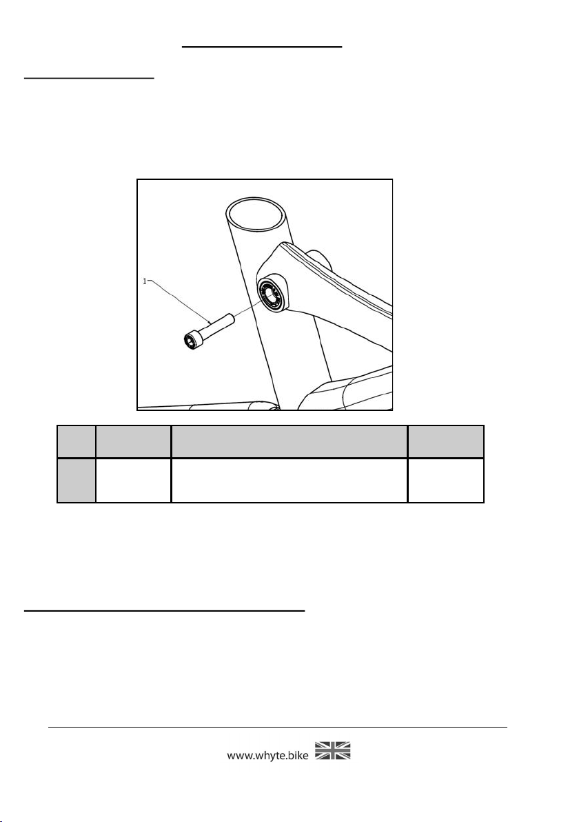
5.1: WHYTE INTER GRIP SEAT CLAMP
Figure 2: Capscrew Lubrication
Item Lubricant
Description
Lubrication
Interval
1
M6 x 30mm
Capscrew
SKF LGEP2 or Castrol Spherol AP3 or Finish
Line Teflon White Lithium Complex grease
Once a Month
5.2: GENERAL WHYTE LUBRICATION
For the correct lubrication regime and maintenance of all parts on a Whyte bicycle,
please refer to the specific component manufacturers detailed instructions bundled
with this manual or for further information visit the specific manufacturers website.
6.0: SERVICING THE REAR SUSPENSION
6.1: Remove the Rear Shock, Links & Swinging Arm:
Tools Required: 2x 4mm Hex Key
1x 5mm Hex Key - Ball ended
1x 6mm Hex Key
1x 8mm Hex Key
2x T-25 Torx® Keys
Page 10
2019

WHYTE Service Manual
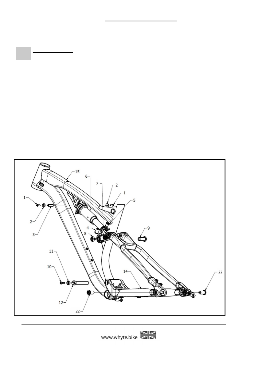
Item Description
1 M5 x 16mm long Socket-head Capscrew (T-25 Torx®)
2 Collar for M5 Capscrew
3 Hollow Pivot Pin Ø8mm x 31mm long
4 Flanged Nut M12 x 19mm long
5 Flanged Screw M12 x 15mm long
6 Rear Shock Absorber
7 Shock Extender
8 M15 x 26mm long Pivot Screw, 15mm Thread (6mm A/F Internal Hex)
9 M15 x 26mm long Pivot Screw, 15mm Thread (6mm A/F Internal Hex)
10 M6 x 20mm long Capscrew (5mm A/F Internal Hex)
11 Tapered Sleeve for Expanding Collet
12 Pivot Pin 80mm long, expanding collet, M15 thread.
13 M15 x 26mm long Pivot Screw, 10mm Thread (6mm A/F Internal Hex)
14 Chain-stays
15 Main Frame
16 Rear Suspension H Link, 99mm centre — to – centre
17 M15 x 25mm long Pivot Screw, 10mm Thread (6mm A/F Internal Hex)
18 Seat-stays
19 Shield Washer (O.D. 23mm)
20 Bearing (Enduro 6802-2RS-MAX)
21 Internal Spacer (49mm long)
22 M15 x 27mm long Pivot Screw, 14mm Thread (6mm A/F Internal Hex)
Page 11 2019
WHYTE Service Manual
6.1.1 To remove only the rear Shock (6) from the frameset
IMPORTANT: When removing Rear Shock and/or Seat & Chain stays al-
ways brace the rear end and Shock to prevent damage to frame when
weight is removed.
Whilst referencing figure 3, using the T-25 Torx® Keys, undo the two M5 x 16mm
long Socket-head Capscrews (1) from the Ø8mm x 31mm long Hollow Pivot Pin (3)
that passes through the Main Frame (15) and front of the Rear Shock (6). Whichever Capscrew (1) becomes undone first, remove it and the adjacent Collar (2),
and pull the Pivot Pin (3) all the way out from the other side.
Using the 6mm Hex Key and the 8mm Hex Key, undo and remove both the
Flanged Nut M12 x 19mm long (4) from the Flanged Screw M12 x 15mm long (5),
that pass through the Shock Extender (7) and the rear of the Rear Shock (6). You
can now remove the Rear Shock (6).
Figure 3: Disassembly of the
Rear Suspension (First Stage)
Page 12
2019

WHYTE Service Manual
Figure 4: Disassembly of the Rear Suspension (Third Stage)
6.1.2 To remove the Link (16) & Swinging Arm (14) from the Main Frame
(15).
Whilst referencing figure 3 & 4, using the 6mm Hex Key, unscrew and remove the
M15 x 26mm Flanged alloy Screws (8 and 9) from the front of the H Link (16).
Next, using the 6mm Hex Key, unscrew and remove the two M15 x 27mm Flanged
alloy Screws (22) at the rear of the Chain-stays (14). Be careful to retain all the
Shield Washers (Items 2 & 3, Figure 7) ready for re-assembly.
To separate the Seat-stays (18) from the H Link (16) and Main Frame (15), whilst
referencing figure 4, using the 6mm Hex Key, unscrew and remove the two M15 x
26mm Flanged alloy Screws (13) at the front of the Seat-stays (18). The Seatstays (18) may now be removed from the H Link (16). Finally to remove the Shock
Extender (7) from the H Link (16), using the 6mm Hex Key, unscrew and remove
the two M15 x 25mm Flanged alloy Screws (17). Be careful to retain all the Shield
Washers (Items 2 & 3, Fig 7) ready for re-assembly.
Page 13 2019

WHYTE Service Manual
6.1.3 To remove the Chain-stays (14) and Bearings (20) from the Main
Frame (15).
Whilst referencing figure 5, using the 5mm Hex Key, partially unscrew the M6 x
20mm long Capscrew (10) from the Pivot Pin 80mm long, expanding collet, M15
thread (12). Using the 6mm Hex Key, unscrew and remove the Pivot Pin 80mm
long, expanding collet, M15 thread (12). The capscrew (10) may now be completely
removed, to allow the tapered sleeve (11) to be released from the collet (12).
The Chain-stays (14) may now be removed from the Main Frame (15). Be careful to
retain the two Shield Washers (19) ready for re-assembly.
Using the press tools shown in Figure 19, extract the BOLU-WB0025
bearings (20) from both sides of the Main Frame (15). Align the removal tool carefully with the slots in the Spacer (21).
Page 14
Figure 5: Disassembly of the
Rear Suspension (Third Stage)
2019
6.2: STRIPPING AND REASSEMBLING OTHER BEARINGS.
(Reference figures 6 & 7)
WHYTE Service Manual
Figure 6: Assembly of Link
Item Description
1
2 Shield washer (O.D. 20mm)
3 Shield washer (O.D. 23mm)
4 Various centre-to-centre dimensions Alloy Link Bodies
ID 15mm, OD 24mm, Width 5mm, bearing
(BOLU-WB0025)
Page 15 2019
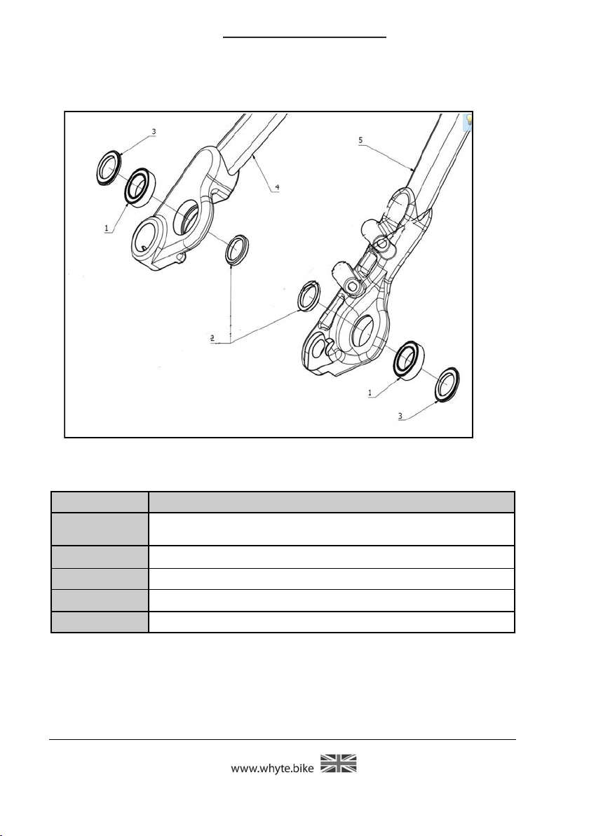
Figure 7: Assembly
of the Seat-stays
WHYTE Service Manual
Item Description
1
2 Middle shield washer (O.D. 20mm)
3 Outer shield washer (O.D. 23mm)
4 Right Seat-stay
5 Left Seat-stay
ID 15mm, OD 24mm, Width 5mm, bearing
Page 16
(BOLU-WB0025)
2019
WHYTE Service Manual
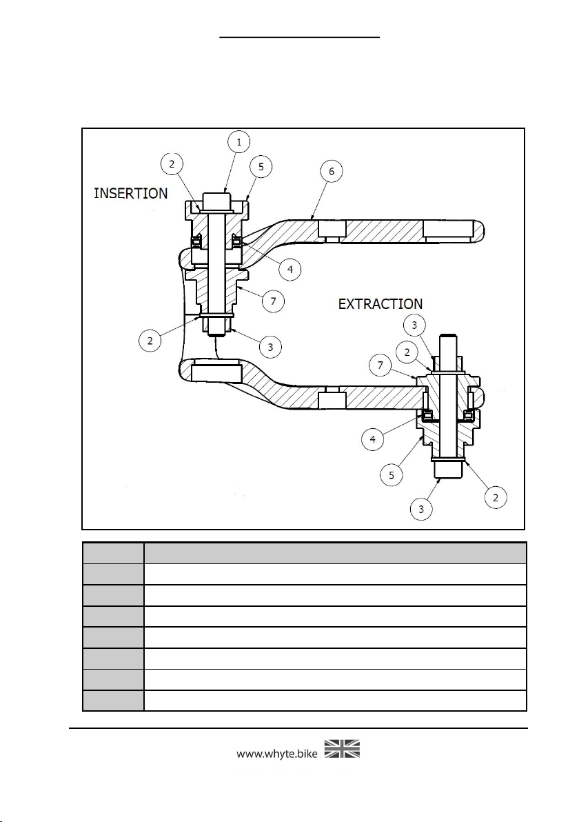
Figure 8: Bearing Insertion & Extraction 6802-2RS-MAX
(Link or Rear of Seat Stay)
Item: Description.
1 M8 Capscrew ISO4162 55 long
2 M8 Washer ISO 7089
3 M8 Nut ISO 4032
4 BOLU-WB0025 Bearing
5 BOLU-WB0025 Bearing Tool 1
6 Mating Component (ie: Link or Seat-Stay)
7 BOLU-WB0025 Bearing Tool 2
Page 17 2019
WHYTE Service Manual
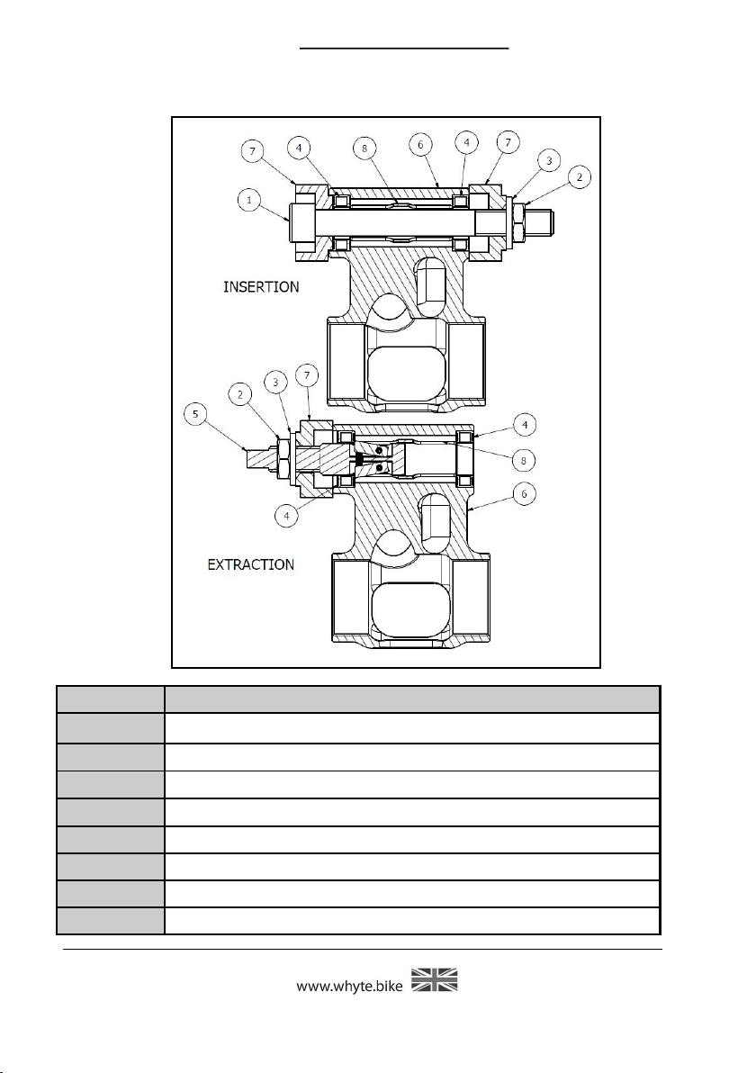
Figure 9: Bearing Insertion & Extraction 6802-2RS-MAX
(Above Main Frame Bottom Bracket)
Item: Description.
1 M8 Capscrew ISO4762 55 long
2 M12 Nut ISO 4035
3 I. D. 12 Washer ISO 7089
4 BOLU-WB0025 Bearing
5 BOLU-WB0025 Bearing Tool 1
6 Mating Component (ie: Bottom Bracket Yoke)
7 BOLU-WB0025 Bearing Tool 2
8 Internal Bearing Spacer
Page 18
2019

WHYTE Service Manual
6.2.1: EXTRACTION OF BEARINGS
Tools required: Either 6802-2RS-MAX or 15268-2RS_MAX Bearing press tool
6mm Hex Key
10mm Hex Key
13mm A/F Spanner
18mm A/F Spanner
To remove the Bearings (4) from the Link or Rear of the Seat-stay (6). Assemble
the parts as shown in figure 8. Using the 6mm Hex Key and 13mm spanner, tighten the assembly together until the Bearing (4) is pressed out of the mating component (6). Repeat on all other Bearings.
To remove the Bearings (4) from the Bottom Bracket Yoke (6). Assemble the
parts shown in figure 9. Using the 10mm Hex Key and 18mm spanner, tighten
the assembly together until the Bearing (4) is pressed out of the mating component (6). Repeat on all other Bearings.
6.2.2: INSERTION OF BEARINGS
Tools required: Either 6802-2RS-MAX or 15268-2RS-MAX Bearing press tool
6mm Hex Key
10mm Hex Key
13mm A/F Spanner
18mm A/F Spanner
Loctite 638
Before inserting the Bearings, make sure all the components are clean from dirt
and have been thoroughly de-greased. To press the Bearings (4) into the mating
component (6) apply a small amount of Loctite 638 to the outside diameter of the
Bearing and to the inside bore of the mating component (6). Next assemble the
components as illustrated in either Figure 8, or 9. It is very important to make
sure the Bearing (4) and Bearing Insertion tool 1 (5) are squarely seated against
the mating component (6). With great care, slowly tighten the M8 Socket head
cap screw (6) with the 6mm Hex Key and the nut (2) with the 13mm Spanner
until you can see the Bearing (4) being pressed squarely into the mating component (6). For the assembly shown in figure 9, use the 10mm Hex Key & the
18mm A/F Spanner. Once the Bearing is fully seated an you can no longer tighten
either the M8 or M12 Socket Head Cap Screws further, undo the nut and bolt and
remove any excess Loctite from around the Bearing, particularly in any internal
threads. Repeat for the remaining Bearings.
IMPORTANT! Allow 24 hours for the Loctite to totally cure.
6.2.3: REASSEMBLY OF SHIELD WASHERS / SPACERS
Tools required: SKF LGEP2 or Castrol Spherol AP3 or Finish Line Teflon
White Lithium
Complex grease
SKF LGAF 3E” or “Castrol Optimol T” Anti-Fret Paste
Apply a good quantity of SKF LGEP2 or Castrol Spherol AP3 or Finish Line Teflon
White Lithium-Complex grease on top of the Bearings. The grease should completely cover each Bearing and be applied on both sides of each Bearing when it is
in the Swinging arm component.
Page 19 2019

WHYTE Service Manual
Assemble the Shield Washer components (Items 19 in figure 5 or items 2 or 3 in figures 6 & 7). If you have applied enough grease, it should spread from under the
Shield Washer or Spacer components as they are positioned. Wipe this excess grease
away from around the Shield Washer or Spacer components.
6.2.4: Application of “SKF LGAF 3E” or “Castrol Optimol T” Anti-Fret Pastes
Once the H Link & Swinging Arm components have been assembled correctly, either
SKF LGAF 3E or Castrol Optimol T paste must be applied to all outside faces of the
Shield Washer components (Items 2 & 3 in Figures 6 & 7) that contact the Main
Frame and Swinging Arm. It is additionally recommended to apply anti-fret paste to
the mating contact surfaces on the Main
Frame and Swinging Arm.
6.3: RE-ASSEMBLING THE REAR SUSPENSION.
Figure 10: Correct
Orientation
6.3.1: Re-assemble the Rear Suspension
Tools Required: 2x 5mm Hex Key
2x 6mm Hex Key
2x T-25 Torx® Key
Torque Wrench
(Ranging from 5Nm to
25Nm)
Reference figures 3,4,5,6 & 10. The re-assembly of the Rear Suspension is essentially the reverse of the dis-assembly procedures 6.1.1, 6.1.2 & 6.1.3.
6.3.2 To re-assemble the Chain-stays (14) and Bearings (20) into the Main
Frame (15) - First Stage.
Before inserting the Bearings, make sure all the components are clean from dirt and
have been thoroughly de-greased. Apply a small amount of Loctite 638 to the outside diameter of the Bearing and to the inside mating bore of the Main Frame (15).
Using the press tools shown in Figure 8 & 9, insert the BOLU-WB0025 Bearings (20)
into both sides of the Main Frame (15). Ensure the spacer (21) is located between
the Bearings (20).
Referencing figure 5, apply either SKF LGAF 3E or Castrol Optimol T paste to all
faces of the Shield Washers (19), Pivot Pin (12) and Screw (10). Place the Shield
Washers (19) alongside the Bearings (20). Insert & align the Chain-Stays (14) between the Washers (19). Insert the Pivot Pin (12) from the left side of the ChainStays (14). Screw the Pivot Pin (12) io the thread in the right side of the ChainStays (14). Insert the Tapered Sleeve (11) and screw in the M6 x 20mm long Capscrew (10).
Page 20
2019

WHYTE Service Manual
6.3.3: To re-assemble the H Link (16), Shock Extender (7) & Seat-stay
(18) onto the Main Frame (15) - Second & Third Stages.
IMPORTANT: Prior to reassembly of the Seat-stay (18) to the H Link (16),
make sure the Seat tube of the Main Frame (15, not shown for clarity) is
inside of the assembly, as in figure 3. Also make sure the H Link is correct
side up, as per figure 10.
Starting with the Seat-stay (18) and the H Link (16), reference figure 4, first check
that the Shield Washers are in place in the H Link (see items 2 & 3 in figure 6) and
apply either SKF LGAF 3E or Castrol Optimol T anti-fret paste to the contacting
faces between the Shield Washers and Seat-stay (18). Then ensure that the Shield
Washers in the H Link (16) are not pushed out, as you place the Seat-stay (18)
inside it. Then pass an M15 x 26mm long Flanged alloy Screw (13) through the
right side of the Seat-stay (18), the adjacent Shield Washers (items 2 & 3, figure
6), and the Bearing in the H Link (16). Using the 6mm Hex Key, Torque tighten
the M15 Flanged alloy Screw (13) to the recommended Torque settings (refer to
the Tightening Torque settings in Section 10.0). Repeat that task to assemble the
left side of the Seat-stay (18) to the H Link (16), also ensuring that the other
Shield Washer in the H Link (16) is not pushed out.
Next, to assemble the Shock Extender (7) and the H Link (16), reference figure 4
(Main Frame 15 not shown for clarity), first check that the Shield Washers are in
place in the Link (see items 2 & 3 in figure 6) and apply either SKF LGAF 3E or
Castrol Optimol T anti-fret paste to the contacting faces between the Shield Washers and Shock Extender (7). Then ensure that the Shield Washers in the Link (16)
are not pushed out, as you place the Shock Extender (7) inside them. Then pass
an M15 x 25mm long Flanged alloy Screw (17) through the H Link (16), the Bearing in Link (See item 1, figure 6), the adjacent Shield Washer & into the thread of
one arm of the Shock Extender (7). Using a 6mm Hex Key, Torque tighten the
M15 Flanged alloy Screw (17) to the recommended Torque settings (refer to the
Tightening Torque settings in Section 10.0). Repeat that task to assemble the other
arm of the Shock Extender (7) to the H Link (16), also ensuring that the other
Shield Washer in the H Link (16) is not pushed out.
Next, to assemble the Link (16) to the Main Frame seat tube (15), reference figures 3 & 4, check that the Shield Washers are in place on the inside of the bearings
that are installed in front of the Link (16), reference figure 6, item (2) and apply
either SKF LGAF 3E or Castrol Optimol T anti-fret paste to the contacting faces between those shield washers and the Link mounting on the Main frame seat tube
(15). Insert the Link (16) between the Main Frame Seat tube (15). Then pass one
M15 x 26mm long Flanged alloy Screw (8 & 9) through the Link (16), the Bearing
in Link (1, figure 6), the adjacent Shield Washer & into the threaded Main Frame
(15). Screw in, from the left side of the H Link (16), the other M15 x 26mm long
Flanged alloy Screw (8) . Using a 6mm Hex Key, Torque tighten the M15 Flanged
alloy Screws (8 & 9) to the recommended Torque settings (refer to the Tightening
Torque settings in Section 10.0). Wipe off any excess grease from around the Main
Frame (15) and the H Link (16).
Finally to assemble the Chainstays (14) to the Seat-Stays (18), reference figure
18, check that the Shield Washers are in place on both sides of each Seat-stay leg
(18) (see items 2 & 3 in figure 6) and apply either SKF LGAF 3E or Castrol Optimol
Page 21 2019

WHYTE Service Manual
Using a 6mm Socket, first Torque tighten the right side of the Pivot Pin (12), to the
recommended Torque settings (refer to the Tightening Torque settings in Section
10.0). Then tighten the M6 x 20mm long Capscrew (10), again to the recommended Torque settings (refer to the Tightening Torque settings in Section 10.0). Wipe
off any excess grease from around the Chain-Stays and Seat-Stays.
6.3.4 To re-assemble the Rear Shock (6) into the Frameset.
Reference figure 17. Take the Rear Shock (6) and apply either SKF LG/AF 3E or
Castrol Optimol T anti-fret paste onto the side faces of the Shock Bushes, that contact the Main Frame (15) and Shock Extender (7). Slide the front of the Rear Shock
(6) into the Main Frame (15) and Shock Extender (7).
IMPORTANT. Ensure the damper is the correct way up, with any dials and
levers facing downwards and towards the front of the frameset, reference figure 10.
First make sure that the 12mm holes in the Shock Extender (7) line up with the rear
end of the Rear Shock (6). Insert the Flanged Nut M12 x 19mm long (4) & screw in
the Flanged Screw M12 x 15mm long (5). Using the 6mm Hex Key and the 8mm
Hex Key, Torque tighten the Flanged Nut M12 x 19mm long (4) into the Flanged
Screw M12 x 15mm long (5), to the recommended Torque settings (refer to the
Tightening Torque settings in Section 10.0). Wipe off any excess grease from
around both ends of the Shock (6).
Make sure that the Ø8mm holes in the Main Frame (15) and the front of the Rear
Shock (6) are all concentric with each other, and push the Ø8mm x 31mm long Hollow Pivot Pin (3) all the way through. Place a Collar (2) over both ends of the Ø8mm
x 31mm long Hollow Pivot Pin (3) and screw in an M5 x 16mm long Socket-head Cap
-screw (1) into both ends of the Pivot Pin (3). Using the T-25 Torx® Keys, Torque
tighten the M5 Cap-screws to the recommended Torque settings (refer to the Tightening Torque settings in Section 10.0).
7.0: SERVICING THE WHYTE MODULAR DROPOUT SYSTEMS.
7.1: Removing the Modular Rear Dropouts
Tools Required: 2mm Hex Key
3mm Hex Key
4mm Hex key
These Rear Drop-outs are a modular design, that can either be replaced if damaged
or converted to one of two different types of through-axle products, ie: Shimano EThru or SRAM Maxle 148mm. Contact your local Whyte dealer to purchase either a
replacement hanger or a conversion kit.
7.1.1: Shimano E-Thru System
Reference figure 11. The Rear Derailleur Hanger (2) is attached to the Right Side of
the Seat-stay (18) by one Countersunk M4 Cap Screw (1). To remove the Rear Derailleur Hanger (2), using the 3mm Hex Key undo that Cap Screw (1) and remove it
Page 22
2019

WHYTE Service Manual
together with the Rear Derailleur Hanger (2). Also, to remove the Adjuster (4),
using the 2mm Hex Key undo the Grub Screw (3) and remove it together with the
Adjuster (4). Take care not to loose any of the components.
7.1.2: SRAM Maxle 148mm “Boost” System
Reference figure 12. The Rear Derailleur Hanger (4) is attached to the Right Side
of the Seat-stay (18) by one M4 Countersunk Cap Screw (3). To remove the Rear
Derailleur Hanger (4), using the 3mm Hex Key undo that Cap Screw (3) and remove it, together with the Rear Derailleur Hanger (4). To remove the Axle Nut (6),
using the 2mm Hex Key undo the Grub Screw (5) and remove it, together with the
Axle Nut (6). Moving across to the Left Side of the Seat-stay (18), again using the
4mm Hex Key undo the M5 Countersunk Cap Screw (2) and remove it, together
with the Drop-out Spacer (1), from the assembly. Take care not to loose any of
the components.
7.2: Re-assembling the Modular Rear Dropouts onto the Swinging Arm
Tools Required: 2mm Hex Key
3mm Hex Key
Torque Wrench (Ranging from 1Nm to 5Nm)
It is important to make sure that all components are clean and free from mud, old
grease and other dirt, which could prevent them from fitting together perfectly.
7.2.1: Shimano E-Thru System
Reference figure 11. Loosely assemble all the parts as shown, making sure the
screws (1) & (3) are correctly positioned, be very careful not to cross-thread
this, on it’s way in. Insert the Rear Wheel and the Shimano E-Thru Rear Axle.
Adjust the Axle as per the Shimano Technical Service Instructions SI-27U0A-001-
00. Whilst adjusting the Rear Axle, make sure the nose of the M5 Grub Screw (3) is
aligned with one of the slots in the Axle Nut (4). Having tightened the Rear Axle,
using the Torque Wrench, tighten the M5 Grub Screw (3) to the correct Torque as
specified in Section 10.0. DO NOT OVERTIGHTEN, since the thread of the Screw
(1) is very small.
Remove the Rear Wheel and using the Torque Wrench, tighten the M4 Countersunk
Head Screw (1) to the correct torque as specified in Section 10.0. DO NOT OVER-
TIGHTEN, since the thread of the Screw (1) is very small.
7.2.2: SRAM Maxle 148mm “Boost” System
Reference figure 12. Loosely assemble all the parts as shown, making sure the
Screws (2), (3) & (5) are correctly positioned, be very careful not to cross-
thread these, on their way in. Insert the Rear Wheel and the SRAM Maxle, as
per the SRAM User Manual 95-4315-004-000. Whilst tightening the SRAM Maxle,
make sure the nose of the M5 Grub Screw (5) is aligned with the single slot in the
Axle Nut (6). Using the Torque Wrench, tighten the M5 Grub Screw (5) to the correct Torque as specified in Section 10.0. . DO NOT OVERTIGHTEN, since the
thread of the Screw (5) is very small.
Page 23 2019
 Loading...