

Whyte T-129 Works, G-150 S SCR, T-130 Works SCR, T-130 S Women’s Spec, T-129 Works SCR Supplementary Service Manual
...
G-150 Works SCR & G-150 S SCR
T-130 Works SCR, T-130 S &
T-130 SX Women’s Spec
T-129 Works SCR, T-129 Works
& T-129 S
M-109C Team & M109C S
Supplementary Service Manual
2015 Edition 1


Page 3 2015 Edition 1
Table of Contents
1.0 Introduction
2.0 Geometry:
2.1 G-150 Works SCR & G-150 S SCR
2.2 T-130 Works SCR, T-130 S & T-130 SX Women’s Spec.
2.3 T-129 Works SCR
2.4 T-129 Works & T-129 S
2.5 M-109C Team & M-109C S
3.0 Preparations for riding:
3.1 Making Adjustments
3.2 Whyte Inter Grip Seat Clamp Adjustment
3.3 Set up of Fork
3.4 Set up of Rear Damper
3.5 Suspension Tuning Log
4.0 Safety.
5.0 Lubrication:
5.1 Whyte Inter Grip Seat Clamp
5.2 General Lubrication
6.0 Servicing the Rear Suspension:
6.1 Removing the Rear Shock and Swinging Arm
6.1.1 From G-150
6.1.1.1 Remove the Rear Shock only.
6.1.1.2 Remove the other rear suspension parts.
6.1.2 From T-130, T-129 or M-109C
6.1.2.1 Remove the Rear Shock only.
6.1.2.2 Remove the other rear suspension parts.
6.2 Stripping and Re-assembling Rear Suspension Bearings
6.2.1 Extraction of Bearings
6.2.2 Insertion of Bearings
6.2.3 Re-Assembly of Shield Washers / Spacers
6.3 Re-assembling the Rear Suspension
6.3.1 Re-Assembly of the Rear Suspension (G-150)
6.3.1.1 Re-assemble the other rear suspension parts.
6.3.1.2 Re-assemble the Rear Shock into the Frameset.
6.3.2 Re-Assembly of Rear Suspension (T-130, T-129 or
M-109C)
6.3.2.1 Re-assemble the other rear suspension parts.
6.3.2.2 Re-assemble the Rear Shock into the Frameset.

Page 4
2015 Edition 1
1.0: INTRODUCTION
Thanks for choosing to purchase this Whyte product. We hope you will enjoy all the benefits
its advanced design and engineering will bring to your riding experience.
This manual will guide you through the set-up, safety and maintenance procedures that are
specific to your Whyte bike. For other more general information, we strongly advise that
you also read thoroughly the General Instruction Manual that is also supplied with your new
bike.
Also, please note that the specification of all the components that are fitted to your bike as
standard may be obtained from the Whyte Bikes Brochure or alternatively from the Whyte
Bikes website www.whytebikes.co.uk
Please remember, if you are in any doubt about your ability to safely service or repair your
Whyte bike, do not ride it and instead arrange for a professional bicycle mechanic at your
local Whyte dealer to do the job correctly.
Bundled with this manual, are the respective manufacturers instructions and manuals for
the branded parts that are fitted to your Whyte bike. Please take time to study all the relevant instruction manuals to ensure you have a continually safe and well set-up bike before
every ride, and to help you build up a relationship of knowledge between you and your
Whyte Dealer.
Happy and safe riding,
Whyte design team. April 2014.
WHYTE Service Manual
7.0 Servicing the Whyte Modular Dropout Systems:
7.1 Disassembly of Modular Rear Dropouts
7.1.1 Shimano E-Thru
7.1.2 SRAM Maxle 142mm
7.2 Reassembly of Modular Rear Dropouts
7.2.1 Shimano E-Thru
7.2.2 SRAM Maxle 142mm
7.3 Rear Derailleur Set-up
8.0 Servicing the Whyte Inter Grip Seat Clamp
9.0 Fitting Internal Cables & Hoses.
9.1 To replace cable or hose outers.
9.2 To fit a “Dropper” seat-post with internal hose.
10.0 Torque Settings.
Table of Contents (continued)
Page 5 2015 Edition 1
WHYTE Service Manual
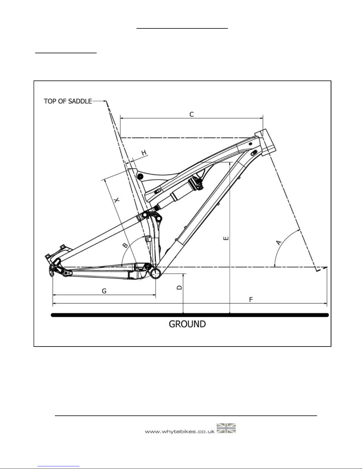
2.0: GEOMETRY
Figure1: Geometry

Page 6
2015 Edition 1
WHYTE Service Manual
Frame Size X Small Medium Large
Head Angle A 67.0° 67.0° 67.0°
Seat Angle* B 74.7° 74.5° 74.3°
Top Tube C 594.0mm 608.3mm 627.8mm
BB Height** D 342.5mm 342.5mm 342.5mm
Stand Over E 808mm 816mm 822mm
Wheel Base F 1154.3mm 1169.3mm 1189.3mm
Chain Stay G 425mm 425mm 425mm
Seat Post H 30.9mm 30.9mm 30.9mm
2.1: Whyte G-150 Geometry
Notes:
G
eometry shown here is ’Showroom’ i.e. without rider aboard the bicycle. ’With Sag’ geometry is with rider after correct
sag is set at front and rear. Please refer to suspension set up for information on how to achieve the correct sag of the
fork and rear damper.
* Effective seat angle, from wheel centres horizontal to line from BB to seat post axis @ top of saddle.
** BB height with Ø717mm tyres fitted (2.25” / 54-584)
Frame Size X Small Medium Large
Head Angle A 67.5° 67.5° 67.5°
Seat Angle* B 73.8° 73.5° 73.3°
Top Tube C 573.8mm 593.6mm 608.5mm
BB Height** D 331.0mm 331.0mm 331.0mm
Stand Over E 763mm 766mm 776mm
Wheel Base F 1112.4mm 1132.4mm 1148.4mm
Chain Stay G 420mm 420mm 420mm
Seat Post H 30.9mm 30.9mm 30.9mm
Extra Small
67.5°
74.1°
548.9mm
331.0mm
761mm
1087.4mm
420mm
30.9mm
2.2: Whyte T-130 Geometry
Notes:
Geometry shown here is ’Showroom’ i.e. without rider aboard the bicycle. ’With Sag’ geometry is with rider after correct
sag is set at front and rear. Please refer to suspension set up for information on how to achieve the correct sag of the
fork and rear damper.
* Effective seat angle, from wheel centres horizontal to line from BB to seat post axis @ top of saddle.
** BB height with Ø717mm tyres fitted (2.25” / 54-584)

Page 7 2015 Edition 1
2.3: Whyte T-129 Works & T-129 S Geometry
Frame Size X Small Medium Large
Head Angle A 68.0° 68.0° 68.0°
Seat Angle* B 74.3° 74.0° 73.8°
Top Tube C 575.5mm 595.5mm 610.3mm
BB Height** D 342.5mm 342.5mm 342.5mm
Stand Over E 805mm 808mm 813mm
Wheel Base F 1125.4mm 1145.4mm 1160.4mm
Chain Stay G 431mm 431mm 431mm
Seat Post H 30.9mm 30.9mm 30.9mm
Extra—Large
68.0°
73.5°
625.1mm
342.5mm
818mm
1175.4mm
431mm
30.9mm
WHYTE Service Manual
Notes:
Geometry shown here is ’Showroom’ i.e. without rider aboard the bicycle. ’With Sag’ geometry is with rider after correct
sag is set at front and rear. Please refer to suspension set up for information on how to achieve the correct sag of the
fork and rear damper.
* Effective seat angle, from wheel centres horizontal to line from BB to seat post axis @ top of saddle.
** BB height with Ø748mm tyres fitted (29” x 2.25” / 54/56-622)
2.4: Whyte T-129 Works SCR Geometry
Frame Size X Small Medium Large
Head Angle A 68.0° 68.0° 68.0°
Seat Angle* B 74.3° 74.0° 73.8°
Top Tube C 597.4mm 617.4mm 637.3mm
BB Height** D 335mm 335mm 335mm
Stand Over E 800mm 805mm 810mm
Wheel Base F 1145.4mm 1165.4mm 1185.4mm
Chain Stay G 431mm 431mm 431mm
Seat Post H 30.9mm 30.9mm 30.9mm
Extra—Large
68.0°
73.5°
657.1mm
335mm
815mm
1205.4mm
431mm
30.9mm
Notes:
Geometry shown here is ’Showroom’ i.e. without rider aboard the bicycle. ’With Sag’ geometry is with rider after correct
sag is set at front and rear. Please refer to suspension set up for information on how to achieve the correct sag of the
fork and rear damper.
* Effective seat angle, from wheel centres horizontal to line from BB to seat post axis @ top of saddle.
** BB height with Ø748mm tyres fitted (29” x 2.25” / 54/56-622)

Page 8
2015 Edition 1
WHYTE Service Manual
3.0: PREPARATIONS FOR RIDING
3.1: MAKING ADJUSTMENTS
Please refer to the specific component manufacturers manual or published technical information
about adjusting the components on your Whyte
bike. Instructions may be downloaded from the
relevant manufacturer’s internet site, as shown
in the table to the right.
CAUTION! If you are uncertain in any
way, about making adjustments to any
components on you Whyte bike, then DO
NOT RIDE YOUR BIKE.
Contact your Whyte dealer who will be able to
advise you on how to go about setting up you
Whyte bike for riding, and or making adjustments to the components fitted to your Whyte
bike.
DT Swiss www.dtswiss.com
Easton www.eastonbike.com
Ergon www.ergon-bike.com
Fi:zik www.fizik.it
Fox www.foxracingshox.com
Jagwire www.jagwireusa.com
Maxxis www.maxxis.com
Prologo www.prologotouch.com
Race Face www.raceface.com
Shimano www.shimano.com
SR Suntour www.srsuntour-cycling.com
SRAM www.sram.com
WTB www.wtb.com
X-Fusion www.xfusionshox.com
FSA www.fullspeedahead.com
Frame Size X Small Medium Large Extra—Large
Head Angle A 69.5° 69.5° 69.5° 69.5°
Seat Angle B 74.2° 74.0° 73.8° 73.7°
Top Tube C 578.9mm 598.9mm 613.7mm 628.7mm
BB Height* D 335mm 335mm 335mm 335mm
Stand Over E 795mm 797mm 801mm 805mm
Wheel Base F 1105.3mm 1125.3mm 1140.3mm 1155.3mm
Chain Stay G 431.4mm 431.4mm 431.4mm 431.4mm
Seat Post H 30.9mm 30.9mm 30.9mm 30.9mm
2.5: Whyte M-109C Geometry
Notes:
G
eometry shown here is ‘Showroom’ i.e. without rider aboard the bicycle. ’With Sag’ geometry is with rider after correct
sag is set at front and rear. Please refer to suspension set up for information on how to achieve the correct sag of the
fork and rear damper.
* Effective seat angle, from wheel centres horizontal to line from BB to seat post axis @ top of saddle.
** BB height with Ø748mm tyres fitted (29” x 2.25” / 54/56-622)
Page 9 2015 Edition 1
3.2: WHYTE INTER GRIP SEAT CLAMP ADJUSTMENT & SERVICE
Tools Required: 5mm AF Allen Keys (2 off, 1 fitted to a 3Nm to 15Nm Torque Wrench)
Small Size Flat Blade Screwdriver
SKF LGEP2 or Castrol Spheerol AP3 or Finish Line Teflon White Lithium
Complex grease
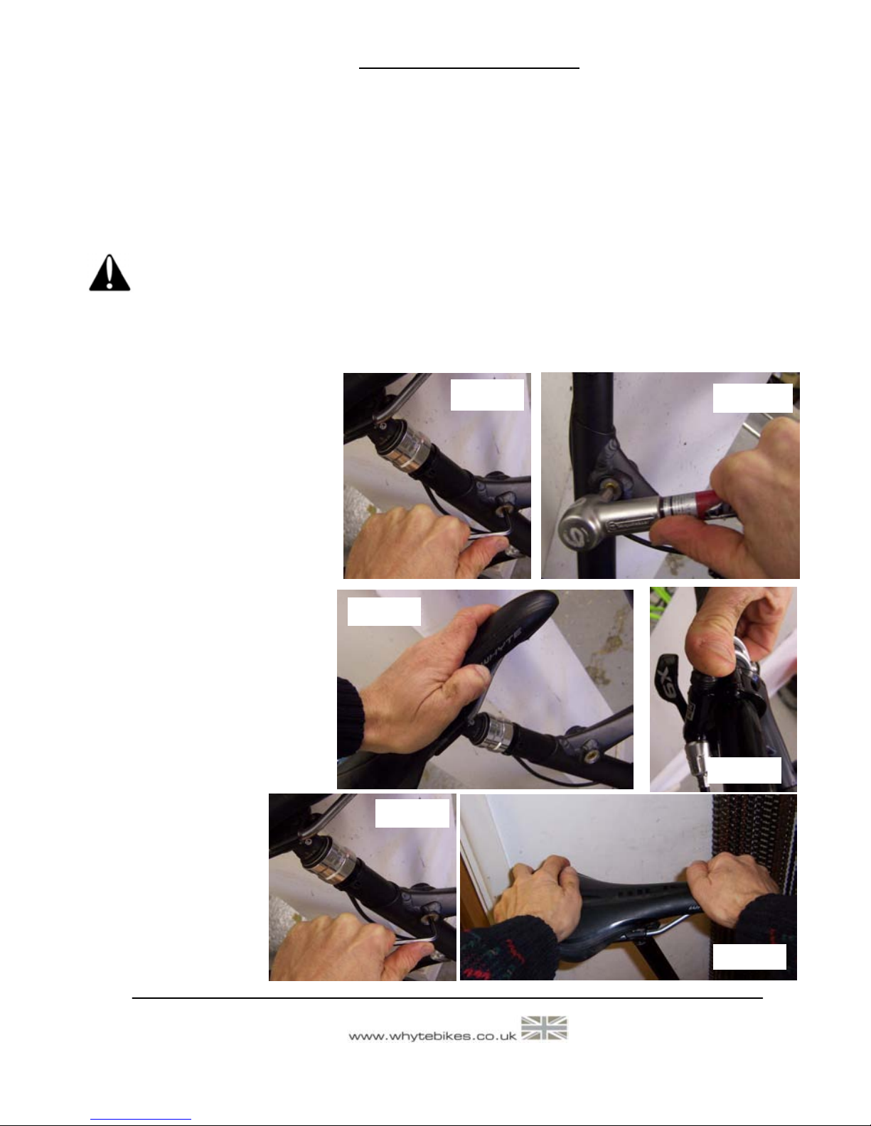
Reference figures 2 to 7. The Inter Grip seat clamp design is present on most models of
Whyte full suspension mountain bikes. It allows adjustment of the saddle height & direction.
CAUTION! Avoid over-tightening the seat clamp.
In particular, “dropper” seat-posts such as SRAM Reverb may not work correctly if the seat
clamp is over tightened.
Figure 2. To adjust the seat
height and/or direction, using
the 5mm Allen key, undo the M6
Capscrew (1) just enough to
allow the Seat Post (7) to slide
freely up and down. Set the
height and/or direction to the
desired level.
Figure 3. Re-tighten the M6
Capscrew (1) with the 5mm
Allen Key in the Torque Wrench
to the 6Nm limit, as marked on
the Plain Sleeve (2).
Figures 4 & 5. If a “dropper”
seat-post is fitted, simultaneously depress the activation
trigger and press down on the
saddle to compress the seatpost until it is fully down. Then
release the activation trigger
and the seat-post should rise
up automatically.
Figure 6. If this does
not happen, gradually
loosen the M6 Capscrew (1) with the
5mm Allen Key below
the 6Nm limit, until
the seat-post rises
automatically.
WHYTE Service Manual
Figure 2
Figure 3
Figure 4
Figure 5
Figure 6
Figure 7
Page 10
2015 Edition 1
WHYTE Service Manual
3.3: SET UP OF FORK
Tools Required: Good Quality Shock Pump.
Small Ruler
The front suspension fork fitted to your Whyte bike will be pre-set with the standard settings. Before riding, you may need to adjust these setting. First is the Sag setting on the
fork. This is to ensure the forks are set-up correctly for your own body weight, so the fork
will perform as intended.
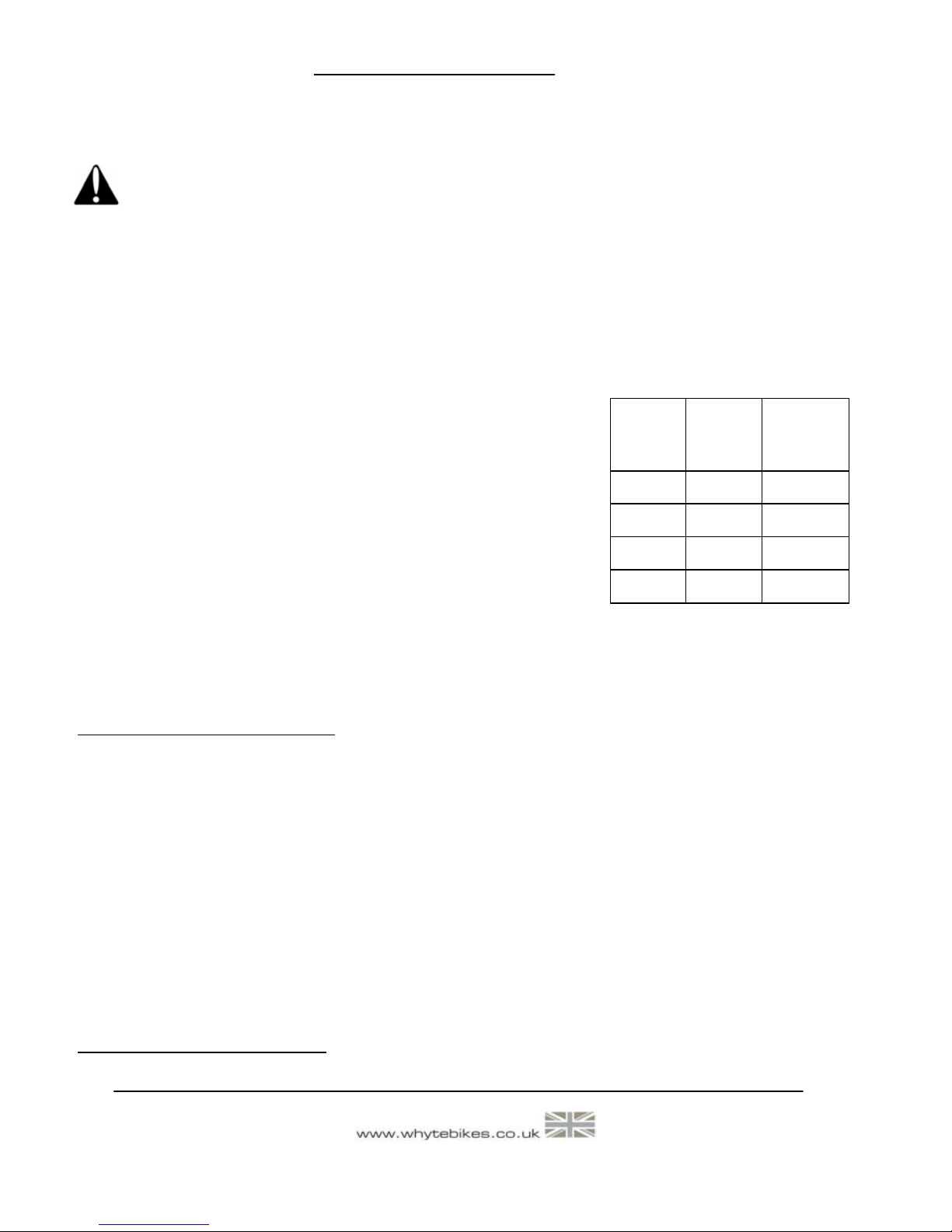
To set Sag on the front fork, you need to measure the
amount the fork compresses when you sit on the bike in the
normal riding position. See the table on the right for our
recommendation of front fork sag on your Whyte bike. To
achieve this you will need to adjust the air spring pressure
inside the fork.
Refer to the specification tables in this manual, and then to
the relevant fork manufacturers set up instructions to find
how to adjust the air spring pressure in the fork. Using a
shock pump, either add or remove air until Sag is correctly set.
Please note that for the detailed instructions for servicing and all matters relating to the
forks fitted to your Whyte bike, please refer to the manufacturers instructions.
Rebound Damping adjustment:
This adjustment fine-tunes the speed at which the wheel returns to its normal ride height
after hitting a bump. Refer to the relevant manufacturers instructions to find out how to
adjust the rebound damping. To demonstrate the effect of this function, turn the adjuster to
its slowest setting. Press down on the handlebars to compress the forks, then release the
load. The suspension recovers very slowly to its original position.
Repeat the above with the adjuster turned to the fastest setting and the difference will be
seen immediately the load is released. We recommend the optimum setting is to adjust the
re-bound damping to be as slow as possible, but not so slow that the normal ride height is
not recovered. On very rough terrain, if the bike becomes progressively lower as more
bumps are hit then the re-bound damping is set too slow. On the other hand if the bike feels
choppy and not plush then the re-bound damping is too fast. A bit of trial and error is
needed to get the exact setting.
IMPORTANT SAFETY NOTE:
Always stop riding when making adjustments of any kind to the bicycle!
Model
Sag
(15% -
Firm)
T-129 18mm
G-150 22.5mm
M109C 15mm
Sag
(25% Plush)
25mm
30mm
37.5mm
T-130 19.5mm 32.5mm
Figure 7. Then firmly twist the saddle to confirm the seat-post is still securely gripped by the
lowered torque value that allows the “dropper” seat-post to function correctly.
CAUTION! When adjusting the saddle height you MUST obey the Minimum insertion
depth requirement marked on the Seat Post (7). Also consult the seat-pin manufacturers instructions in conjunction with these notes.

Page 11 2015 Edition 1
WHYTE Service Manual
3.4: SET UP OF REAR DAMPER
Tools Required: Good Quality Shock Pump.
Small Ruler
Your Whyte bike is fitted with and air spring rear shock absorber. This means that the air
pressure in the shock absorber determines the spring rate. The correct ‘sag’ can be found
using the sliding ‘O’ ring fitted to the shaft of the shock piston. Slide the ‘O’ ring against
the shock body. Then gently sit on the bike in your normal riding position and with normal
riding gear, including back pack if applicable, and also raise your
feet off the floor. Carefully dismount and measure the distance the
‘O’ ring has moved away from the shock body.
The optimum distance for the Quad-Link rear suspension system
is shown in the table to the right. If there is less than that distance fit a shock pump and release air pressure. Conversely if
there is greater than that distance, fit the shock pump and increase air pressure.
Repeat the ‘sag’ test until the recommended sag distance is achieved.
Rear Suspension Set-up - Rebound Damping:
When the damper unit is being compressed, this is known as the compression stroke. As
the suspension unit recovers from compression back towards its full length, this is called
the re-bound stroke. All the shocks fitted as standard to the Whyte full suspension mountain bikes have factory set compression damping, and manually adjustable rebound damping.
Rebound Damping Adjustment:
The advice in section 3.3 about the fork rebound damping adjustments also applies to the
rear shock.
IMPORTANT SAFETY NOTE:
Always stop riding when making adjustments of any kind to the bicycle!
Platform Damping Adjustment.
The rear Shock fitted to your Whyte bike may have a “platform” facility to adjust the slow
speed compression damping, eg Fox “C.T.D.” (Climb / Trail / Descend) or SRAM RockShox
“Motion Control”. Please refer to the relevant shock manufactures technical information to
learn how to adjust these features.
Please note, that the Whyte rear suspension systems have been designed not to rely on
excessive low speed compression damping to obtain efficient pedalling performance, and
turning on too much low speed damping on the rear shock will compromise the suspensions sensitivity to small bump absorption and traction.
Model Sag
T-129 17mm (25%)
G-150 19mm (30%)
M109C 14mm (25%)
T-130 17mm (25%)
Page 12
2015 Edition 1
WHYTE Service Manual
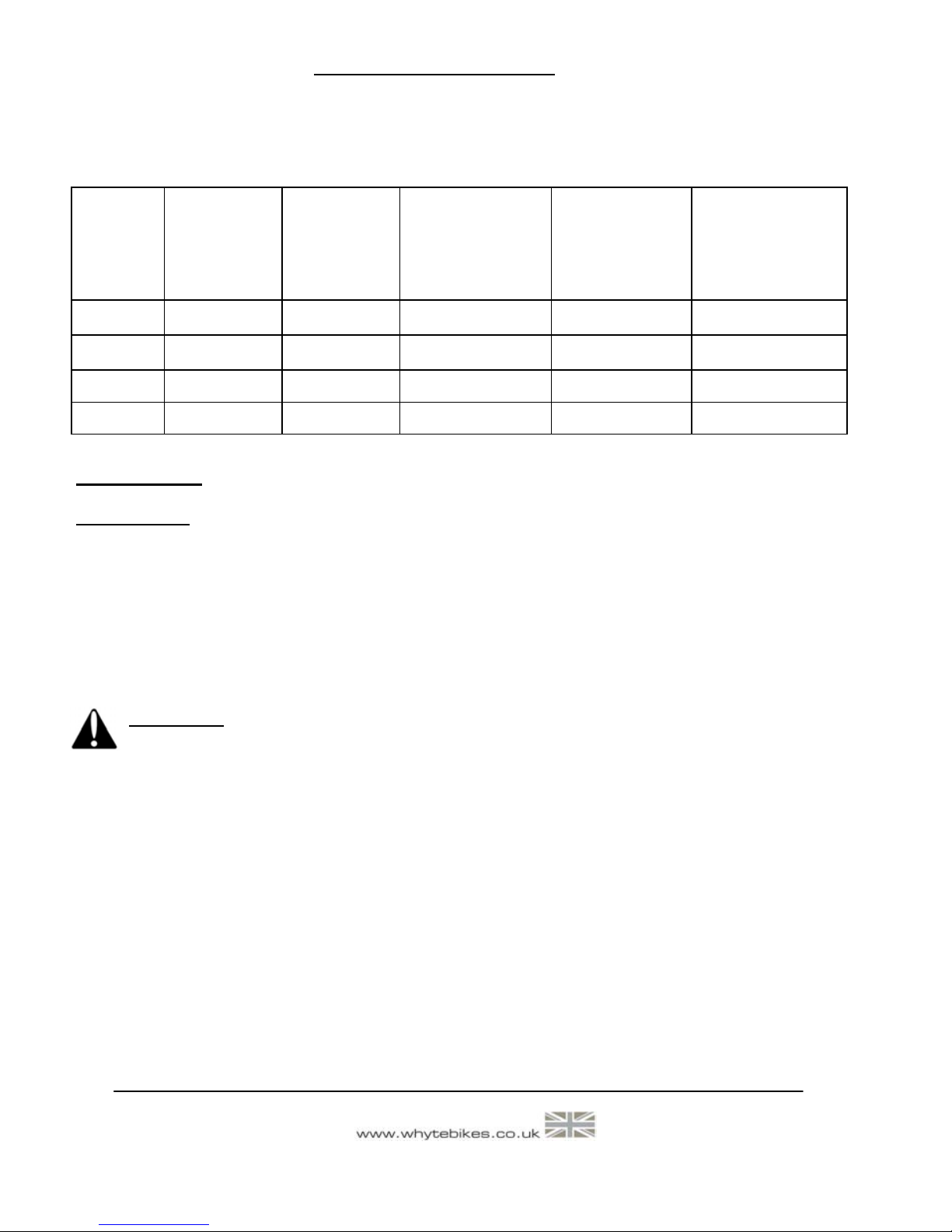
3.5: SUSPENSION TUNING LOG
Record your best suspension settings in the table below, to restore them if necessary, eg.
after dealer servicing of the suspension or if a friend has borrowed your bike.
4.0: SAFETY
IMPORTANT: The following are intended to be advisory notes on the safe use of your
Whyte bike. You should also read thoroughly the General Instruction Manual also supplied
with your new bike. If at any stage you are uncertain about the safety or safe operation of
the bike as a whole, or any specific component, then DO NOT RIDE YOUR WHYTE and
instead please consult the specific component manufacturers instruction manual or your
Whyte Dealer for advice.
Maximum Weight Limit for Whyte G-150, T-130, T-129 & M-109C:
18st. / 114kg (including rider’s luggage)
WARNING: As is the case with all mechanical components, the bicycle is subjected
to wear and high stresses. Different materials and components may react to wear
and stress fatigue in different ways. If the design life of a component has been exceeded, it may fail suddenly causing possible injury to the rider. Any form of crack,
scratches and decolouring in highly stresses areas are showing that the component
has exhausted its life time and has to be replaced. If you are in any doubt about one
or more components on your Whyte DO NOT RIDE YOUR BIKE. Consult the specific component manufacturers literature, or take your bike to your local Whyte Dealer.
Designed for the following use:
The Whyte M-109C & T-129 bicycles have all been designed, tested and comply with BS EN
14766 Safety Standard, for typical cross country, marathon enduro or trail mountain biking
use. They have not been designed or tested for extreme down-hilling or free-riding.
The Whyte G-150 & G130 bicycles have all been designed, tested and comply with BS EN
14766 Safety Standard, for typical free-ride or gravity enduro mountain biking use. It has
not been designed or tested for extreme down-hilling.
Date
Rider Weight
(including all
riding kit)
(kg or lbs)
Fork Pressure
(bar or P.S.I)
Fork Rebound
Damping
(# of clicks from
softest setting)
Shock Pressure
(bar or P.S.I)
Shock Rebound
Damping
(# of clicks from
softest setting)
Page 13 2015 Edition 1
WHYTE Service Manual
5.0: LUBRICATION
Please refer to the Whyte General Instruction Manual for guidance about lubricating many
of the components on your Whyte bicycle.
For the range of bicycles contained in this Supplementary Service Manual, there is also the
following specific guidance:
5.1: WHYTE INTER GRIP SEAT CLAMP
5.2: GENERAL WHYTE LUBRICATION
For the correct lubrication regime and maintenance of all parts on a Whyte bicycle, please
refer to the specific component manufacturers detailed instructions bundled with this manual or for further information visit the specific manufacturers website.
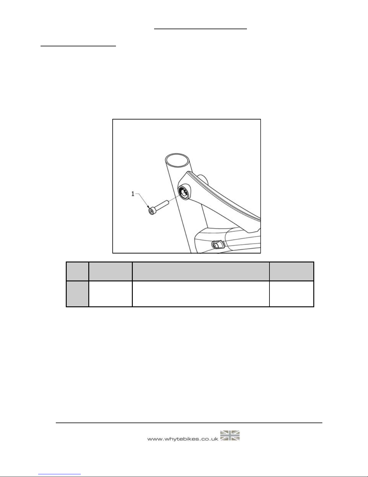
Figure 8: Capscrew Lubrication
Item Lubricant
Lubrication
Interval
1
SKF LGEP2 or Castrol Spheerol AP3 or Finish
Line Teflon White Lithium Complex grease
Once a Month
Description
M6 x 30mm
Capscrew

Page 14
2015 Edition 1
WHYTE Service Manual
6.0: SERVICING THE REAR SUSPENSION
6.1.1: Remove the Rear Shock, Links & Swinging Arm from the Whyte G-150
Tools Required: 4mm AF Allen Keys (2 off)
5mm AF Allen Key - ball ended (1 off)
6mm AF Allen Key (1 off)
8mm AF Allen Key (1 off)
15mm Open-ended, or adjustable spanner
T-25 Torx® Keys (2 off)
10mm AF Socket (2 off)
6.1.1.1 To remove only the rear shock absorber (6) from the frameset.
Whilst referencing figure 9, using the T-25 Torx®) Keys, undo the two M5 x 16mm long Sockethead Capscrews (1) from the Ø8mm x 31mm long Hollow Pivot Pin (3) that passes through the
Main Frame (16) and front of the Rear Shock Absorber (6). Whichever Capscrew (1) becomes undone first, remove it and the adjacent Collar (2), and pull the Pivot Pin (3) all the way out from the
other side.
Using the 6mm AF Allen Key and the 8mm AF Allen Key, undo and remove both the Flanged Nut
M12 x 19mm long (4) from the Flanged Screw M12 x 15mm long (5), that pass through the Shock
Extender (7) and the rear of the Rear Shock Absorber (6). You can now remove the Rear Shock
Absorber (6).
6.1.1.2 To remove the H-link (20) & swinging arm parts (17, 18 & 19) from the main
frame (16).
Again, whilst referencing figure 9, using the 15mm open ended spanner, unscrew and remove the
two M22 Bearing Caps (7) at the front of the H-link (20). Next, using the 10mm AF sockets, undo
the M8 Aerospace nuts (9) on the M8 x 71mm long stud (10) that passes through the H-link (20)
and Main Frame (16). Whichever Aerospace Nut (9) becomes undone first, remove it, and then
remove the M8 x 71mm long stud (10) from the other side.
Next, using the T-25 Torx®) Key, unscrew and remove the two M8 x 23 long Flanged Screws (14)
from either side of the Chainstays (19). The Seat-stays (17 & 18) together with the H-link (20)
may now be removed from the Main Frame (16) & Chainstays (19). Be careful to retain all the
shield washers (Items 2, Figure 13 & Items 2 & 3, Figure 15) ready for re-assembly.
Then, using the two 4mm AF Allen keys, undo the two M6 x 20mm long countersunk-head cap
screws (11) in the M6 x 70mm long hollow pivot pin (13). Whichever countersunk head cap screw
(11) becomes undone first, remove it and the adjacent collar (12), and then remove the M6 x
70mm long hollow pivot pin (13) from the other side. The Chainstays (19) may now be removed
from the Main Frame (16). Be careful to retain all the shield washers (Items 2, Fig 13) ready for re
-assembly.
To separate the Seat-stays (17 & 18) from the H-link (20), whilst referencing figure 10, using the
15mm open ended spanner, unscrew and remove the four M22 Bearing Caps (8) at the rear of the
H-link (20). Next, using a 10mm Socket and the 5mm AF Allen Key, undo the M8 Aerospace nuts
(9) on the M8 x 20 long Socket-head Capscrews (15) that passes through the H-link (20) and seatstays (17 & 18). The Seat-stays (17 & 18) may now be removed from the H-link (20). Be careful
to retain all the shield washers (Items 2, Fig 10) ready for re-assembly.
 Loading...