


n
Strictly Confidential 1 of 26
User Manual
For the model for WMPI-01
Prepared By: Joel Giles Cheang
Dated:
Approved By:
_______________________
Pankaj Sharma
CTO
Whizpace Pte. Ltd.
Singapore
Date:
COPYRIGHT NOTICE
Copyright by Whizpace Pte. Ltd., Singapore. All rights reserved. No part of this publication may be
reproduced, transmitted, transcribed, stored in a retrieval system, or translated into any language
without the written permission of Whizpace.

n
Strictly Confidential 2 of 26
Role
Name
Designation
Signature
Owner
Reviewer
Approver
Version
WARNING
Check document control system for the latest version before using or copying.
REVISION HISTORY
Version
Date
Authors
Comments
Reasons for
Change
0.1

n
Strictly Confidential 3 of 26
CONTRIBUTORS
- Benjamin Lim Zheng Jie
- Boonyang Tan
- Chiu Ying Lay
- Hong Feng
- Joel Giles Cheang
- Oh Ser Wah
- Pankaj Sharma
- Alger Goh
- Swe Zin

n
Strictly Confidential 4 of 26
DEFINITIONS, ACRONYMS & ABBREVIATIONS
AC
Alternating Current
BPSK
Binary Phase-Shift Keying
CPU
Central Processing Unit
dB
Decibel
F/B Ratio
Front-to-Back Ratio
FCC
Federal Communications Commission
GUI
Graphics User Interface
IMDA
Info-Communications Media Development
Authority
IP Address
Internet Protocol Address
KM
Kilometre (Unit of Measurement)
Mbps
Megabits per second
MHz
Megahertz
No.
Number
OFDM
Orthogonal Frequency-Division Multiplexing
PoE
Power over Ethernet
QAM
Quadrature Amplitude Modulation
QPSK
Quadrature Phase-Shift Keying
RF
Radio Frequency
RX Rate
Receiving Rate
SDRAM
Synchronous Dynamic Random Access
Memory
SMA Antenna
SubMiniature A Antenna
SSID
Service Set Identification
TCP
Transmission Control Protocol
TVWS
Television White Spaces
TX Rate
Transmitting Rate
UDP
User Datagram Protocol
WEP
Wired Equivalent Privacy
WPA
Wi-Fi Protected Access
WPA2
Wi-Fi Protected Access 2

n
Strictly Confidential 5 of 26
FCC Regulatory Information
This device complies with part 15 of the FCC Rules. Operation is subject to the following two
conditions: (1) This device may not cause harmful interference, and (2) this device must accept any
interference received, including interference that may cause undesired operation.
Any changes or modifications not expressly approved by the party responsible for compliance could
void the user’s authority to operate the equipment.
Part 15 TV Band Device Notice
This equipment has been tested and found to comply with the rules for TV bands devices, pursuant
to part 15 of the FCC rules. These rules are designed to provide reasonable protection against
harmful interference. This equipment generates, uses and can radiate radio frequency energy and,
if not installed and used in accordance with the instructions, may cause harmful interference to radio
communications. If this equipment does cause harmful interference to radio or television reception,
which can be determined by turning the equipment off and on, the user is encouraged to try to
correct the interference by one or more of the following measures:
(1) Reorient or relocate the receiving antenna.
(2) Increase the separation between the equipment and receiver.
(3) Connect the equipment into an outlet on a circuit different from that to which the receiver is
connected.
(4) Consult the manufacturer, dealer or an experienced radio/TV technician for help.
Caution: Exposure to Radio Frequency Radiation.
To comply with FCC RF exposure compliance requirements, for fixed configurations, a separation
distance of at least 40 cm must be maintained between the antenna of this device and all persons.
This device must not be co-located or operating in conjunction with any other antenna or transmitter.
HQ Contact:
Whizpace Pte. Ltd.
77 Ayer Rajah Crescent,
#02-30,
Singapore-139954
US Contact:
Virtual Gateway Labs.
1732 North First Street, Suite 220,
San Jose, California 95112
USA
Phone: +1 408 453 4557
Fax: +1 408 453 4046
Website: http://www.vg-labs.com/

n
Strictly Confidential 6 of 26
Table of Contents
COPYRIGHT NOTICE ...................................................................................................................................................... 1
WARNING ......................................................................................................................................................................... 2
REVISION HISTORY ........................................................................................................................................................ 2
CONTRIBUTORS ............................................................................................................................................................. 3
DEFINITIONS, ACRONYMS & ABBREVIATIONS ........................................................................................................... 4
1. INTRODUCTION ...................................................................................................................................................... 7
1.1. PURPOSE ............................................................................................................................................................................. 7
1.2. PRODUCT OVERVIEW ............................................................................................................................................................. 7
2. SYSTEM BLOCK DIAGRAM .................................................................................................................................... 7
3. HARDWARE SETUP AND CONFIGURATION........................................................................................................ 8
3.1. SETUP (TP-LINK POE) ........................................................................................................................................................... 8
3.2. SETUP (TP-LINK SWITCH) ....................................................................................................................................................... 9
3.3. LED INDICATORS ON WHIZMESH .......................................................................................................................................... 10
4. GUI CONTROL INTERFACE ................................................................................................................................. 11
5. SPECIFICATIONS .................................................................................................................................................. 20
5.1. WHIZMESH KEY FEATURES ................................................................................................................................................... 20
5.2. WHIZMESH HARDWARE SPECIFICATIONS ................................................................................................................................ 21
5.3. INTERNAL ANTENNA SPECIFICATIONS ...................................................................................................................................... 21
6. MODES OF OPERATION ...................................................................................................................................... 25
6.1. POINT TO POINT OPERATION ................................................................................................................................................. 25
6.2. OPERATION IN STAR TOPOLOGY ............................................................................................................................................. 25
6.3. WHIZMESH NODES FORMING A MESH TOPOLOGY ................................................................................................................... 26
n
Strictly Confidential 7 of 26
1. Introduction
1.1. Purpose
The purpose of the manual is to provide a quick guide with appropriate information and procedures
on how to setup and operate the WhizMesh radio to establish a TV White Space (TVWS) radio link.
1.2. Product Overview
WhizMesh is a wireless communication solution based on dynamic sharing technology that make
use of the underutilized TV Band, also known as TVWS. WhizMesh are designed to provide long
range and good penetration characteristic which can lower down the cost of network and increase
the speed of deployment. It supports mesh topology on top of the traditional point-to-point and point-
to-multi-point (star) topologies.
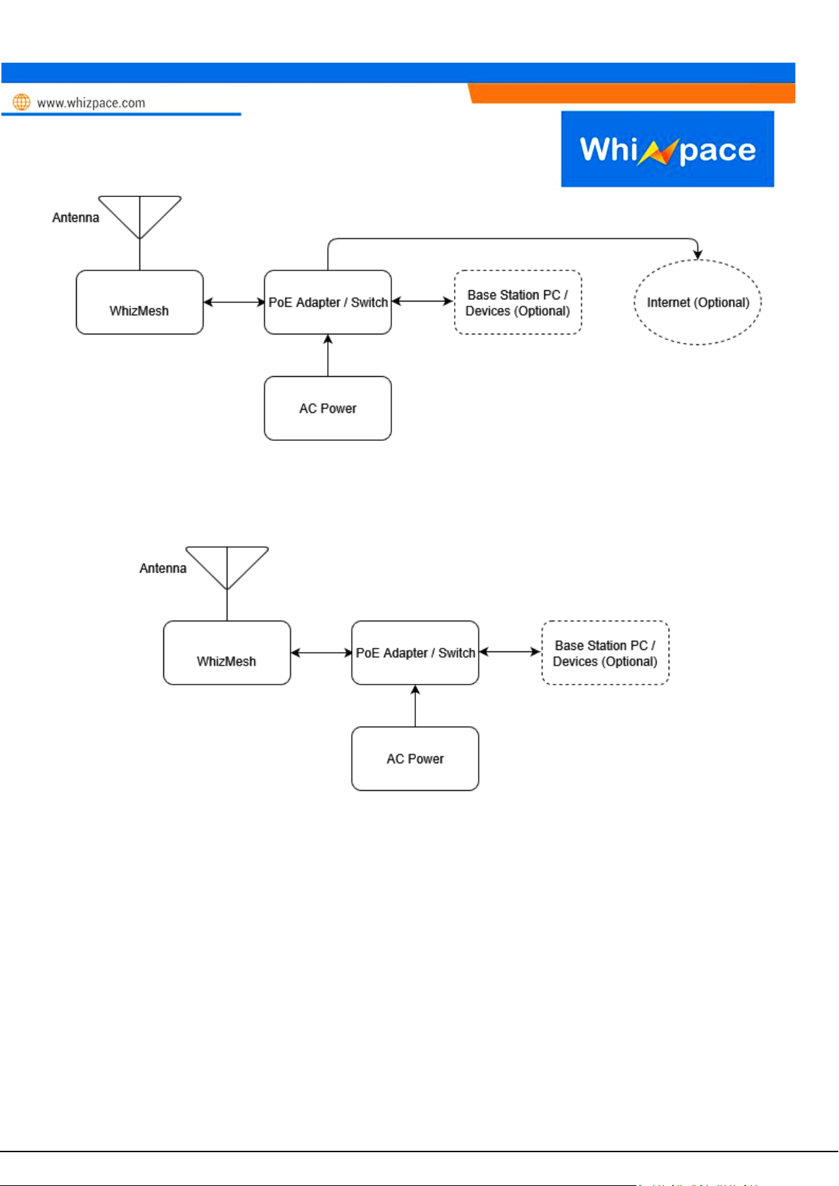
2. System Block Diagram
This part will show the basic block diagram of WhizMesh installation for different applications.
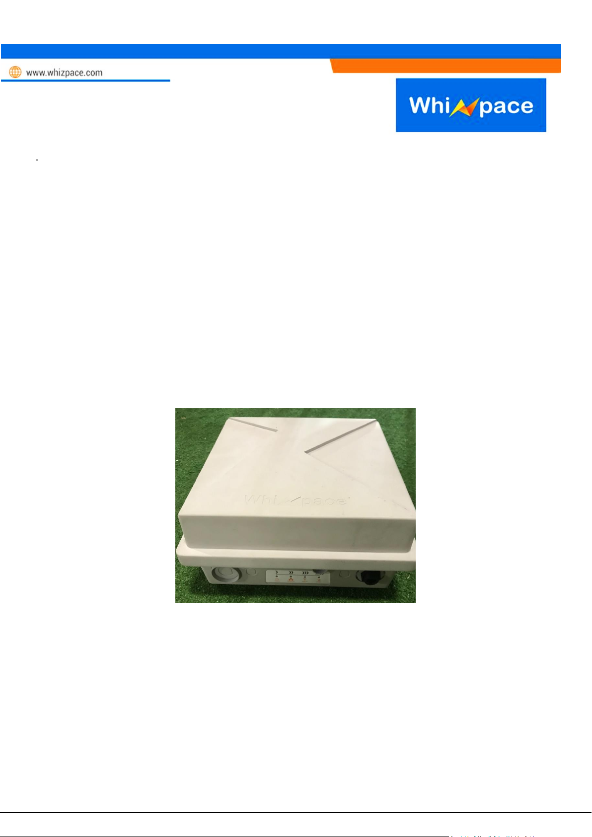
Figure 1: Whizmesh
n
Strictly Confidential 8 of 26
Figure 2: Base station installation diagram.
Figure 3: Client station installation diagram.
The TVWS radio link is established between both the base station and client station for different
applications
3. Hardware setup and configuration
3.1. Setup (TP-Link PoE)

n
Strictly Confidential 9 of 26
1. Connect AC power cord to PoE Adapter
2. PoE Ethernet OUT to WhizMesh
3. PoE Ethernet IN to Base Station PC
Figure 4: Connection between Whizpace device with laptop Figure 5: Connection of POE
3.2. Setup (TP-Link Switch)
1. Connect AC power cord to TP-Link Switch
2. TP-Link Ethernet ports 1 - 4 to WhizMesh
3. TP-Link Ethernet port 5 – 8 to Base Station PC
Figure 6: Connection between Whizpace products and laptop using TP-Link Switch

n
Strictly Confidential 10 of 26
3.3. LED Indicators on WhizMesh
Figure 7: LED Indicators on Whizpace Products
4. POWER – Display the ON/OFF Status of WhizMesh
5. ETHERNET – Display if the Ethernet Port is active and functioning
6. SINGNAL – Not applicable
7. DIAG. – Not applicable

n
Strictly Confidential 11 of 26
4. GUI control interface
All General Status of the WhizMesh is displayed on
the first page of the GUI
Eth0:
ESSID: Network Name
Mode: Base Station/Client Station
Channel: Current Network Channel
TX Power: Transmission Power in dBm
Link Quality: Quality of the connection between the
two devices
Signal Level: Strength of connection in dBm
Noise Level: Channel Noise Level in dBm
*For simple link setup, users could use the default
values and skip the other pages of the GUI
Figure 8: General Status of the products

n
Strictly Confidential 12 of 26
Enabling the bridge let users wirelessly connect two interfaces together.
Figure 9: Enabling Bridge Interfaces in Network Configuration

n
Strictly Confidential 13 of 26
Figure 10: Disabling the Bridge Interfaces in Network Configuration

n
Strictly Confidential 14 of 26
Figure 11: Enable Wireless Configuration
• Select your suitable ESSID, Operating Channel, Mode and TX power

n
Strictly Confidential 15 of 26
• Select your routing.
• (Optional) Use options Add Route & Edit Default Gateway if you require customized routing.
Figure 12: Routing

n
Strictly Confidential 16 of 26
• Run tests to find out your ping and bandwidth details
• Display the routing table
• Reboot the device
Figure 13: Diagnostic Testing of the products

n
Strictly Confidential 17 of 26
• Run command Lines on the GUI
Check with Whizpace for supported command lines
Figure 14: Running command lines through the web interface

n
Strictly Confidential 18 of 26
• Save the current configuration
• Reset the WhizMesh device
Figure 15: System Configuration

n
Strictly Confidential 19 of 26
Figure 16: Changing password for the GUI

n
Strictly Confidential 20 of 26
5. Specifications
5.1. WhizMesh Key Features
• No need line-of-sight communication
• Long range communication up to 10 km (line-of-sight)
• Data rates from 1.5 to 16.25Mbps
• Supports point-to-point, point-to-multipoint and mesh topologies
• Supports up to 2,000 connection associations
• Supports various networking protocols such as TCP/IP & UDP
• Supports traffic prioritization queues for video, voice and data applications
• Secured communication with WEP, WPA or WPA2 security
• Built-in antenna
• Supports 24V/48V Power-over-Ethernet for ease of deployment
• Operation in license-exempt TV White Space bands
• P65 ratings for outdoor deployment

n
Strictly Confidential 21 of 26
5.2. WhizMesh Hardware Specifications
System Specifications
Product
WMP-ID6-01
Mesh Topology
Occupied Channel
Bandwidth
5MHz
Channel Spacing
6/8MHz (configurable to 5,6 or 7 MHz)
Data Rates (For a
Single Channel)
16.25, 13.5, 12, 9, 6, 5.5, 4.5, 3, 2.5, 2.25, 1.5, 1.25, 0.25 Mbps
Step size
1MHz
Modulation
OFDM, QAM, QPSK, BPSK
Range
Up to 5 km
Number of Nodes
Up to 2,000 associations
Transmit Power
Up to +17dBm (Operational) exclude Antenna
Receiver Sensitivity
-96dBm @ 1.5Mbps (Typical)
Maximum System
Gain
113dB (Without Antenna)
Back End Interface
IP
Processor
Atheros CPU 533MHz
Flash
8MB Strata Flash
SDRAM
32MB SDRAM
RF Port
N/A
Antenna
Internal 6 dBi 78º Beamwidth
Mechanical Specifications
Dimension
25x25x18 cm
Weight
Enclosure
Plastic Casing IP65
Mounting
Pole Mount
Environment Specifications
Operating
Temperature
-30 to +70ºC
Operating Humidity
Up to 95% non-condensing
5.3. Internal Antenna Specifications
Antenna Specifications
Frequency Range
450 – 750 MHz
Gain
5.0 dBi
F/B Ratio
>=15dB
3-dB Beamwidth
~78° (xz-plane)/~66° (yz-plane)
VSWR
<=1.4
Polarization
Vertical
Maximum Power
10W

n
Strictly Confidential 22 of 26
Impedance
50Ω
Connector
MMCX (male)
Mechanical Specifications
Weight
250 gm
Dimensions
23cm x 15cm x 7cm
Antenna Color
White
Figure 20: 3-D Simulated radiation patterns

n
Strictly Confidential 23 of 26
Figure 21: Return Loss with Frequency
Figure 22: 3D Gain with Plot

n
Strictly Confidential 24 of 26
Sl N0.
FREQUENCY
(MHz)
GAIN (dBi)
1
400
6.4 2 450
5.4 3 500
4.0 4 550
7.5 5 650
8.2 6 750
6.1
Figure 23: Gain Measurement with frequency
Figure 24: Radiation pattern Horizontal BW
Figure 25: Radiation pattern Vertical BW

n
Strictly Confidential 25 of 26
6. Modes of Operation
6.1. Point to point operation
Figure 26: Point-to-point operation
6.2. Operation in Star Topology
Figure 27: Whizpace product operation in Star Topology

n
Strictly Confidential 26 of 26
6.3. WhizMesh Nodes forming a MESH topology
Figure 28: Whizpace product operation in MESH Topology
 Loading...