


Installation and Operations Manual
WhiteWing Dehumidifiers
SuperDry 90
DEHUMIDIFIERS
P:+888-236-7231
Add: 300 E Valley Drive, Bristol, VA 24201

DEHUMIDIFIERS
※ ※Safety Notes
The WhiteWing Series Dehumidifier must always be connected using a grounded
electrical connection as required for all electrical appliances. The warranty is voided and all
responsibility for the operation transfers to the owner if non-grounded wiring is
utilized.
WhiteWing
Before moving the dehumidifier, turn off dehumidifier and allow pump to empty
reservoir. (Or if unit is already off, press“P”button to confirm drain reservoir is empty).
After the pump has finished operation, unplug the power cord and relocate unit to the
desired position.
If the inside of the unit has gotten wet for any reason, the unit should be opened
and allowed to dry thoroughly before reconnecting to electric and restarting.
For proper operation, neither the inlet nor discharge should be positioned against a
wall. A minimum of 12”clearance between unit and any obstruction is required.
Do not insert any objects or fingers into the inlet or discharge.
All work on unit should be done with the unit“off”and unplugged.
Do not use water to clean unit exterior. Only use a damp cloth to clean exterior and
always unplug the unit first.
Do not use unit as shelf or device to hang clothes. This could cause damage to unit.
Do not stand on machine.
WhiteWing Dehumidifiers must be maintained and serviced by qualified technicians.
Dehumidifiers are intended for use only when the unit is installed in a level
and upright position. Operating the unit in any other position could cause water to come
in contact with the electrical components.

DEHUMIDIFIERS
DEHUMIDIFIERS
※ ※Features/Specifications
The SuperDry Series dehumidifier operates based on the refrigerant principle of
dehumidification.
Automatic (Humidistat) or Manual Control
If power is interrupted during operation, the unit will automatically
restart when power is restored.
Eco-Friendly R410A Refrigerant
Easy access for routine maintenance
Unit can be ducted, if necessary
Pump safety feature – overflow protection
High COP, 2.45L/KWh
Low Sound Levels <56dBA
Self-monitoring system
Drain Pump with both Automatic and Manual Control
Each unit comes standard with a prefilter and Merv 8 filter. High efficiency
and carbon filters are available as options.
SuperDry 90
Identification:
-1-
Contact your installing contractor
Phone
SuperDry Dehumidifiers: +888-236-7231
Customer Service:
For additional questions concerning the operation of your dehumidifier,
For future reference, write down the model, serial number, and date of purchase so
you can identify your unit when seeking assistance. NOTE: data label on back of unit
includes serial number.
Model Number SuperDry 90
Serial Number__________________________
Date of Purchase__________________________
please:
※ ※Table of Contents
Features/Specs.............................................................................................................................. 01
Identification................................................................................................................................. 01
How Your SuperDry Dehumidifier Works..............................................................................02
Unit Overview................................................................................................................................ 03
Operating instructions................................................................................................................ 04
Preparing the Unit for Use.......................................................................................................... 10
Maintenance.................................................................................................................................. 12
Storing Your Dehumidifier.......................................................................................................... 16
Troubleshooting........................................................................................................................... 16
Warranty......................................................................................................................................... 17
Congratulations on purchasing a WhiteWing Dehumidifier! Your new dehumidifier
comes with an extensive warranty plan.
DEHUMIDIFIERS
DEHUMIDIFIERS
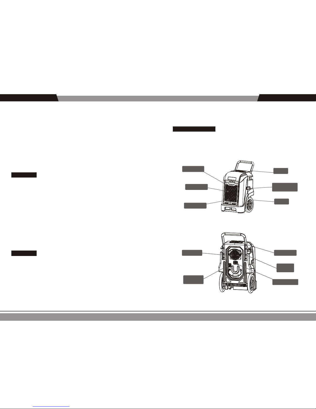
SuperDry 90
※ Front View
Handle
Wheel
Front cover
Air inlet
Secured Access
Latch
Air Filter
-3-
※Unit Overview※
Control panel
Power Cord Input
Hose and
Cord Rack
Drain Tube
Connection
Air outlet
※ Rear View
-2-
How Your SuperDry Dehumidifier Works
The WhiteWing SuperDry Series Dehumidifier utilizes either its integral humidistat to
monitor the conditioned space or a manual on/off control to energize the compressor
when needed. Air is drawn across an evaporator coil. The evaporator coil is cooler than the
dew point of the air so water vapor will turn into liquid condensation. Air is then reheated
through the condenser coil and distributed back into the room.
Installation:
240 Volts AC may cause serious injury from electric shock.
WARNING!
1. Disconnect electrical power before servicing
2. Only plug unit into grounded electrical outlet
3. Do not use extension cord
4. Do not use plug adapter
Power Supply: 115V, 60 Hz AC Only 1 Phase
Outlet Requirement: 3-Prong, GFI
Circuit Protector: 15 Amp Time Delay Fuse or Circuit Breaker
Alternatively, you can manually control unit to operate independent of space conditions.
Place unit in desired location. The inlet of unit should be at least 8”from any
obstructions. If unit is transported in the horizontal position, allow it to sit in upright
position for at least 30 minutes before operating.
It is recommended that the unit be removed from any location where corrosive or high
VOC content materials are applied.
WARNING!

DEHUMIDIFIERS
DEHUMIDIFIERS
-5-
6. LCD monitor
When the unit is running, the LCD monitor will go dark if no buttons are pushed. Push
any button once to light monitor.
7. LCD display function
(1)Show“Power On”when the machine has already connected but not started.
p
o w e
r
o
n
Use to confirm a selection.
4. Select/OK Button
OK
These buttons are used for adjusting humidity or timer settings.
5. UP Botton Down Botton
Humidity Setting: Adjust the humidity setpoint
Timer Setting: Start Time Setup/Stop Time Setup/Cycle Time Setup
Temperature Scale Switch: Choose between Celsius and Fahrenheit readings
Return: Return to the main menu
NOTE: See Section 8 for more detailed programming instructions.
Four selections are available:
n
U
n
i
t
O
(2) Show“Unit On”when the machine is in working status (This display will change
to next screen in 2 seconds).
(3)The LCD interface shows two lines of data. The first line displays the room
temperature and humidity. On the second line, Job T(working time) and Humidity Setpoint
are displayed on an alternating basis.
I
n
l
e
t
3
2
℃
7 6
%
The contents of the second line alternate every 10 sec.
※Operating instructions※
OK
M
P
Menu
Up Button
Down Button
LCD Monitor
On/Off
Select/OK
Drain Pump
※ Control Panel Operation
1. ON/Off Button
Press this button, and the machine will start running. Press this key again and the
machine will stop running. The display will show room humidity levels except while you’re
pressing another button. NOTE: When unit is turned off, the fan will run for 1 minute prior
to shutting off. “ In addition the condensate pump will pump for approximately 14
seconds to drain the pump reservoir after unit is powered off.”
2. Pump Button
P
For extende d storage or m ovement of the machi ne, press the“Pump”bottom to
remove water from the integral pump’s reservoir.
3. Menu Button
M
Pressing the Menu (M) button, gives you the options to select between two different
control modes as well as adjust the temperature measurement units. Continue pressing
the M button until you get to your desired selection. Press the Select (OK) key to confirm
that selection and move to a submenu.
After you’ve completed your task, select“R”,then press the“select/ok”button to
move back to previous menu, or wait 10 sec to automatically return to the main screen.
-4-

DEHUMIDIFIERS
DEHUMIDIFIERS
T
i
m
e
O
n
0 0 0
5
T
i
m
e
O 0 0 0
5
f f
O
000 000
I
1 1
H
u
m
i
d
T
i
m
e
r
T
e
m
p
U
R
Time remaining to Auto opening
Time remaining to Auto Closing
Time remaining to circulate status
( 1 ) The Humidity Setting (Humid)
a. Press the Menu (M) button. The screen shows:
b. Press the“M”button until “Humid”is flashing. Press “OK”to select this option. The
screen shows:
8. Operation and Display
Note: As long as the machine is plugged into power, the settings can be changed. The unit does
not have to be operating to change setup.
Second screen display options:
J
o
b
.
T
0 0 0
5
0 8 9
L
f
e
i
.
0
H
or
-7-
H
u
m
i
d
R
S
e
t t
i
n
g
3
5
%
c. Press the menu key until the humidity level (bottom left of display) is flashing (it will
either say“Co”f or continuous operation or a number for a specific percentage).
d. Use the“Up”or“Down”buttons to set the machine to your desired level. Press the
“OK”button when finished. The cursor automatically move to“R”which will be flashing.
Press“OK”to confirm move to previous menu or wait 10 seconds and you will
automatically return to the main menu.
-6-
The contents of the second line alternate every 10 sec.
or
J
o
b
.
T 0 0 0
5
H
u
m
i
.
s e
t
5
0
%
(5)
.
Show“Draining”when the pump is draining in both automatic and manual
modes
I
n
l
e
t
3
2
℃
7 6
%
D
r
a
ini
n
g
Once the pump reservoir is drained, the contents of the second line alternately show “job hours”
and “total hours”, alternating every 10 seconds until the one minute final fan cycle is completed.
J
o
b
.
T
0 0 0
5
0 8 9L
f
e
i
.
0H
or
(4)When you press the“Power Off”button, two lines of data will be displayed. The
top line will read“Unit Off”. The bottom line will read“Draining”for approximately 14
seconds while the pump is emptied.
f f
U
n
i
t
O
D
r
a
ini
n
g
Show“Defrosting”when the machine is in defrosting mode. If both“Defrosting”and
“Draining”are occurring simultaneously,“Defrosting”is the display priority.
I
n
l
e
t
3
2
℃
7 6
%
D
i
g
f
t
e
n
r
o s
(6) .Second line of display will rotate through several screens depending on setup
f f
U
n
i
t
O

DEHUMIDIFIERS
DEHUMIDIFIERS
-9-
a. Press the M button until the T.I/O selection is flashing. Press“OK”button to select.
b. Use the“Up”and“Down”arrows to adjust the hours and minute of the first cycle.
c. Use the“M”button to move from 1st line of display to second and adjust second
time period with up and down buttons.
d. Press the“OK”button to confirm the time. (Flashing OFF will turn to ON).
( 3 ) Temperature scale set
This selection allows you to switch the machine from displaying temperature in
degrees Celsius to degrees Fahrenheit.
a. Press the menu key. The screen shows: Humid, Timer, Tempu, R.
H
u
m
i
d
T i
mer
T
e
m
p
U
R
T
e
m
p
U
R
S
e
t t
i
n
n
g
O O
ff
o
F
℃
b. Press the Menu key unit TempU flashes. Press“OK”to select.
c. The screen shows: Celsius degree℃ on/off and Fahrenheit degree the ℉ off/on.
a. Press the M button until the T.off button is flashing. Press“OK”to confirm.
b. Set timer as above.
2) Shut Off Time (T.offSelection). Unit will run for designated time and then turn off.
3) Cycling Timer (T.I/O Selection)
The third selection, T.I/O, lets you set up the machine to cycle on and off during a
specific time frame. For example, you could set the unit to run 8 hours a day and remain
off the other 16 hours. Note: You are selecting on and off periods of time, not set clock
times.
d. Press the menu key to move the cursor to the ℃ on/offor ℉ off/on(flashes).
e. Press to confirm key. The on/off status of C and F will exchange.
-8-
( 2 ) Timer Settings (Timer)
This selection allows you to set a timer for the unit to turn on or turn off. You can also set up cycle
timing, which allows you to set up and repeating cycle of specific on and off durations.
a. Press the menu key several times unit the Timer button is flashing.
Press“OK”button to confirm this option.
f f
n
oo
T
T
T
R
/
.
..
I
0
b. The screen shows: T. on, T. off, T.I / 0,R
H
u
m
i
d
T
i
m
e
r
T
e
m
p
U
R
“
“T.off” – Unit will stop when timer expires
“T.I/O” – Unit will cycle“on”and“off”based on the set time. If unit is off, the
cycling will start with unit“off”. If unit is on, the cycling will start with the unit“on.”
c. Press the menu key to select your desired selection.
T.on” – Unit will start when timer expires
T
i
m
e
r
O
n
O
R
f f
00 00
1) Start Time (T.on Selection)
a. Press to confirm key. The screen runs as follow, the first 00 positions (flashes) at the
same time.
b. Press“Up”and“Down”key to select hour choice between 00-24. Press“Ok”key
to select choice.
c. After the hour selection is confirmed, the minute choice will flash. Select as before
and confirm with“Ok”key.
d. The“OFF”button will now flash. Press“OK”one more time, the“OFF”display will
switch to“ON”and the timer is now set.

DEHUMIDIFIERS
DEHUMIDIFIERS
-11-
The quick connector into
the socket on the connector
Quick connection to draining tube
(
( 4 ) Set unit control as desired and energize.
3 ) Firmly insert power cord into socket on top back of unit.
SuperDry 90
※Maintenance and Repair※
1. Exterior Cleaning
Use a soft, slightly damp cloth to wipe the plastic body.
a. Remove the inlet grille to access the filter
2. Filter cleaning
18’prior to reaching final drain location.
-10-
Ducting of the unit allows conditioning of an adjacent room or focusing discharge in
an area needing focused attention. Diameter for supply ducting is 6”. Flex or layflat
ducting can be used for this purpose.
9.Optional Duct Installation
SuperDry 90
※Preparing the Unit for Use※
( 1 ) Position the machine for a minimum 8”clearance on front and sides. Rear of
machine should be positioned for maximum discharge distance or directly towards a
specific location for spot drying.
If the unit was moved in such a manner that the compressor didn’
t remain in a
vertical
orientation, wait a minimum of 30 minutes before turning the unit“on.”
( 2 ) The included drain line attaches to the unit via a quick connection type fitting
located on the base of the unit.The drain line should be routed to a suitable drain or
outside. Because the unit features an integral drain pump, drain line may go vertically up

DEHUMIDIFIERS
DEHUMIDIFIERS
-13-
b. Pull up the bottom to open
Press this button and pull to open
c. Opening back housing
Hand in this
slot to open
Release this screw at both side,
and open these box locks
-12-
1) Pull up on the handle to
release and gently pull out
on filter assembly.
2) Remove the filter
SuperDry 90
b. Filter may be cleaned by vacuuming or by washing with warm water (no soap or solvents).
Insure filter is dry prior to restarting unit.
※Maintenance
1. Accessing Internal Components
WARNING – ALWAYS UNPLUG UNIT PRIOR TO PERFORMING ANY
MAITENANCE
a. Remove tamperproof screws from side latches

DEHUMIDIFIERS
DEHUMIDIFIERS
-15-
※ At least once per year, clean pump system
Basic-
1. Press the pump button (P) to drain water from reservoir.
2. Disconnect power to dehumidifier.
3. Mix a 16 oz solution of either 1 oz bleach to 15 oz water or 4 oz white vinegar to 12
oz water. Pour into the drain tray at the base of the coils.
Note: If you get any cleaning solution on the coils, flush with water.
4. Allow to soak for 15 minutes.
5. Reconnect power to dehumidifier.
6. Fill reservoir and flush/cycle pump at least two times with clean water.
7. Repeat if needed or refer to Advanced instructions.
Advanced-
1. a. Use manual pump button“P”, to drain water from reservoir.
b. Unplug the dehumidifier and open cover to access pump.
c. Pump head can be removed from reservoir by pressing on tabs.
d. A wet-dry vacuum or towels can be used to remove remaining water from
reservoir.
2. Fill pump reservoir with a diluted cleaning solution (15 oz water to 1 oz bleach or 12
oz water to 4 oz white vinegar).
3. Reassemble pump and use manual pump button to flush mixture through discharge
tubing.
4. Pour same diluted mixture slowly into drain pan under evaporator coil and allow it
to clean hose from pan to pump. This process can be stopped when the pump energizes 1
time.
Note: If you get any bleach/water mixture on coils, flush with water.
5. Pour sufficient clean water through drain pan to force pump to activate twice.
6. Reassemble unit and return it to operational status.
Coil-
If necessary, clean your coils with a vacuum or approved coil cleaner.
-14-
2. Water Pump Maintenance
The pump is designed with q uick connection construction. If service is required,
condensate tube, float switch connections, and the main power cord to pump can easily be
disconnected. The pump can be removed from reservoir by using a flat screwdriver to
gently pry pump assembly from reservoir.
Your WhiteWing SuperDry is equipped with an integral condensate pump designed to
pump condensate from your dehumidifier out to the desired drain. This pump requires
routine maintenance that is not covered by your 1 year p arts warranty. Only a defective
pump will be repaired or replaced during the warranty period.
Preventative Maintenance
As with all pumps, preventative maintenance is necessary to prevent issues from dirt
and slime that may accumulate in the drain system – including the drain pan, hose to the
condensate pump, pump reservoir, pump head and float assembly, and discharge tubing.
Hand in this
slot to open

DEHUMIDIFIERS
DEHUMIDIFIERS
-17-
1. Clear error code by disconnecting power cord and then reconnecting. NOTE: Unit
will not function until error code has been cleared.
2. Manually check t o see if pump is operation al. P ress pump butto n (P) and see if
pump energizes and de-energizes properly and if any water is purged from system. If you
haven’t
cleaned the system recently, check discharge line for obstruction and clean
balance of pump system per instruction above.
3. Replace hoses and or pump if maintenance alone is not sufficient.
Trouble codeHI:
Trouble code:E1,L0,HI
Unit is sensing room temperature
above 100F
Decrease Room Temp
Check Sensor
Check Sensor Cable
Shows E1, L0,HI at the same time
indicated a bad connection, cable
or sensor
Check Cable connection
Replace Cable
Replace Sensor
Pump Alarm-Error Code E4
If a pump alarm is provided on display:
※ ※Warranty
Seller warrants the equipment to be free from defects in workmanship and materials
for a period of 12 months after shipment (60 months/5 years on compressor, evaporator
and condenser). This warranty is limited, however, to the repair or replacement of defective
equipment. If it is necessary to return unit for service, customer is solely responsible for
pro per pack agi ng, transportation co sts . Cu stomer m ust ini tiate wa rra nty proc ess by
contacting factory. Do not send any component or pr oduct back to factory without Return
Material Authorization.
This limited warranty does not apply to any par t or component that is damaged in
transit or when handling, has been subject to misuse, corr osion, chemicals, acts of God has
not been installed, operated or serviced according to the Seller’s instructions, or has been
ope rated beyon d the fac tor y-r ate d capaci ty or has bee n altered in any w ay. Ro utine
maintenance is not covered by this warranty.
-16-
※Storing Your Dehumidifier※
If the unit will be stored for an extended period of time:
1. Turn unit off and allow to dry.
2. Manually drain pump reservoir.
3. Wrap and secure the power cord .
4. Clean the filter mesh.
5. Store in clean,dry environment.
※Troubleshooting※
Trouble code:E1
Trouble code:E3
Solution
Trouble
cause
Filter mesh jammed
Clean the filter
Machine Won’t Work/
Display is Blank
Clean the filter
Display Blank. Power outage
or poor connection
Room temperature outside unit
operating range. HI or LO Error
Check Power Supply
Check both ends of power
cord for good connection
Modify room conditions in
between 33 and 100F.
Cannot start the
dehumidifier
Filter mesh is clogged
Air inlet or outlet jammed
Clear the blockage from
air inlet or air outlet
No Airflow
Loud/Unusual Noise
Unit is not level
Place unit on flat surface
in vertical orientation
Humidity Sensor or
communication error
Check sensor cable is properly
connected. Replace the Senser
Temp Sensor or communication error.
Check sensor cable is properly
connected. Replace the Sensor
Pump dislodged Reassemble pump as necessary
Check for clogged drain lines
Check pump working properly
Service Pump、Replace Pump
Pump detected high water in
reservoir (See Notes Below)
Trouble codeE4:
Trouble codeL0:
Unit is sensing room temperature
below 33F.
Increase room temperature
Check Sensor
Check Sensor Cable

DEHUMIDIFIERS
-18-
Seller’s liability is limited to replacement of defective parts or components and does
not include any cost of labor (including, but not limited to, labor to remove and/or reinstall
any defective part), refrigerant or piping. Customer may elect to have unit fixed locally in
which case required replacement parts will be sent to customer at customer’s expense.
Shall not be responsible for loss of use of any product, loss of time, inconvenience, or
damage to other equipment, or any other indirect or consequential damage with respect
to property whether as a result of breach of warranty, neglect, or otherwise.
TH E WARR ANT IES A ND L IAB ILI TIE S SET FORT H ARE IN L IEU OF AL L O THE R
WARR ANT IES EXP RES SED OR I MPL IED , IN LAW OR I N FACT, I NCLU DIN G IMP LIE D
WARRANTIES OF MERCHANTABILITY AND FITNESS FOR PARTICULAR PURPOSE.
WhiteWing’s total liability, regardless of nature of claim shall not exceed original purchase price
of the product. If a product or component is replaced while under warranty, the applicable
warranty period shall not be extended beyond the original warranty time period.
The foregoing s hal l consti tut e the tot al l iabilit y of seller i n th e case of defective
performanceof all or any of the equipment or services provided to Buyer. Buyer agrees to
accept and hereby accepts the foregoing as the sole and exclusive remedy for any breach
or alleged breach of warranty by Seller.
 Loading...