

Page 1

All about the
Use & Care
of your Refrigerator
TABLE OF CONTENTS
Important Safety Instructions ......................2
Features at a Glance ...................................4
Installation ................................................5
Door Removal Instructions ..........................7
Connecting Water Supply ............................9
Controls ...................................................11
Storage Features ......................................13
Automatic Ice & Water Dispenser ..............14
Changing the Filter ...................................18
Normal Operating Sounds and Sights .........19
A06119701 (August 2016)
Care and Cleaning ....................................20
Before you Call .........................................22
Page 2

IMPORTANT SAFETY INSTRUCTIONS
WARNING
Please read all instructions before using this
refrigerator.
For your Safety
• DO NOT store or use gasoline, or other
ammable liquids in the vicinity of this or
any other appliance. Read product labels
for warnings regarding ammability and
other hazards.
• DO NOT operate the refrigerator in the
presence of explosive fumes.
• Avoid contact with any moving parts of
automatic ice maker.
• Remove all staples from the carton. Staples
can cause severe cuts, and also destroy
nishes if they come in contact with other
appliances or furniture.
Denitions
This is the safety alert symbol. It is used to
alert you to potential personal injury hazards.
Obey all safety messages that follow this
symbol to avoid possible injury or death.
DANGER
DANGER indicates an imminently hazardous
situation which, if not avoided, will result in
death or serious injury.
WARNING
WARNING indicates a potentially hazardous
situation which, if not avoided, could result
in death or serious injury.
Installation Checklist
Doors
Handles are secure and tight
Door seals completely to cabinet on all
sides
Freezer door is level across the top
Leveling
Refrigerator is level, side-to-side and
tilted 1/4” (6mm) front-to-back
Toe grille is properly attached to
refrigerator
Cabinet is setting solid on all corners
Electrical Power
House power turned on
Refrigerator plugged in
Ice Maker
House water supply connected to
refrigerator
No water leaks present at all connections
- recheck in 24 hours
Ice maker is turned ON
Ice & water dispenser operates correctly
Front lter must be ush with lter
housing (select models)
Final Checks
Shipping material removed
Fresh food and freezer temperatures set
Crisper humidity controls set
Registration card sent in
CAUTION
CAUTION indicates a potentially hazardous
situation which, if not avoided, may result in
minor or moderate injury.
IMPORTANT
IMPORTANT indicates installation, operation
or maintenance information which is important but not hazard-related.
2
Page 3
IMPORTANT SAFETY INSTRUCTIONS
Grounding type wall receptacle
Power cord with
3-prong grounded plug
Do not, under
any circumstances,
cut, remove,
or bypass the
grounding prong.
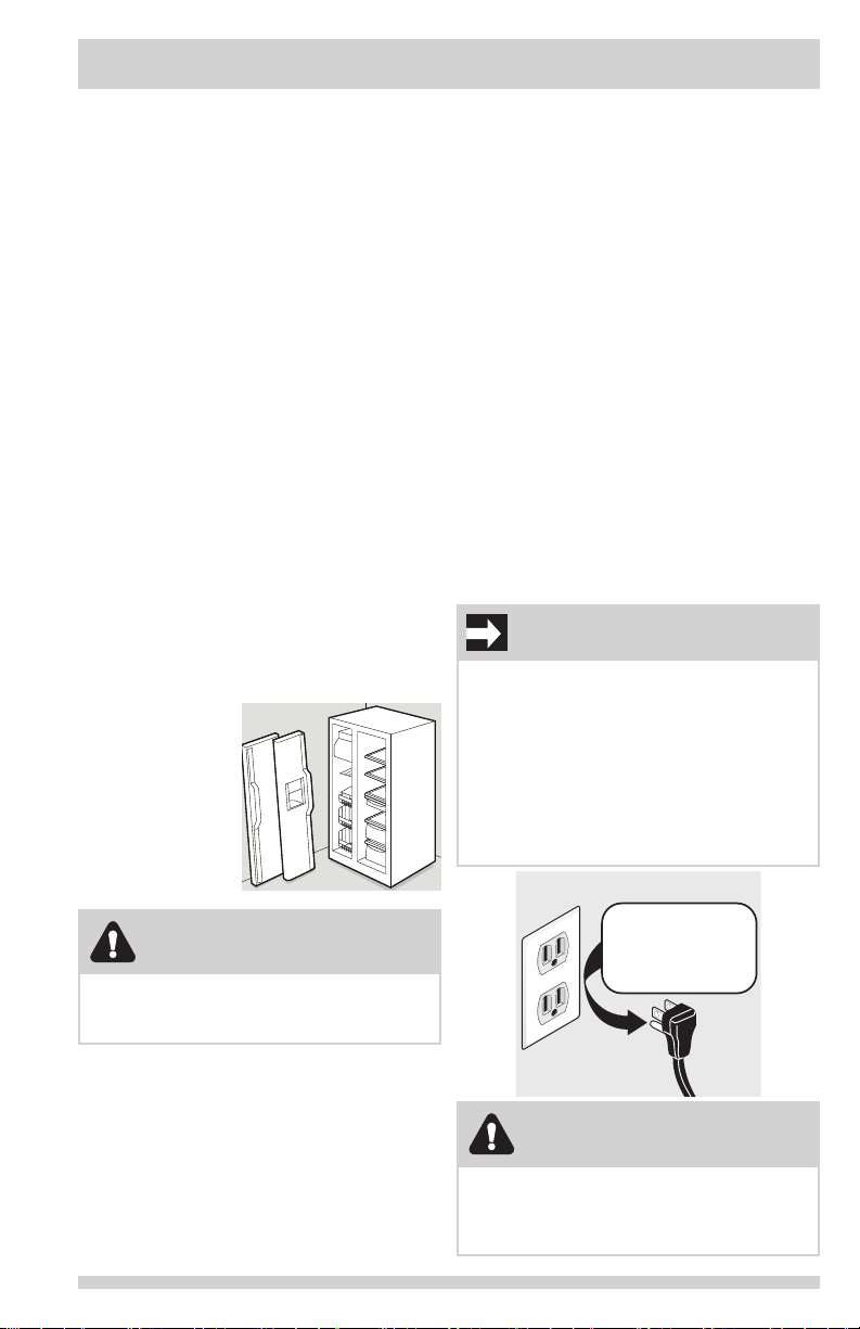
Child Safety
Destroy or recycle the carton, plastic bags, and
any exterior wrapping material immediately
after the refrigerator is unpacked. Children
should NEVER use these items to play.
Cartons covered with rugs, bedspreads, plastic
sheets or stretch wrap may become airtight
chambers, and can quickly cause suffocation.
Proper Disposal of your
Refrigerator or Freezer
Risk of child entrapment
Child entrapment and suffocation are not
problems of the past. Junked or abandoned
refrigerators or freezers are still dangerous
– even if they will sit for “just a few days”. If
you are getting rid of your old refrigerator or
freezer, please follow the instructions below to
help prevent accidents.
Proper Disposal of Refrigerators/
Freezers
We strongly encourage responsible appliance
recycling/disposal methods. Check with your utility
company or visit www.recyclemyoldfridge.com for
more information on recycling your old refrigerator.
Before you throw away your old
refrigerator/freezer:
• Remove doors.
• Leave shelves in
place so children
may not easily
climb inside.
• Have refrigerant
removed by a
qualied service
technician.
and ordinances. Consult a qualied electrician.
Avoid connecting refrigerator to a Ground
Fault Interrupter (GFI) circuit. Do not use an
extension cord or adapter plug.
• If the power cord is damaged, it should
be replaced by an authorized service
technician to prevent any risk.
• Never unplug the refrigerator by pulling on
the power cord. Always grip the plug rmly,
and pull straight out from the receptacle to
prevent damaging the power cord.
• Unplug the refrigerator before cleaning
and before replacing a light bulb to avoid
electrical shock.
• Performance may be affected if the voltage
varies by 10% or more. Operating the
refrigerator with insufcient power can
damage the compressor. Such damage is
not covered under your warranty.
• Do not plug the unit into an electrical outlet
controlled by a wall switch or pull cord to
prevent the refrigerator from being turned
off accidentally.
IMPORTANT
Pressing and holding the On/Off button for 3
seconds, located on the left side of the temperature control panel (Electronic controls),
or turning the Freezer and Fresh Food controls to “0” (Mechanical controls) will disable
your refrigerator’s cooling system, but does
not disconnect the power to the light bulb
and other electrical components. To turn off
power to your refrigerator you must unplug
the power cord from the electrical outlet.
WARNING
These guidelines must be followed to ensure
that safety mechanisms in this refrigerator
will operate properly.
Electrical information
• The refrigerator must be plugged into its
own dedicated 115 Volt, 60 Hz., 15 Amp,
AC only electrical outlet. The power cord
of the appliance is equipped with a three-
prong grounding plug for your protection
against electrical shock hazards. It must be
plugged directly into a properly grounded
three prong receptacle. The receptacle must
be installed in accordance with local codes
CAUTION
To avoid personal injury or property damage,
handle tempered glass shelves carefully. Shelves
may break suddenly if nicked, scratched, or
exposed to sudden temperature change.
3
Page 4
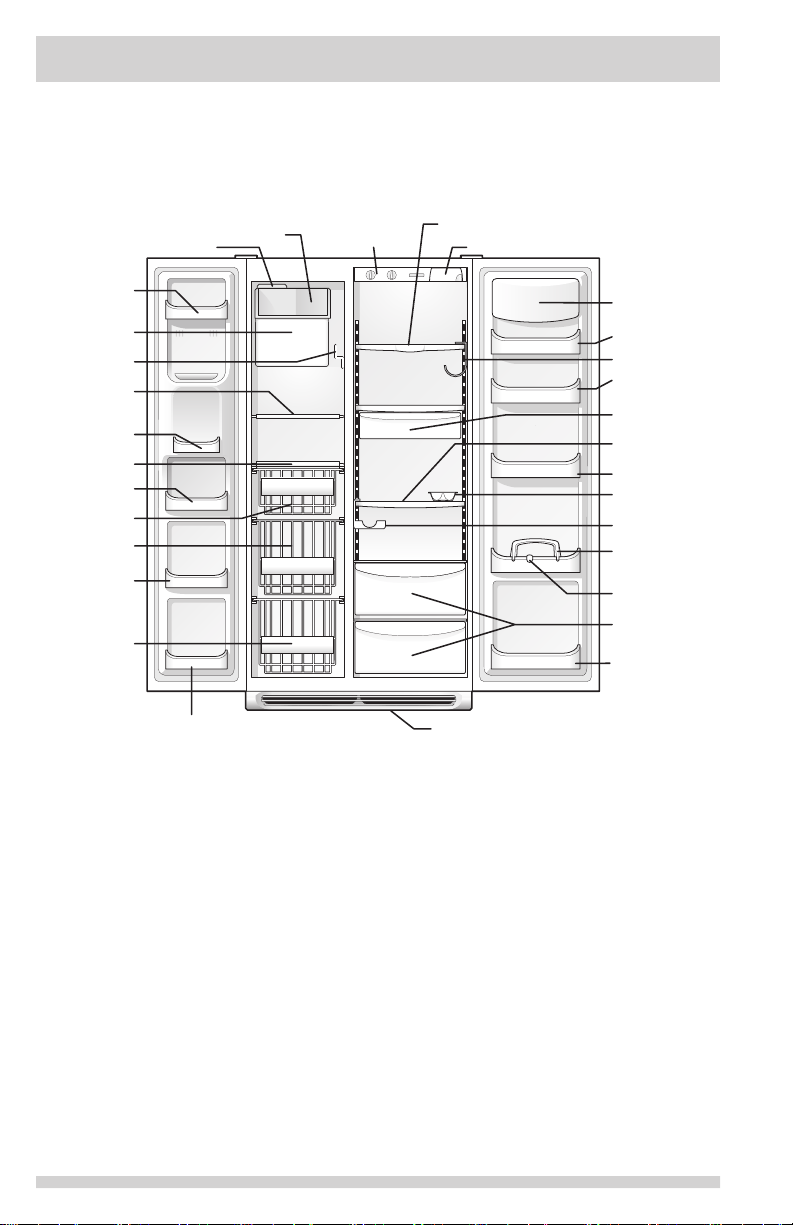
FEATURES AT A GLANCE
SpillSafe
Freezer and
Small Basket
Features may vary according to model
Door Bin
Ice Container
Pizza Shelf
Wire Shelf
Small Items
Door Bin
Wire Shelf
Door Bin
Large Basket
Door Bin
Large Basket
Ice Cream Shelf
Ice Maker
Door Bin
Refrigerator
Controls
Sliding Shelf
Toe Grille
TM
Water Filter
Dairy Door
Door Bin
Wine Rack
Door Bin
Meat Keeper
and Cover
TM
SpillSafe
Fixed Shelf
Door Bin
Egg Tray
Special Item
Rack
Tall Bottle
Retainer
Snugger
Crisper Pan
and Cover
Fixed Door Bin
4
Page 5
INSTALLATION
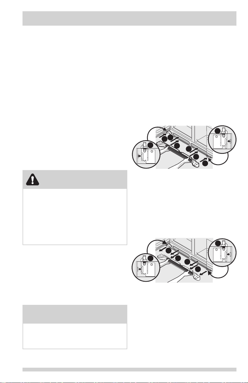
Installing Toe Grille
Removing Toe Grille
This Use & Care Guide provides general
operating instructions for your model. Use
the refrigerator only as instructed in this
Use & Care Guide. Before starting the
refrigerator, follow these important rst
steps.
Location
• Choose a place that is near a grounded
electrical outlet. Do Not use an extension
cord or an adapter plug.
• If possible, place the refrigerator out of
direct sunlight and away from the range,
dishwasher or other heat sources.
• The refrigerator must be installed on a oor
that is level and strong enough to support
a fully loaded refrigerator.
• Consider water supply availability for
models equipped with an automatic ice
maker. If you do not hook up water to
the refrigerator, remember to turn the ice
maker off.
CAUTION
Do Not install the refrigerator where the
temperature will drop below 55°F (13°C) or
rise above 110°F (43°C). The compressor
will not be able to maintain proper
temperatures inside the refrigerator.
Do Not block the toe grille on the lower front
of your refrigerator. Sufcient air circulation
is essential for the proper operation of your
refrigerator.
Installation
Installation clearances
• Allow the following clearances for ease
of installation, proper air circulation, and
plumbing and electrical connections:
Sides & Top
Back 1 inch
3
/8 inch
Toe Grille Installation and
Removal
To install toe grille
1 Open both doors. Slide left and right
sides of toe grille over lower hinges of
refrigerator.
2 While pushing toe grille rmly against
cabinet, fasten bottom clips of toe grille to
cabinet.
3 Fasten top clips to cabinet.
4 Close the doors. Fasten right and left side
clips into groove of bottom hinge.
4
3
1
4
To remove toe grille
1 With both doors closed, unfasten right
and left side clips of toe grille from bottom
hinge groove.
2 Open both doors. Press rmly on top of
toe grille until top of toe grille pops off.
3 Pull toe grille outward toward your body
and off of lower hinges.
1
2
3
2
1
1
2
3
2
3
NOTE
If your refrigerator is placed with the door
hinge side against a wall, you may have to
allow additional space so the door can be
opened wider.
5
Page 6

INSTALLATION
9/16"
(14 mm)
Max
Raise
Open Door
Door Opening
NOTE
The refrigerator doors are designed to shut
by themselves within a 20 degree opening.
Your refrigerator should be positioned to
allow easy access to a counter or table when
removing food. For best use of drawers and
freezer baskets, the refrigerator should be
in a position where both the refrigerator and
freezer doors can be fully opened.
Guidelines for nal positioning of
your refrigerator:
• All four corners of the cabinet must rest
rmly on the oor.
• The cabinet should be level at the front
and rear.
• The sides should tilt ¼ inch (6 mm) from
front to back (to ensure that doors close
and seal properly).
• Doors should align with each other and be
level.
All of these conditions can be
met by raising or lowering the
adjustable front rollers.
To level the cabinet using the front rollers:
1 Open both doors and remove the toe grille
(see “Toe Grille Installation and Removal”
in the “Installation” section).
2 Close the doors and use a at-blade
screwdriver or 3/8 inch socket wrench to
raise or lower the front rollers.
3 Ensure both doors are bind-free with their
seals touching the cabinet on all four sides.
To level the doors using the adjustable
lower hinge:
NOTE
Some models will not have a set screw. For
those models follow steps 2 through 4.
1 Before leveling either door, remove set
screw that locks door height into position.
(The door cannot be adjusted without set
screw removed).
2 If the refrigerator door is lower than the
freezer door, raise the refrigerator door by
turning the adjustment screw clockwise
using a 7/16 inch wrench. (See illustration.)
3 If the freezer door is lower than the
refrigerator door, raise the freezer door by
turning the adjustment screw clockwise
using a 7/16 inch wrench. (See illustration.)
Door
Raise
Door
4 After leveling, verify door stop contacts
lower hinge and top of door does
not contact upper hinge through full
movement of door (from fully closed to
fully open).
5 Reinstall set screw, locking the door height.
Door
Raise
Door
Door Stop
Flange
7/16" Wrench and
3/32" Hex Key (some models)
6 Replace the toe grille by tting it into
place (see “Toe Grille Installation and
Removal” in the “Installation” section).
Hinge Flange
Set Screw
(some models)
Hinge
6
Page 7
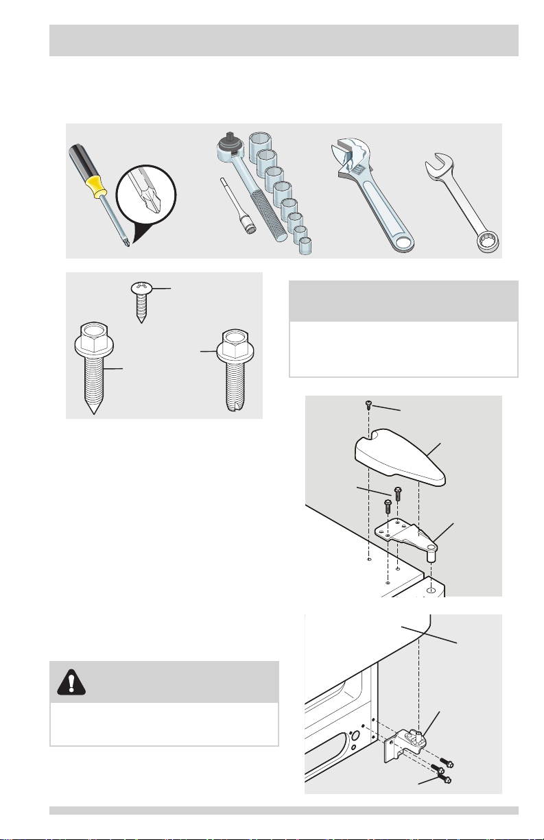
DOOR REMOVAL INSTRUCTIONS
Getting through narrow spaces
If your refrigerator will not t through an entrance area, you can reduce its size by removing the
doors. Check rst by measuring the entrance.
Tools Necessary:
AND
Top Hinge
Cover
Screw
Bottom
Hinge
Screw
Top
Hinge
Screw
1. Disconnect electrical supply.
2. Open both doors, then remove toe grille.
3. Close doors.
To Remove Refrigerator Door:
1. Remove top hinge cover screw on
refrigerator door and remove cover.
2. Trace around hinge with soft lead pencil.
This will make it easier to realign doors
when they are replaced.
3. Remove top hinge and lift refrigerator
door off bottom hinge pin. Set door aside.
4. Remove bottom hinge, if necessary.
5. Reverse this procedure to reinstall
refrigerator door.
OR OR
NOTE
Before you begin, turn Freezer and Fresh
Food controls to “O” and remove electrical
power cord from wall outlet. Remove any
food from door shelves.
Cover Screw
Top
Hinge
Cover
Hinge
Screws
Top
Hinge
Door
CAUTION
Be sure doors are set aside in a secure
position where they cannot fall and cause
personal injury.
Screws
Hinge
Assembly
7
Page 8
DOOR REMOVAL INSTRUCTIONS
To Disconnect
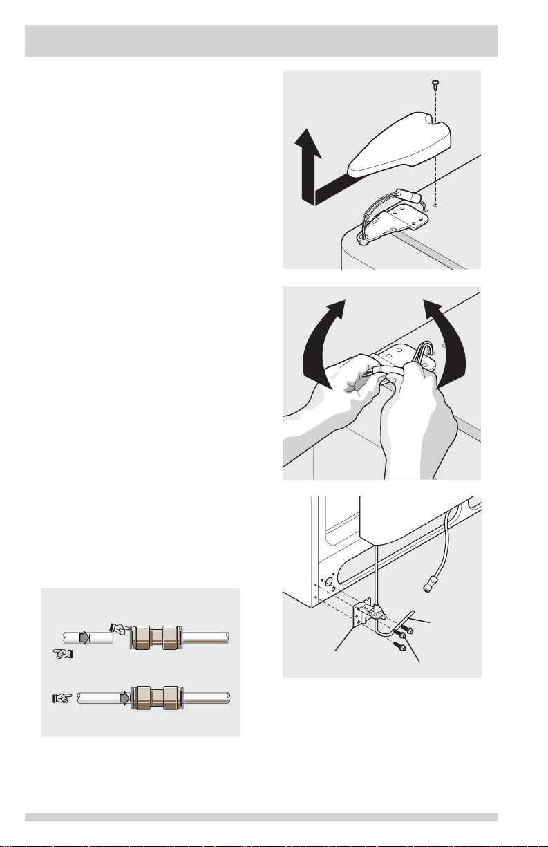
To Remove Freezer Door:
1. Disconnect water line coming from lower
hinge of freezer door at connection
located under front of freezer: Press outer
ring against face of tting, then pull to
remove tube.
2. Remove top hinge cover screw on freezer
door and remove cover.
3. Disconnect wiring harness connector plug
at top hinge: place your thumbs on at
sides of each connector and bend both
parts back and forth, then with rm grasp,
pull both pieces apart.
4. Trace around hinge with soft lead pencil.
This will make it easier to realign doors
when they are replaced.
5. Remove top hinge, allowing wiring harness
to pull through hinge and lift freezer door
off of bottom hinge pin. Lay door down
at to avoid kinking water line.
6. Remove bottom hinge, if necessary.
7. Reverse this procedure to reinstall freezer
door.
When both doors have been reinstalled,
connect water line by inserting tube and push
until mark touches face of tting, replace toe
grille and plug in electrical power cord. Turn
both temperature controls to center position.
Adjust settings as necessary.
1. Press outer ring against face of
fitting
2. Pull to
remove tube
To Connect
Insert tube and push until mark
touches face of fitting
8
Hinge
Assembly
Door
Screws
Water
Line
Tubing
Page 9

CONNECTING THE WATER SUPPLY
WARNING
To avoid electric shock, which can cause
death or severe personal injury, disconnect
the refrigerator from electrical power before
connecting a water supply line to the
refrigerator.
CAUTION
To Avoid Property Damage:
• Copper or Stainless Steel braided tubing
is recommended for the water supply
line. Water supply tubing made of ¼
inch plastic is not recommended to be
used. Plastic tubing greatly increases
the potential for water leaks, and the
manufacturer will not be responsible for
any damage if plastic tubing is used for
the supply line.
• DO NOT install water supply tubing in
areas where temperatures fall below
freezing.
• Chemicals from a malfunctioning softener
can damage the ice maker. If the ice
maker is connected to soft water, ensure
that the softener is maintained and
working properly.
• A shutoff valve to connect the water supply
line to your household water system. DO
NOT use a self-piercing type shutoff valve.
• A compression nut and ferrule (sleeve) for
connecting a copper water supply line to the
ice maker inlet valve.
NOTE
Check with your local building authority for
recommendations on water lines and associated materials prior to installing your new
refrigerator.
IMPORTANT
Ensure that your water supply line connections comply with all local plumbing codes.
Before Installing The Water Supply Line,
You Will Need:
• Basic Tools: adjustable wrench, at-blade
screwdriver, and PhillipsTM screwdriver
• Access to a household cold water line with
water pressure between 30 and 100 psi.
• A water supply line made of ¼ inch
(6.4mm) OD, copper or stainless steel
tubing. To determine the length of tubing
needed, measure the distance from the
ice maker inlet valve at the back of the
refrigerator to your cold water pipe. Then
add approximately 7 feet (2.1 meters), so the
refrigerator can be moved out for cleaning
(as shown).
9
Page 10

Steel
CONNECTING THE WATER SUPPLY
To Connect Water Supply Line To Ice Maker
Inlet Valve
1. Disconnect refrigerator from electric power
source.
2. Place end of water supply line into sink or
bucket. Turn ON water supply and ush
supply line until water is clear. Turn OFF
water supply at shutoff valve.
3. Remove plastic cap from water valve inlet
and discard cap.
4. If you use copper tubing - Slide brass
compression nut, then ferrule (sleeve)
onto water supply line. Push water supply
line into water valve inlet as far as it
will go (¼ inch/6.4 mm). Slide ferrule
(sleeve) into valve inlet and nger tighten
compression nut onto valve. Tighten
another half turn with a wrench; DO NOT
over tighten. See Figure 1.
If you use braided exible stainless
steel tubing - The nut is already
assembled on the tubing. Slide nut onto
valve inlet and nger tighten nut onto valve.
Tighten another half turn with a wrench; DO
NOT over tighten. See Figure 2.
5. With steel clamp and screw, secure water
supply line (copper tubing only) to rear
panel of refrigerator as shown.
6. Coil excess water supply line (copper tubing
only), about 2½ turns, behind refrigerator
as shown and arrange coils so they do not
vibrate or wear against any other surface.
7. Turn ON water supply at shutoff valve and
tighten any connections that leak.
8. Reconnect refrigerator to electrical power
source.
9. To turn ice maker on, lower wire signal
arm (side mounted) or set the ice maker’s
On/Off power switch to the “I” position
(rear mounted).
IMPORTANT
After connecting the water supply, refer to
“How to Prime the Water Supply System”
for important information about priming an
empty water supply system.
Your refrigerator’s water supply system
includes several tubing lines, a water lter,
a water valve, and a water tank. To ensure
that your water dispenser works properly,
this system must be completely lled with
water when your refrigerator is rst con-
nected to the household water supply line.
Plastic Water
Tubing to Ice
Maker Fill
Tube
Clamp
Brass
Compression
Nut
Ferrule
(Sleeve)
Copper
water line
Water Valve
Bracket
Valve Inlet
Water Valve
Copper water line
from household
water supply
(Include enough tubing in loop to allow
moving refrigerator out for cleaning.)
Figure 1
Plastic Water Tubing
to Ice Maker
Fill Tube
Steel
Clamp
Braided
Flexible
Stainless
Steel
Water Line
Water Valve
Bracket
Valve Inlet
Water Valve
6 ft (1.8 Meters) Braided flexible
stainless steel water line from
household water supply.
(Include enough tubing in loop to allow
moving refrigerator out for cleaning.)
Figure 2
10
Page 11

CONTROLS
NOTE
When changing control settings, wait 24 hours for the temperature to stabilize before making
additional changes.
Allowing Cooling Time Before Use
To ensure safe food storage, allow your refrigerator to operate with the doors closed for at least
8 to 12 hours before placing food inside. During this cooling period, you do not need to adjust
the controls, which are preset at the factory.
Setting Cooling Temperatures
Your refrigerator comes with a state-of-the-art electronic digital control system. The system’s
control panel is located at the top of the the fresh food compartment.
The two digital displays on the left half of the control panel indicate the current settings
or temperatures of your freezer and fresh food compartments. The models with a 2-digit
temperature display are for reference only, and do not display the current accurate compartment
temperature. Should you desire to see what the current accurate temperature is, place a
separate thermometer inside the freezer or fresh food compartment in the desired location.
NOTE
The advanced electronic control system in your refrigerator includes additional display modes
that service professionals can use to rapidly diagnose performance issues.
(Single Digit Display - Features may vary according to model.)
11
Page 12

CONTROLS
TEMPERATURE ADJUSTMENT
To adjust the temperature to a higher or lower setting, press the Up (Cold) or Down (Colder)
button closest to the display. The rst time you press the button, the display shows current
setting you entered. Each press of the button after that changes the setting by one.
The display shows your new setting momentarily, then changes back to the current temperature.
Temperature Adjustment
If Fresh Food compartment is too
warm
If Fresh Food compartment is
too cold
If Freezer compartment is too
warm
If Freezer compartment is too
cold
IF TEMPERATURE DISPLAYS FLASH...
If ever you see both temperature displays continuously ashing, it may indicate that the control
system has detected a performance problem. Call your service representative, who can interpret
the ashing message.
To maintain temperatures, a fan circulates air in the refrigerator and freezer compartments. For
good circulation, do not block cold air vents with food items.
Adjust Fresh Food control one
degree colder by pressing Down
(Colder) button.
Adjust Fresh Food control one
degree warmer by pressing the Up
(Cold) button.
Adjust Freezer control one degree
colder by pressing Down (Colder)
button.
Adjust Freezer control one degree
warmer by pressing the Up (Cold)
button.
Numeric Display
Freezer Fresh Food
Warmest 1 1
Factory Setting 6 6
Coldest 9 9
NOTE
Pressing the On/Off button on the control panel disables your refrigerator’s cooling system
but does not disconnect power to lights and other electrical components. To turn off power to
your refrigerator you must unplug the power cord from the wall outlet.
Each time you make settings on the control panel, a single audible tone acknowledges your
input.
Turning the Cooling system on and off
You can disable the cooling system in your refrigerator by pressing the On/Off button located on
the left side of the temperature control panel. To ensure that you do not accidentally turn off the
cooling system, the button does not work unless you press and hold it for three seconds. Once
you disable the cooling system, all refrigeration to the freezer and fresh food compartments
stops. To turn the cooling system back on, you must again press and hold the On/Off button for
three more seconds.
12
Page 13

CAUTION
Higher Humidity Lower Humidity
To avoid personal injury or property
damage, handle tempered glass shelves
carefully. Shelves may break suddenly if
nicked, scratched, or exposed to sudden
temperature change. See “Glass Shelves” in
Care & Cleaning Chart.
Cantilever Shelf Adjustment
Refrigerator shelves are easily adjusted to
suit individual needs. Before adjusting the
shelves, remove all food. Cantilever shelves are
supported at the back of the refrigerator.
To adjust cantilever shelves:
1 Lift front edge up.
2 Pull shelf out.
Replace the shelf by inserting the hooks at
rear of the shelf into the wall bracket. Lower
the shelf into the desired slots and lock into
position.
SpillSafeTM glass shelves (some models) catch
and hold accidental spills. In some models, the
SpillSafeTM shelves slide out for easy access to
food and for fast cleaning. The shelves slide
out independently of their mounting brackets.
Just pull the front of the shelf forward.
Shelves can be extended as far as the stopper
will allow but are not removable from their
mounting brackets.
1
2
Cantilever Glass Shelf
Cantilever Sliding
Glass Shelf
Door storage
Door bins and shelves are provided for
convenient storage of jars, bottles, and cans.
Frequently used items can be quickly selected.
Some models have door bins that can
accommodate gallon-sized plastic drink
containers and economy-sized jars and
containers. Some bins are adjustable for
maximum storage capacity.
The dairy compartment, which is warmer than
the general food storage section, is intended for
short term storage of cheese, spreads, or butter.
STORAGE FEATURES
Fresh Drawers with Humidity
Control (some models)
The fresh drawers, located under the bottom
refrigerator shelf, are designed for storing fruits,
vegetables, and other fresh produce. The fresh
drawers feature humidity control which allows you
to adjust the humidity within the drawer. This can
extend the life of fresh vegetables that keep best
in high humidity. Wash items in clear water and
remove excess water before placing them in the
crispers. Items with strong odors or high moisture
content should be wrapped before storing.
Crisper Humidity Control
NOTE
Leafy vegetables keep best when stored with
the humidity control set on Higher Humidity,
or in a drawer without a Humidity Control.
This keeps incoming air to a minimum and
maintains maximum moisture content.
Crispers
Crispers allow you the
exibility to store any
manner of items including
fruits, vegetables, nuts,
etc. Crispers do not feature
humidity controls.
Cool Drawer (some models)
1
Some models are equipped with a Cool Drawer
2
for storage of luncheon meats, spreads,
cheeses, and other deli items. This drawer
does not have a separate temperature control.
Chill Drawer (some models)
Some models are
equipped with a Chill
Drawer. Chill Drawer
temperatures can be
adjusted by sliding
the Chill Drawer
Temperature Control
in either direction. Use
this pan for short term
storage of bulk meat
items. If meats are to
be kept longer than
one or two days, they
should be frozen. The
Chill Drawer is xed and cannot be moved up or
down. If fruits or vegetables are to be stored in
the Chill Drawer, set the Chill Drawer Temperature
Control to a warmer setting to prevent freezing.
Crisper Drawer
Colder
Warmer
Chill Drawer with
Temperature Control
13
Page 14

AUTOMATIC ICE & WATER DISPENSER
Features may vary according to model.
CUBE Press the CUBE Touch Pad to get cubed ice. A green light will appear above the
CRUSH Press the CRUSH Touch Pad to get crushed ice. A green light will appear above the
LIGHT Press the LIGHT Touch Pad to turn on dispenser light. Press again to turn the
FILTER
STATUS
LOCK The Ice & Water Dispenser can be locked out to prevent unwanted use.
WATER To operate the water dispenser, press a glass against the WATER dispensing
Touch Pad. Press glass against ICE dispensing paddle as far up as possible to catch
all ice.
Touch Pad. Press glass against ICE dispensing paddle as far up as possible to catch
all ice.
light off. The light also turns on automatically when ice and/or water is dispensed.
Replace light bulb with an appliance bulb of the same wattage.
The FILTER STATUS indicator light above the Touch Pad will light up each time the
dispenser is used. The following lter light indications are:
Green The lter is still operating within its specied life cycle.
Amber The lter has reached approximately 80 percent of its useful
life. This is the recommended time to purchase a replacement
lter.
Red The lter is 100 percent used up. Change the lter as soon as
possible.
After the lter cartridge has been changed, press and hold the FILTER RESET
Touch Pad for 10-15 seconds.
NOTE: The Green, Amber and Red lights will ash when reset is completed.
To Lock Out Press the LOCK Touch Pad for 3-5 seconds. A red light will
appear above the Touch Pad.
To Unlock Press the LOCK Touch Pad for 3-5 seconds until the red light
above the Touch Pad goes out.
paddle. To stop dispensing water, pull the glass away from the dispensing paddle.
Dispensed water is not cold. For colder water, add crushed ice or cubes before
dispensing water. A drip tray located at the base of the dispenser catches small
spills and allows them to evaporate. This drip tray is removable and dishwasher
safe. Do not pour water and excess ice in this area because there is no drain.
14
Page 15

AUTOMATIC ICE & WATER DISPENSER
Priming the Water Supply System
Your refrigerator’s water supply system
includes several tubing lines, an advanced
water lter, a distribution valve bank, and a
reserve tank to ensure ample supply to the ice
and water dispenser at all times. This system
needs to be completely lled with water when
rst connected to an external supply line.
CAUTION
For proper dispenser operation, recommended
water supply pressure should fall between 30
psi and 100 psi. Excessive pressure may cause
water lter to malfunction.
To prime the water supply system:
1 Begin lling the tank by pressing and
holding a drinking glass against the water
dispenser paddle.
2 Keep the glass in this position until water
comes out of the dispenser. It may take
about 1½ minutes.
3 Continue dispensing water for about four
minutes to ush the system and plumbing
connections of any impurities (stopping to
empty the glass as necessary).
NOTE
The water dispenser has a built-in device that
shuts off the water ow after three minutes
of continuous use. To reset this shutoff device, simply release the dispenser paddle.
Ice Maker Operation & Care
The ice maker, ice bin, and dispenser feeding
mechanism are located in the top of the freezer
compartment. After the refrigerator is installed
properly and has cooled for several hours, the
ice maker can produce ice within 24 hours. It
can completely ll an ice bin in about two days.
usage conditions. Ice is produced at a rate of 8
cubes every 75 to 90 minutes.
Using the Ice Maker after Installation
Before making ice for the rst time, be sure to prime
the water supply system. Air in new plumbing lines
can result in two or three empty ice maker cycles.
Furthermore, if the system is not ushed, the rst ice
cubes may be discolored or have an odd avor.
IMPORTANT
Small ice cubes or ice chips jamming in the ice
maker may be a sign that your water lter needs
changing. If you have a side mounted ice maker
you may also experience hollow cubes partially
frozen cubes with water inside. When these
cubes are harvested, they break open and spill
water over the other ice cubes in the ice container, forming a solid mass of ice. As the water
lter nears the end of its useful life and becomes
clogged with particles, less water is delivered to
the ice maker during each cycle. The ice maker
can’t ll every cube in the ice maker mold, leading to small cubes or chips that can get caught
between the ice ejector blades and the stripper.
Remember, if your ice maker is jamming with
small ice cubes or it’s been six months or longer
since you last changed your water lter replace
the water lter with a new one. Poor quality
household water may require the lter to be
changed more frequently.
Turning the SIDE MOUNTED Ice
Maker On and Off
To begin ice production, lower the wire signal
arm to the DOWN or ON position. The ice
maker turns off automatically when the ice
container becomes full. To stop the ice maker,
raise the wire signal arm until it clicks and
locks in the UP or OFF position.
ON
Ice Production: What to Expect
How Much Ice Will a Side Mounted Ice
Maker Produce in 24 Hours?
A side mounted ice maker will produce 4 to 4.5
pounds of ice every 24 hours, depending on
usage conditions. Ice is produced at a rate of 8
cubes every 75 to 90 minutes.
How Much Ice Will a Rear Mounted Ice
Maker Produce in 24 Hours?
A rear mounted ice maker will produce 3 to 4
pounds of ice every 24 hours, depending on
OFF
Signal Arm
Wire
15
Page 16

AUTOMATIC ICE & WATER DISPENSER
Wire
Signal Arm
Off On
Turning the REAR MOUNTED Ice
Maker On and Off
Ice production is controlled by the ice maker’s
ON/OFF power switch. To gain access to the
ice maker, pull the ice cream shelf out. Press
the switch to the “O” position to turn it Off and
press it to the “I” position to turn it On. The
ice maker also has a built-in wire signal arm,
which automatically stops ice production when
the ice bin is full. DO NOT use this signal arm
to manually stop the ice maker.
IMPORTANT
Your ice maker is shipped from the factory
with the wire signal arm in the ON position
(side mounted) or with the switch turned ON
(rear mounted). To ensure proper function
of your ice maker, hook up water supply
immediately or turn ice maker OFF by lifting
the wire signal arm until it clicks and locks in
the UP position (side mounted) or turn the
On/Off switch to the Off (0) position (rear
mounted). If the ice maker is not turned off
and the water supply is not connected, the
water valve will make a loud chattering noise.
Ice Maker/Dispenser Tips
• Ice cubes stored too long may develop
an odd avor. Empty the ice container as
explained below.
• Occasionally shake the ice container to
keep ice separated.
• If your refrigerator is not connected to a
water supply or the water supply is turned
off, turn Off the ice maker.
• If you need a large quantity of ice at one
time, it is best to get cubes directly from
the ice container.
16
• The following sounds are normal when the
ice maker is operating:
- Motor running
- Ice dropping into ice container
- Water valve opening or closing
- Ice loosening from tray
- Running water
• When dispensing ice, you will hear a
snapping or clicking sound when the ice
chute opens and closes.
• Turn Off the ice maker when cleaning the
freezer and during vacations.
- If you turn Off the ice maker for a
long period of time, you should also
turn off the water supply valve.
CAUTION
Chemicals from a malfunctioning water softener
can damage the ice maker. If the water supply
to your refrigerator is softened, be sure the
softener is maintained to work properly.
Cleaning the Ice Maker
Clean the ice maker and ice bin at regular
intervals, particularly before you take a
vacation or move.
To clean the ice maker:
1 Turn Off the ice maker.
2 Remove the ice bin by lifting up and out.
3 Empty and carefully clean the ice bin with
mild detergent. Rinse with clear water. Do
not use harsh or abrasive cleaners.
4 Allow the ice bin to dry completely before
replacing in the freezer.
5 Remove ice chips and clean the ice bin
shelf and the freezer door chute.
6 Replace the ice bin. Turn On the ice maker
to resume ice production.
Remove and empty the ice storage bin if:
• An extended power failure (one hour or
longer) causes ice cubes in the ice storage
bin to melt and freeze together, jamming
the dispenser mechanism.
• You do not use the ice dispenser frequently.
Ice cubes will freeze together in the bin,
jamming the dispenser mechanism.
Remove the ice storage bin and shake to
loosen the cubes or clean as explained above.
Page 17

AUTOMATIC ICE & WATER DISPENSER
Auger
CAUTION
NEVER use an ice pick or similar sharp
instrument to break up the ice. This could
damage the ice storage bin and dispenser
mechanism.
IMPORTANT
When removing or replacing the ice bin,
DO NOT rotate the auger in the ice bin. If
the auger is accidentally rotated, you must
realign the auger by turning it in 90 degree
turns (see below) until the ice bin ts into
place with the drive mechanism. If the
auger is not properly aligned when replac-
ing the ice bin, the refrigerator will only
dispense Crushed Ice. The freezer door may
also not close properly causing warm air to
leak into the freezer.
17
Page 18

CHANGING THE FILTER
Locating the Filter
Your refrigerator is equipped with a water
ltering system. The water lter system lters
all dispensed drinking water, as well as the
water used to produce ice.
Water Filter
The water lter is located at the top right side
of the fresh food compartment.
Replacing the Water Filter
In general, you should change the water
lter every six months to ensure the highest
possible water quality. Water Filter Status
on the user interface prompts you to replace
the lter after a standard amount of water
(200 gallons/757 liters for PureSource 3TM)
has owed through the system.
If your refrigerator has not been used for a
period of time (during moving for example),
change the lter before reinstalling the
refrigerator.
Filter Cartridge
Ordering Replacement Filters
To order your replacement lters, please
contact manufacturer.
Here are the product numbers to request when
ordering:
PureSource 3
Water Filter
Part #WF3CB
TM
18
More about your Advanced
Water Filter
The PureSource 3TM ice and water
lter system is tested and certied
to NSF/ANSI Standards 42 and 53
for the reduction of claims specied
on the performance data sheet.
Do not use with water that is microbiologically
unsafe or of unknown quality without adequate
disinfection before or after the system. Systems
certied for cyst reduction may be used on
disinfected waters that may contain lterable cysts.
Test & certication results:
• Rated Capacity - 200 gallons/757 liters for
PureSource 3TM ice and water lter
• Rated service ow - .50 gallons per minute
• Operating Temp.: Min. 33°F, Max. 100°F
• Maximum Rated Pressure - 100 pounds per
square inch
• Recommended Minimum Operating
Pressure: 30 pounds per square inch
To replace your PureSource 3TM water
lter:
It is not necessary to turn the water supply off
to change the lter. Be ready to wipe up any
small amounts of water released during the
lter replacement.
1 Turn Off the ice maker.
2 Remove the lter by pushing on the end/
face of the lter.
3 Slide the old water lter cartridge straight
out of the housing and discard it.
4 Unpackage the new lter cartridge. Using
the alignment guide, slide it gently into the
lter housing until it stops against the snap-
in connector at the back of the housing.
5 Push rmly until the cartridge snaps into
place (you should hear a click as the
cartridge engages the snap-in connector).
6 Press a drinking glass against the water
dispenser while checking for any leaks at
the lter housing. Any spurts and sputters
that occur as the system purges air out of
the dispenser system are normal.
7 After lling one glass of water, continue
ushing the system for about four minutes.
8 Turn On the ice maker.
9 Press and hold the Water Filter button on the
Ice & Water Dispenser control panel for three
seconds. When the display changes from
“Red” to “Green,” the status has been reset.
Page 19

D
OR
NORMAL OPERATING SOUNDS AND SIGHTS
Understanding the Sounds you
may Hear
Your new, high-efciency refrigerator may
introduce unfamiliar sounds. These sounds
normally indicate your refrigerator is operating
correctly. Some surfaces on oors, walls, and
kitchen cabinets may make these sounds more
noticeable.
Following is a list of major components in your
refrigerator and the sounds they can cause:
A Evaporator Refrigerant through the
evaporator may create a boiling or
gurgling sound.
B Evaporator fan You may hear air being
forced through the refrigerator by the
evaporator fan.
C Defrost heater During defrost cycles,
water dripping onto the defrost heater
may cause a hissing or sizzling sound.
After defrosting, a popping sound may
occur.
D Automatic ice maker When ice has
been produced, you will hear ice cubes
falling into the ice bin.
E Electronic control & automatic
defrost control These parts can produce
a snapping or clicking sound when turning
the cooling system on and off.
F Condenser fan You may hear air being
forced through the condenser.
G Compressor Modern, high-efciency
compressors run much faster than in the
past. The compressor may have a highpitched hum or pulsating sound.
H Water valve Makes a buzzing sound each
time it opens to ll the ice maker.
I Drain pan (not removable) You may hear
water dripping into the drain pan during
the defrost cycle.
J Condenser May create minimal sounds
from forced air.
K Motorized damper May produce a light
humming during operation.
L Ice chute When dispensing ice, you will
hear a snapping or clicking sound when
the solenoid opens and closes the ice
chute.
NOTE
Energy efcient foam in your refrigerator is
not a sound insulator.
NOTE
During automatic defrost cycle, a red glow in
the back wall vents of your freezer compartment is normal.
19
Page 20

CARE & CLEANING
Protecting your investment
Keeping your refrigerator clean maintains appearance and prevents odor build-up. Wipe up any
spills immediately and clean the freezer and fresh food compartments at least twice a year.
When cleaning, take the following precautions:
• Never use CHLORIDE or cleaners with bleach to clean stainless steel.
• Do not wash any removable parts in a dishwasher.
• Always unplug the electrical power cord from the wall outlet before cleaning.
• Remove adhesive labels by hand. Do not use razor blades or other sharp instruments which
can scratch the appliance surface.
• Do not remove the serial plate.
Do not use abrasive cleaners such as window sprays, scouring cleansers, brushes, ammable
uids, cleaning waxes, concentrated detergents, bleaches or cleansers containing petroleum
products on plastic parts, interior doors, gaskets or cabinet liners. Do not use paper towels,
metallic scouring pads, or other abrasive cleaning materials or strong alkaline solutions.
NOTE
If you set your temperature controls to turn off cooling, power to lights and other electrical
components will continue until you unplug the power cord from the wall outlet.
CAUTION
• Pull the refrigerator straight out to move it. Shifting it from side to side may damage
ooring. Be careful not to move the refrigerator beyond the plumbing connections.
• Damp objects stick to cold metal surfaces. Do not touch refrigerated surfaces with wet or
damp hands.
IMPORTANT
If you store or move your refrigerator in freezing temperatures, be sure to completely drain
the water supply system. Failure to do so could result in water leaks when the refrigerator is
put back into service. Contact a service representative to perform this operation.
20
Page 21

CARE & CLEANING
Care & Cleaning Tips
Part What To Use Tips and Precautions
Interior & Door
Liners
Door Gaskets • Soap and water Wipe gaskets with a clean soft cloth.
Drawers & Bins • Soap and water Use a soft cloth to clean drawer runners and tracks.
Glass Shelves • Soap and water
Toe Grille • Soap and water
Exterior &
Handles
Exterior &
Handles
(Stainless Steel
Models Only)
• Soap and water
• Baking soda and
water
• Glass cleaner
• Mild liquid
sprays
• Mild liquid
sprays
• Vacuum
attachment
• Soap and water
• Non Abrasive
Glass Cleaner
• Soap and water
• Stainless Steel
Cleaners
Use 2 tablespoons of baking soda in 1 quart of warm
water. Be sure to wring excess water out of sponge
or cloth before cleaning around controls, light bulb or
any electrical part.
Allow glass to warm to room temperature before
immersing in warm water.
Vacuum dust from front of toe grille. Remove
toe grille (see Installation Instructions). Vacuum
backside, wipe with sudsy cloth or sponge. Rinse and
dry.
Do not use commercial household cleaners
containing ammonia, bleach or alcohol to clean
handles. Use a soft cloth to clean smooth handles.
DO NOT use a dry cloth to clean smooth doors.
Never use CHLORIDE or cleaners with bleach to
clean stainless steel.
Clean stainless steel front and handles with nonabrasive soapy water and a dishcloth. Rinse with
clean water and a soft cloth. Use a non-abrasive
stainless steel cleaner. These cleaners can be
purchased at most home improvement or major
department stores. Always follow manufacturer’s
instructions. Do not use household cleaners
containing ammonia or bleach.
Replacing Light
Bulbs
• Unplug
refrigerator
• Wear gloves
• Remove light
cover
• Replace old bulb
• Replace light
cover
• Plug in the
refrigerator
NOTE: Always clean, wipe and dry with the grain to
prevent scratching. Wash the rest of the cabinet with
warm water and mild liquid detergent. Rinse well,
and wipe dry with a clean soft cloth.
CAUTION: Wear gloves when replacing light
bulbs to avoid getting cut.
Use same wattage when replacing bulb
21
Page 22

BEFORE YOU CALL
PROBLEM CAUSE CORRECTION
AUTOMATIC ICE MAKER
Ice maker is not
making any ice.
Ice maker is not
making enough
ice.
Ice maker will not
stop making ice.
Ice cubes are
freezing together.
ICE DISPENSER
Dispenser will not
dispense ice.
Ice dispenser is
jammed.
• Ice maker wire signal
arm is in the “up” or
OFF position.
• Ice maker power
switch is Off.
• Ice maker has small
cube caught in
mechanism.
• Saddle valve on cold
water pipe is clogged
or restricted by foreign
material.
• Ice maker is producing
less ice than you
expect.
• Check to see if water
dispenser is dispensing
slower than normal.
• Ice maker wire signal arm
is being held down by
some item in the freezer.
• Ice cubes are not being
used frequently enough.
• Ice cubes are hollow
(partially frozen cubes
with water inside).
• Freezer control is set
too warm.
• Ice storage container is
empty.
• Freezer temperature is
set too warm.
• Household water line
valve is not open.
• Ice dispensing arm has
been held in for more
than 4-5 minutes.
• Ice has melted and
frozen around auger
due to infrequent
use, temperature
uctuations, and/or
power outages.
• Ice cubes are jammed
between ice maker and
back of ice container.
• Move wire signal arm to the “down” or
ON position. (side mounted)
• Turn power switch to On (“I”) position.
(rear mounted)
• Remove small cube from ice maker. The
ice and water lter cartridge may be
clogged. Replace lter cartridge.
• Turn off household water line valve.
Remove valve. Ensure that valve is not
a self-piercing saddle valve. Clean valve.
Replace valve if necessary.
• Side mounted ice maker should produce
4 to 4.5 pounds (approximately 4 quarts)
of ice every 24 hours. A rear mounted
ice maker should produce 3 to 4 pounds
(approximately 3½ quarts) of ice every 24
hours. Quick Ice option should produce up
to 50% more ice every 24 hours.
• If it is, replace the ice and water lter
cartridge.
• Move item and release wire signal arm.
Remove any ice cubes that are frozen
together over the wire signal arm.
• Remove ice container and discard ice from
container. Ice maker will produce fresh supply.
• The ice and water lter cartridge may be
clogged. Replace lter cartridge.
• Set freezer control to colder setting. Allow
24 hours for temperature to stabilize.
• When the rst supply of ice is dropped into
the container, the dispenser should operate.
• Turn freezer control to a higher setting so that
ice cubes will be made. When rst supply of
ice is made, dispenser should operate.
• Open household water line valve. Allow
sufcient time for the ice to be made. When
ice is made, the dispenser should operate.
• Motor is overloaded. Motor over load
protector will reset in approximately 3
minutes. Ice can then be dispensed.
• Remove ice container, thaw, and empty
the contents. Clean container, wipe dry,
and replace in proper position. When new
ice is made, dispenser should operate.
• Remove ice cubes that are jamming the
dispenser.
22
Page 23

BEFORE YOU CALL
PROBLEM CAUSE CORRECTION
OPENING/CLOSING OF DOORS/DRAWERS
Door(s) will not
close.
Drawers are
difcult to move.
RUNNING OF REFRIGERATOR
Compressor does
not run.
Refrigerator runs
too much or too
long.
Compressor
goes off and on
frequently.
• Door was closed too
hard, causing other
door to open slightly.
• Refrigerator is not level.
It rocks on the oor
when moved slightly.
• Refrigerator is touching
a wall or cabinet.
• Food is touching shelf
on top of drawer.
• Track that drawers
slide on is dirty.
• Freezer control is set
to “OF” or “0”.
• Refrigerator is in
defrost cycle.
• Plug at electrical outlet
is disconnected.
• House fuse blown or
tripped circuit breaker.
• Power outage.
• Room or outside
weather is hot.
• Doors are opened too
frequently or too long.
• Fresh Food/freezer
door may be slightly
open.
• Freezer control is set
too cold.
• Fresh Food/freezer
gasket is dirty, worn,
cracked, or poorly tted.
• Condenser is dirty.
• Thermostat keeps
the refrigerator at a
constant temperature.
• Close both doors gently.
• Ensure oor is level and solid, and can
adequately support the refrigerator. Contact a
carpenter to correct a sagging or sloping oor.
• Ensure oor is level and solid, and can
adequately support the refrigerator. Contact a
carpenter to correct a sagging or sloping oor.
• Remove top layer of items in drawer.
• Ensure drawer is properly installed on track.
• Clean drawer, rollers, and track. See Care
& Cleaning.
• Set freezer control.
• This is normal for a fully automatic defrost
refrigerator. The defrost cycle occurs
periodically, lasting about 30 minutes.
• Ensure plug is tightly pushed into outlet.
• Check/replace fuse with a 15 amp timedelay fuse. Reset circuit breaker.
• Check house lights. Call local electric
company.
• It’s normal for the refrigerator to work
longer under these conditions.
• Warm air entering the refrigerator causes
it to run more. Open doors less often.
• Ensure refrigerator is level. Keep food
and contains from blocking door. See
PROBLEM column OPENING/CLOSING
OF DOORS/DRAWERS.
• Set Fresh Food control to warmer
setting until refrigerator temperature
is satisfactory. Allow 24 hours for
temperature to stabilize.
• Clean or change gasket. Leaks in door
seal will cause refrigerator to run longer in
order to maintain desired temperatures.
• Clean condenser. See Care & Cleaning.
• This is normal. Refrigerator goes on and
off to keep temperature constant.
23
Page 24

BEFORE YOU CALL
PROBLEM CAUSE CORRECTION
DIGITAL TEMPERATURE DISPLAY
Digital temperature
displays are
ashing.
WATER DISPENSER
Dispenser will not
dispense water.
Water has an odd
taste and/or odor.
Water pressure is
extremely low.
WATER/MOISTURE/FROST INSIDE REFRIGERATOR
Moisture collects
on inside of
refrigerator walls.
Water collects on
bottom side of
drawer cover.
Water collects in
bottom of drawer.
WATER/MOISTURE/FROST OUTSIDE REFRIGERATOR
Moisture collects
on outside of
refrigerator or
between doors.
• Electronic control
system has detected a
performance problem.
• Household water line
valve is not open.
• Ice and water lter
cartridge is clogged.
• Filter not fully installed.
• Water has been in the
tank for a period of
time.
• Unit not properly
connected to cold
water line.
• Cut-off and cut-on
pressures are too low
(well systems only).
• Reverse osmosis
system is in
regenerative phase.
• Weather is hot and
humid.
• Door is slightly open.
• Vegetables contain
and give off moisture.
• Washed vegetables
and fruit drain while in
the drawer.
• Weather is humid.
• Door is slightly open,
causing cold air from
inside refrigerator to
meet warm air from
outside.
• Call your Frigidaire service representative,
who can interpret any messages or number
codes ashing on the digital displays.
• Open household water line valve. See
PROBLEM column AUTOMATIC ICE MAKER.
• Replace lter cartridge.
• Push lter in until you hear a “click”.
• Draw and discard 10-12 glasses of water
to freshen the supply and completely
rinse out the tank.
• Connect unit to cold water line that
supplies water to the kitchen faucet.
• Have someone turn up the cut-off and
cut-on pressure on the water pump
system (well systems only).
• It is normal for a reverse osmosis
system to be below 20 psi during the
regenerative phase.
• The rate of frost buildup and internal
sweating increases.
• See PROBLEM column OPENING/
CLOSING OF DOORS/DRAWERS.
• It is not unusual to have moisture on the
bottom side of the cover.
• Move humidity control (some models) to
lower setting.
• Dry items before putting them in the
drawer. Water collecting in bottom of
drawer is normal.
• This is normal in humid weather. When
humidity is lower, the moisture should
disappear.
• See PROBLEM column OPENING/
CLOSING OF DOORS/DRAWERS.
24
 Loading...