

Page 1
installation instructions
G_s
Instrucciones de Instalaci6n
Printed in U.S.A.
P/N 137153400A (0903)
Page 2
Table of Contents
Important Safety Instructions ................................................ 2
Pre-installation Requirements ................................................ 2
Installation Requirements .................................................. 3-7
Installed Dimensions ............................................................. 8
Installation Instructions ................................................... 9-11
Reversing door .................................................................... 12
Accessories/Replacement parts ............................................ 12
Espa_ol............................................................................... 13
Important Safety Instructions
Foryour safety the information in this manual must be followed to minimize the risk of fire or explosion or to
prevent property damage, personal injury or loss of life. Do not store or use gasoline or other flammable vapors and liquids in
the vicinity of this or any other appliance.
Recognize safety symbols, words and labels
Safety items throughout this manual are labeled with a
WARNING or CAUTION based on the risk type as described:
- RISK OF FIRE - Read all of the following instructions before installing and using this appliance:
• Destroy the carton and plastic bags after the dryer is unpacked. Children might use them for play. Cartons covered with
rugs, bedspreads, or plastic sheets can become airtight chambers causing suffocation. Placeall materials in a garbage
container or make materials inaccessible to children.
Clothes dryer installation and service must be performed by a qualified installer, service agency or the gas supplier.
Install the clothes dryer according to the manufacturer's instructions and local codes.
The electrical service to the dryer must conform with local codes and ordinances and the latest edition of the National
Electrical Code, ANSI/NFPA70, or in Canada, the Canadian electrical code C22.1 part 1.
The gas serviceto the dryer must conform with local codes and ordinances and the latest edition of the National Fuel Gas
Code ANSI Z223.1, or in Canada, CAN/ACG B149.1-2000.
The dryer is designed under ANSI Z 21.5.1 or ANSI/UL 2158 - CAN/CSA C22.2 No. 112 (latest editions) for HOME USE
only. This dryer is not recommended for commercial applications such as restaurants, beauty salons, etc.
Do not install a clothes dryer with flexible plastic venting material. Flexible venting materials are known to collapse, be eas-
ily crushed and trap lint. These conditions will obstruct clothes dryer airflow and increase the risk of fire.
The instructions in this manual and all other literature included with this dryer are not meant to cover every possible
condition and situation that may occur. Good safe practice and caution MUST be applied when installing, operating and
maintaining any appliance.
_This symbol alerts you to situations that
may cause serious body harm, death or
property damage.
This symbol alerts you to situations that may
-- cause bodily injury or property damage.
WHAT TO DO IF YOU SMELL GAS:
Do not try to light any appliance.
Do not touch any electrical switch; do not use any phone in your building.
Clear the room, building or area of all occupants.
Immediately call your gas supplier from a neighbor's phone. Follow the gas supplier's instructions.
If you cannot reach your gas supplier, call the fire department.
Save these instructions for future reference.
Pre-lnstallation Requirements
Tools and materials needed for installation:
Adjustable pliers
Phillips, straight, & square bit screw-
drivers
Adjustable wrench
Pipe wrench for gas supply (gas dryer)
LP-resistant thread tape (for natural
gas or LPsupply, gas dryer)
Carpenter's level
External vent hood
4-inch (10.2 cm), rigid metal or semi-
rigid metal exhaust duct work
3-wire or 4-wire 240 volt cord kit
(electric dryer)
4 in. (10.2 cm) clamp
Gas line shutoff valve (gas dryer)
1/2NPT union flare adapters (x2) and
flexible gas supply line (gas dryer)
Metal foil tape (not duct tape)
Page 3
Electrical System Requirements
Because of potentially inconsistent voltage capabilities, the use of this dryer with power created by gas powered gen-
erators, solar powered generators, wind powered generators or any other generator other than the local utility company is not
recommended.
Electrical requirements for electric dryer
CIRCUIT- Individual 30 amp. branch circuit fused with 30 amp. time delay fuses or circuit breakers. Use separately fused
circuits for washer and dryer. DO NOT operate a washer and a dryer on the same circuit.
POWERSUPPLY- 3-wire or 4-wire, 240 volt, single phase, 60 Hz, Alternating Current.
This dryer is internally grounded to neutral unless it was manufactured for sale in Canada. Grounding through
the neutral link is prohibited for: (1) new branch circuit installations, (2) mobile homes, (3) recreational vehicles, and (4) areas
where local codes do not permit grounding through the neutral.
OUTLETRECEPTACLE- NEMA 10-30R or NEMA 14-30R receptacle to be located so the power supply cord isaccessiblewhen the
dryer is in the installed position.
GROUNDING CONNECTION - See "Grounding requirements" in Electrical Installation section.
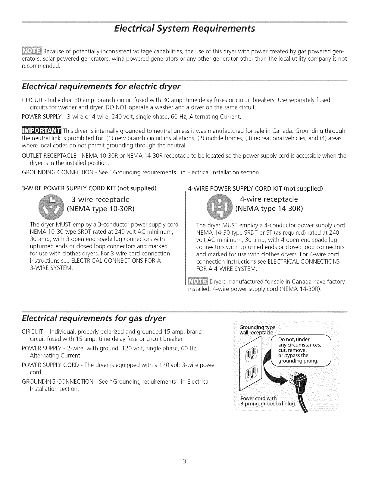
3-WIRE POWER SUPPLY CORD KIT (not supplied)
4-WIRE POWER SUPPLY CORD KIT (not supplied)
3-wire receptacle
(NEMA type 10-30R)
The dryer MUST employ a 3-conductor power supply cord
NEMA 10-30 type SRDTrated at 240 volt AC minimum,
30 amp, with 3 open end spade lug connectors with
upturned ends or closed loop connectors and marked
for use with clothes dryers. For3-wire cord connection
instructions see ELECTRICALCONNECTIONSFORA
3-WIRE SYSTEM.
The dryer MUST employ a 4-conductor power supply cord
NEMA 14-30 type SRDTor ST(as required) rated at 240
volt AC minimum, 30 amp, with 4 open end spade lug
connectors with upturned ends or closed loop connectors
and marked for use with clothes dryers. For4-wire cord
connection instructions see ELECTRICALCONNECTIONS
FORA 4-WIRE SYSTEM.
Dryers manufactured for sale in Canada have factory-
installed, 4-wire power supply cord (NEMA 14-30R).
Electrical requirements for gas dryer
CIRCUIT- Individual, properly polarized and grounded 15 amp. branch
circuit fused with 15 amp. time delay fuse or circuit breaker.
POWERSUPPLY- 2-wire, with ground, 120 volt, single phase, 60 Hz,
Alternating Current.
POWERSUPPLYCORD - The dryer is equipped with a 120 volt 3-wire power
cord.
4-wire receptacle
(NEMA type 14-30R)
Groundingtype
wallreceptacle
f
Do not, under
any circumstances,
cut, remove,
or bypassthe
grounding prong.
GROUNDING CONNECTION - See "Grounding requirements" in Electrical
Installation section.
Powercord with
3-prong grounded plug
Page 4
Gas supply requirements
- EXPLOSION HAZARD - Uncoated copper
tubing will corrode when subjected to natural gas, causing
gas leaks. Use ONLY black iron, stainless steel, or plastic-coat-
ed brass piping for gas supply.
1. Installation MUST conform with local codes, or in the
absence of local codes, with the National FuelGas Code,
ANSI Z223.1 (latest edition).
2. The gas supply line should be 1/2 inch (1.27 cm) pipe.
3. If codes allow, flexible metal tubing may be used to
connect your dryer to the gas supply line. The tubing
MUST be constructed of stainlesssteel or plastic-coated
brass.
4. The gas supply line MUST have an individual shutoff valve.
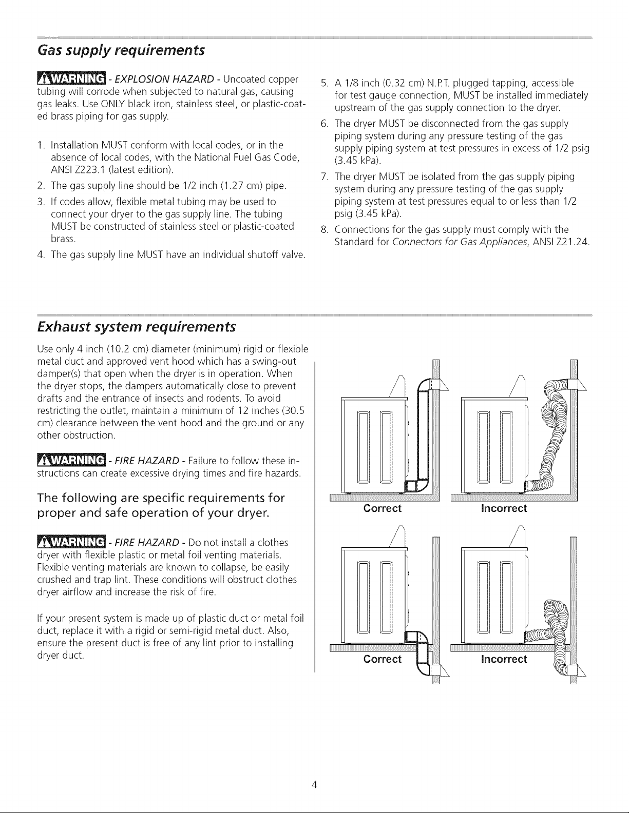
Exhaust system requirements
Use only 4 inch (10.2 cm) diameter (minimum) rigid or flexible
metal duct and approved vent hood which has a swing-out
damper(s) that open when the dryer is in operation. When
the dryer stops, the dampers automatically close to prevent
drafts and the entrance of insects and rodents. Toavoid
restricting the outlet, maintain a minimum of 12 inches (30.5
cm) clearance between the vent hood and the ground or any
other obstruction.
5. A 1/8 inch (0.32 cm) N.RT.plugged tapping, accessible
for test gauge connection, MUST be installed immediately
upstream of the gas supply connection to the dryer.
6. The dryer MUST be disconnected from the gas supply
piping system during any pressure testing of the gas
supply piping system at test pressures in excess of 1/2 psig
(3.45 kPa).
7. The dryer MUST be isolated from the gas supply piping
system during any pressure testing of the gas supply
piping system at test pressures equal to or lessthan 1/2
psig (3.45 kPa).
8. Connections for the gas supply must comply with the
Standard for Connectors for Gas Appliances, ANSI Z21.24.
- FIRE HAZARD - Failure to follow these in-
structions can create excessive drying times and fire hazards.
The following are specific requirements for
proper and safe operation of your dryer.
- FIRE HAZARD - Do not install a clothes
dryer with flexible plastic or metal foil venting materials.
Flexible venting materials are known to collapse, be easily
crushed and trap lint. These conditions will obstruct clothes
dryer airflow and increase the risk of fire.
If your present system is made up of plastic duct or metal foil
duct, replace it with a rigid or semi-rigid metal duct. Also,
ensure the present duct isfree of any lint prior to installing
dryer duct.
Correct Incorrect
Page 5
Exhaust system requirements, continued
- FIRE HAZARD - A clothes dryer must be
exhausted outdoors. Do not exhaust dryer into a chimney, a
wall, a ceiling, an attic, a crawl space or any concealed space
of a building. A clothes dryer produces combustible lint. If
the dryer is not exhausted outdoors, some fine lint will be
expelled into the laundry area. An accumulation of lint in any
area of the home can create a health and fire hazard.
The dryer must be connected to an exhaust outdoors.
Regularly inspect the outdoor exhaust opening and remove
any accumulation of lint around the outdoor exhaust opening
and in the surrounding area.
- FIRE HAZARD -
• Do not allow combustible materials (for example: clothing,
draperies/curtains, paper) to come in contact with exhaust
system. The dryer MUST NOT be exhausted into a chim-
ney, a wall, a ceiling, or any concealed space of a building
which can accumulate lint, resulting in a fire hazard.
Do not screen the exhaust ends of the vent system, or use
any screws, rivets or other fasteners that extend into the
duct to assemble the exhaust system. Lint can become
caught in the screen, on the screws or rivets, clogging the
duct work and creating a fire hazard aswell as increasing
drying times. Use an approved vent hood to terminate the
duct outdoors, and seal all joints with duct tape. All male
duct pipe fittings MUST be installed downstream with the
flow of air.
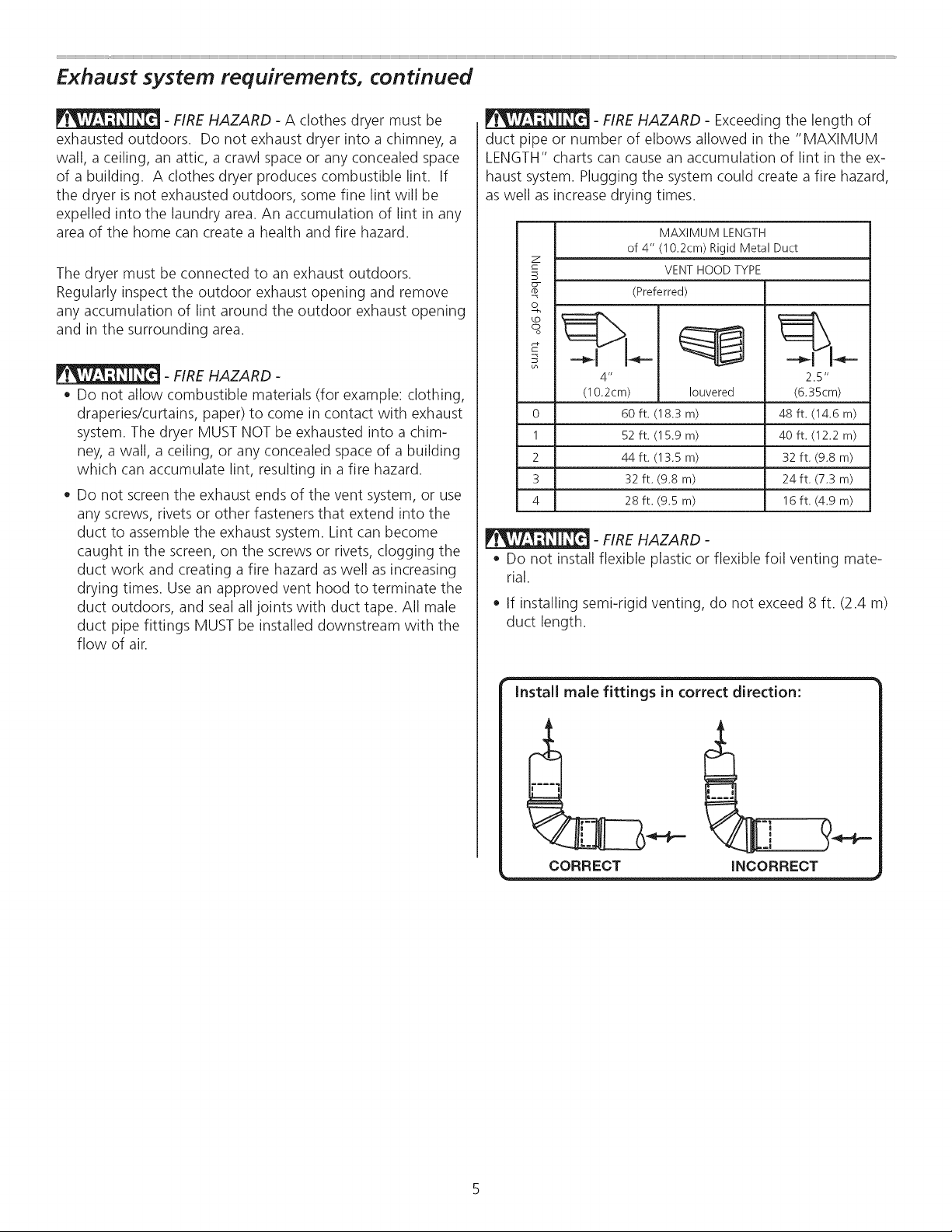
- FIRE HAZARD - Exceeding the length of
duct pipe or number of elbows allowed in the "MAXIMUM
LENGTH" charts can cause an accumulation of lint in the ex-
haust system. Plugging the system could create a fire hazard,
as well as increase drying times.
MAXIMUM LENGTH
of 4" (10.2cm) Rigid Metal Duct
VENT HOOD TYPE
o
o_
0
1
2
3
4
o
(lO.2cm)
(Preferred)
4"
60 ft. (18.3m)
52 ft. (15.9 m)
44 ft. (13.5 m)
32 ft. (9.8 m)
28 ft. (9.5 m)
Iouvered
2.5"
(6.35cm)
48 ft. (14.6 m)
40 ft. (12.2 m)
32 ft. (9.8 m)
24 ft. (7.3 m)
16 ft. (4.9 m)
- FIRE HAZARD -
Do not install flexible plastic or flexible foil venting mate-
rial.
If installing semi-rigid venting, do not exceed 8 ft. (2.4 m)
duct length.
Install male fittings in correct direction:
CORRECT INCORRECT
Page 6
Exhaust system requirements, continued
In installations where the exhaust system is not described in
the charts, the following method must be used to determine
if the exhaust system is acceptable:
1. Connect an inclined or digital manometer between the
dryer and the point the exhaust connects to the dryer.
2. Set the dryer timer and temperature to air fluff (cool
down) and start the dryer.
3. Read the measurement on the manometer.
4. The system back pressure MUST NOT be higher than
0.75 inches of water column. If the system back pressure
is lessthan 0.75 inches of water column, the system is
acceptable. If the manometer reading is higher than .075
inches of water column, the system istoo restrictive and
the installation is unacceptable.
Although vertical orientation of the exhaust system is
acceptable, certain extenuating circumstances could affect
the performance of the dryer:
• Only the rigid metal duct work should be used.
Venting vertically through a roof may expose the exhaust
system to down drafts causing an increase in vent
restriction.
Running the exhaust system through an uninsulated area
may cause condensation and faster accumulation of lint.
Compression or crimping of the exhaust system will cause
an increase in vent restriction.
The exhaust system should be inspected and cleaned a
minimum of every 18 months with normal usage. The
more the dryer is used, the more often you should check
the exhaust system and vent hood for proper operation.
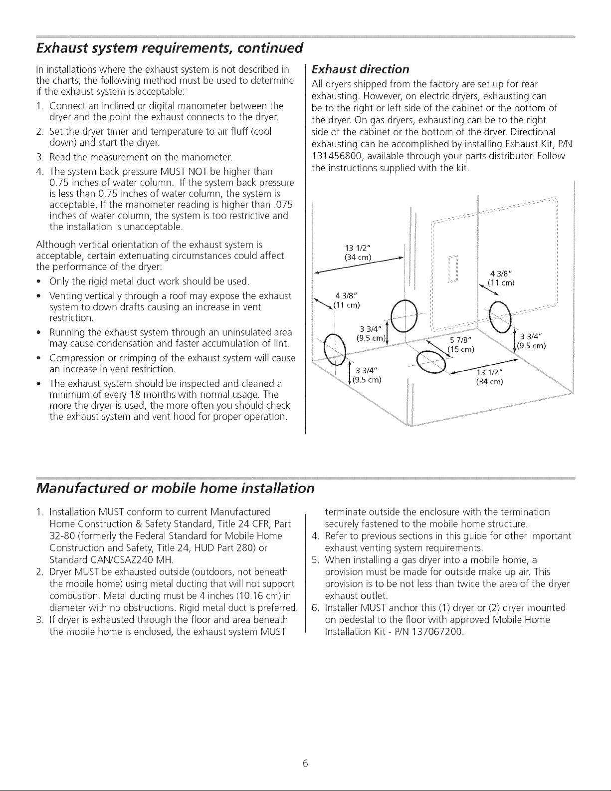
Exhaust direction
All dryers shipped from the factory are set up for rear
exhausting. However, on electric dryers, exhausting can
be to the right or left side of the cabinet or the bottom of
the dryer. On gas dryers, exhausting can be to the right
side of the cabinet or the bottom of the dryer. Directional
exhausting can be accomplished by installing Exhaust Kit, P/N
131456800, available through your parts distributor. Follow
the instructions supplied with the kit.
i," !!
13 1/2"
iii
.... ii
4 3/8"
(11 cm)
4 3/8"
11 crn)
3 3/4"
(9.5 cm
\
3 3/4" 13 1/2"
(9.5 cm) : (34 cm)
',L.... 5 7/8" '_3 3/4"
(15 cm) ,(9.5 cm)
Manufactured or mobile home installation
1. Installation MUST conform to current Manufactured
Home Construction & Safety Standard, Title 24 CFR, Part
32-80 (formerly the Federal Standard for Mobile Home
Construction and Safety, Title 24, HUD Part 280) or
Standard CAN/CSAZ240 MH.
2. Dryer MUST be exhausted outside (outdoors, not beneath
the mobile home) using metal ducting that will not support
combustion. Metal ducting must be 4 inches (10.16 cm)in
diameter with no obstructions. Rigid metal duct is preferred.
3. If dryer isexhausted through the floor and area beneath
the mobile home is enclosed, the exhaust system MUST
terminate outside the enclosure with the termination
securely fastened to the mobile home structure.
4. Refer to previous sections in this guide for other important
exhaust venting system requirements.
5. When installing a gas dryer into a mobile home, a
provision must be made for outside make up air. This
provision isto be not lessthan twice the area of the dryer
exhaust outlet.
6. Installer MUST anchor this (1) dryer or (2) dryer mounted
on pedestal to the floor with approved Mobile Home
Installation Kit- P/N 137067200.
Page 7
Clearance requirements
- EXPLOSION HAZARD - Do not install the
dryer where gasoline or other flammables are kept or stored.
If the dryer is installed in a garage, it must be a minimum
of 18 inches (45.7 cm) above the floor. Failure to do so can
result in death, explosion, fire or burns.
DO NOT INSTALL YOUR DRYER:
1. In an area exposed to dripping water or outside weather
conditions.
2. In an area where it will come in contact with curtains,
drapes, or anything that will obstruct the flow of com-
bustion and ventilation air.
3. On carpet. Floor MUST be solid with a maximum slope of
1 inch (2.54 cm).
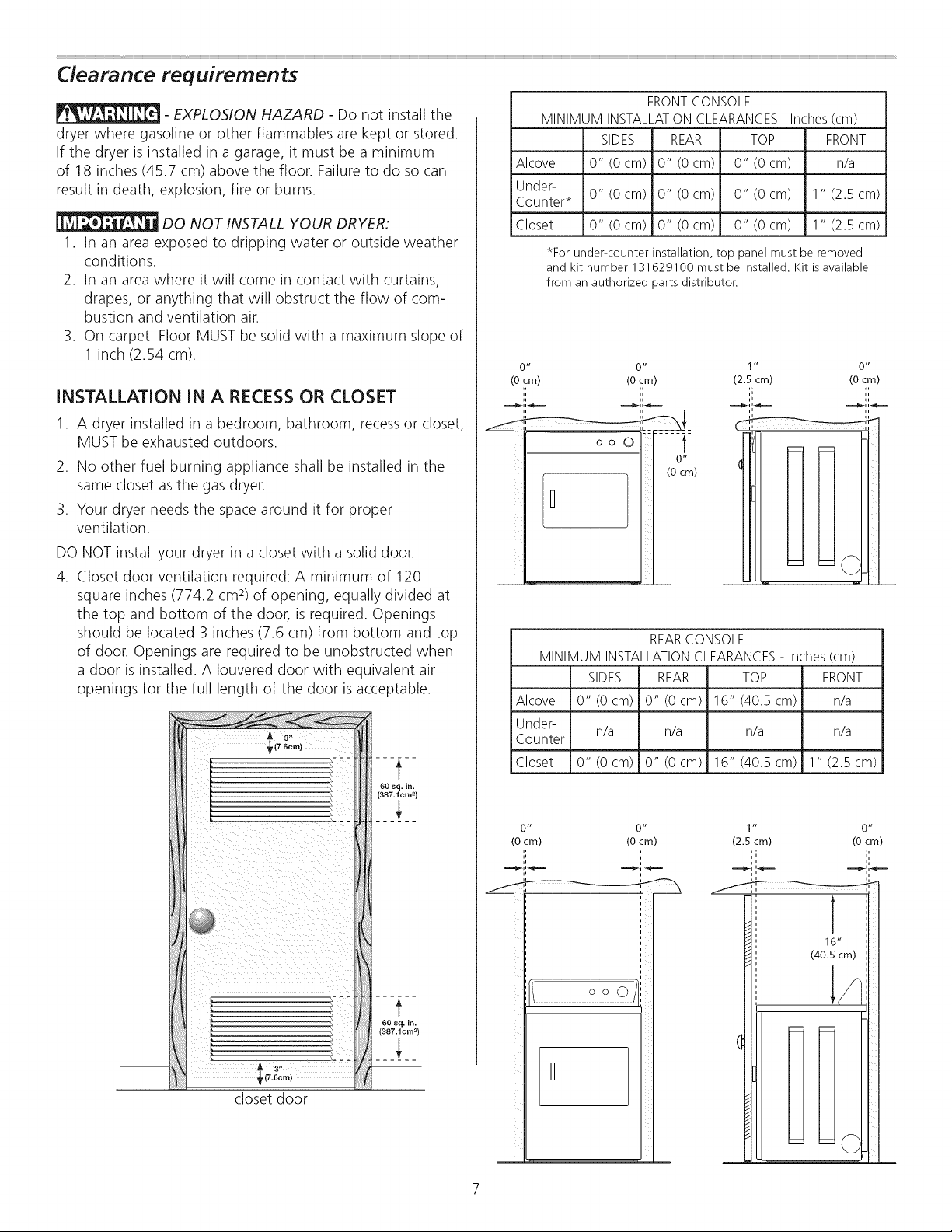
INSTALLATION IN A RECESS OR CLOSET
1. A dryer installed in a bedroom, bathroom, recessor closet,
MUST be exhausted outdoors.
2. No other fuel burning appliance shall be installed in the
same closet as the gas dryer.
3. Your dryer needs the space around it for proper
ventilation.
FRONTCONSOLE
MINIMUMINSTALLATIONCLEARANCES- Inches(cm)
SIDES REAR TOP FRONT
Alcove 0" (0 cm) 0" (0 cm) 0" (0 cm) n/a
Under-
Counter*
Closet 0" (0 cm) 0" (0 cm) 0" (0 cm) 1" (2.5 cm)
0 ,I 0 ,I
(0 cm) (0 cm)
0" (0 cm) 0" (0 cm) 0" (0 cm) 1" (2.5 cm)
*For under-counter installation, top panel must be removed
and kit number 131629100 must be installed. Kit isavailable
from an authorized parts distributor.
1 ii O_l
(2.5 cm) (0 cm)
ooo -ii:
m)
DO NOT install your dryer in a closet with a solid door.
4. Closet door ventilation required: A minimum of 120
square inches (774.2 cm2)of opening, equally divided at
the top and bottom of the door, is required. Openings
should be located 3 inches (7.6 cm) from bottom and top
of door. Openings are required to be unobstructed when
a door is installed. A Iouvered door with equivalent air
openings for the full length of the door is acceptable.
REARCONSOLE
MINIMUM INSTALLATIONCLEARANCES- Inches (cm)
SIDES REAR TOP FRONT
Alcove 0" (0 cm) 0" (0 cm) 16" (40.5 cm) n/a
Under-
Counter
Closet 0" (0 cm) 0" (0 cm) 16" (40.5 cm) 1" (2.5 cm)
0 H
(0 cm)
,,,
n/a n/a n/a n/a
0 ,I
(0 cm)
._.._',',_..,._
1
16"
(40.5 cm)
o o O
closet door
= =©
Page 8
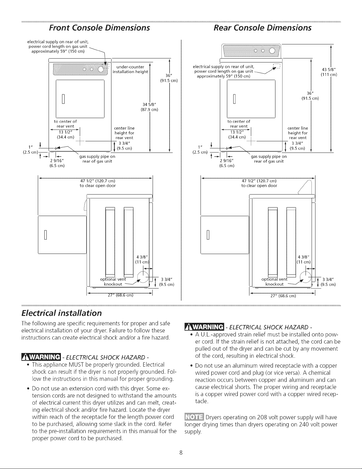
Front Console Dimensions Rear Console Dimensions
electrical supply on rear of unit,
power cord length on gas unit
approximately 59" (150 cm)
1" L
(2.5 cm)_
under-counter l
installation height [
to center of
rear vent center line
13 1/2" _" height for
(34.4 cm) rear vent
--4_t_-"-_ (9.5 cm)
I I
I b- gas supply pipe on
9/16" rear of gas unit
(6.5 cm)
47 112" (120.7 cm)
to clear open door
i 3 3/4"
m m
34 5/8"
(87.9 cm)
T
36"
(91.5 cm)
electrical supply on rear of unit, ,__-_-j
power cord length on gas unit -_
approximately 59" (150 cm)
to center of
rear vent
_" 13 1/2"
(34.4 cm)
1"
(2.5 cm)
_T_ \gas supply pipe on
2 9/16"
(6.5 cm)
rear of gas unit
47 1/2" (120.7 cm)
to clear open door
m
m
center line
height for
rear vent
l 3 3/4"
(9.5 cm)
m
43 5/8"
(111 cm)
4 3/8"
(11 cm)
opt io_-a I yen
knockout _ ----
27" (68.6 cm)
3 3/4"
(9.5 cm)
Electrical installation
The following are specific requirements for proper and safe
electrical installation of your dryer. Failure to follow these
instructions can create electrical shock and/or a fire hazard.
- ELECTRICAL SHOCK HAZARD -
, This appliance MUST be properly grounded. Electrical
shock can result if the dryer is not properly grounded. Fol-
low the instructions in this manual for proper grounding.
• Do not use an extension cord with this dryer. Some ex-
tension cords are not designed to withstand the amounts
of electrical current this dryer utilizes and can melt, creat-
ing electrical shock and/or fire hazard. Locate the dryer
within reach of the receptacle for the length power cord
to be purchased, allowing some slack in the cord. Refer
to the pre-installation requirements in this manual for the
proper power cord to be purchased.
4 3/8"
(11 cm)
opti_l vent
knockout _ --
27" (68.6 cm) _ I
3 3/4"
(9.5 cm)
- ELECTRICAL SHOCK HAZARD -
• A U.L.-approved strain relief must be installed onto pow-
er cord. If the strain relief is not attached, the cord can be
pulled out of the dryer and can be cut by any movement
of the cord, resulting in electrical shock.
• Do not use an aluminum wired receptacle with a copper
wired power cord and plug (or vice versa). A chemical
reaction occurs between copper and aluminum and can
cause electrical shorts. The proper wiring and receptacle
is a copper wired power cord with a copper wired recep-
tacle.
Dryers operating on 208 volt power supply will have
longer drying times than dryers operating on 240 volt power
supply.
Page 9

Grounding requirements - Electric dryer (USA)
- ELECTRICAL SHOCK HAZARD - Improper
connection of the equipment grounding conductor can result
in a risk of electrical shock. Check with a licensed electrician
if you are in doubt as to whether the appliance is properly
grounded.
For a grounded, cord-connected dryer:
1. The dryer MUST be grounded. In the event of a
malfunction or breakdown, grounding will reduce the
risk of electrical shock by a path of least resistance for
electrical current.
2. After you purchase and install a 3 wire or 4 wire power
the plug MUST be plugged into an appropriate, copper
wired receptacle that is properly installed and grounded
in accordance with all local codes and ordinances. If in
doubt, call a licensed electrician.
DO NOT modify the plug you've installed on this appliance.
For a permanently connected dryer:
1. The dryer MUST be connected to a grounded metal,
permanent wiring system; or an equipment grounding
conductor must be run with the circuit conductors and
connected to the equipment-grounding terminal or lead
on the appliance.
supply cord having an equipment-grounding conductor
and a grounding plug that matches you wiring system,
Grounding requirements - Electric dryer (Canada)
- ELECTRICAL SHOCK HAZARD - Improper
connection of the equipment grounding conductor can result
in a risk of electrical shock. Check with a licensed electrician
if you are in doubt as to whether the appliance is properly
grounded.
For a grounded, cord-connected dryer:
1. The dryer MUST be grounded. In the event of a
malfunction or breakdown, grounding will reduce the
risk of electrical shock by a path of least resistance for
electrical current.
2. Since your dryer is equipped with a power supply
cord having an equipment-grounding conductor and
a grounding plug, the plug must be plugged into an
appropriate outlet that isproperly installed and grounded
in accordance with all local codes and ordinances. If in
doubt, call a licensed electrician.
DO NOT modify the plug provided with the appliance.
1. The dryer is equipped with a three-prong (grounding) plug for your
protection against shock hazard and should be plugged directly into a
properly grounded three-prong receptacle.
2. The plug must be plugged into an appropriate outlet that is properly
installed and grounded in accordance with all local codes and ordinances.
If in doubt, call a licensed electrician.
DO NOT cut or remove ground prong from the plug.
Grounding type
wall receptacle
/
Do not, under
any circumstances,
cut, remove,
or bypassthe
grounding prong.
Powercord with
3-prong grounded plug
Page 10

Gas connection
1. Remove the shipping cap from gas pipe at the rear of the
dryer.
DO NOT connect the dryer to L.R gas service
without converting the gas valve. An L.R conversion kit must
be installed by a qualified gas technician.
,
Connect a 1/2 inch (1.27 cm) I.D. semi-rigid or approved
pipe from gas supply line to the 3/8 inch (0.96 cm) pipe
located on the back of the dryer. Use a 1/2 inch to 3/8
inch (1.27 cm to 0.96 cm) reducer for the connection.
Apply an approved thread sealer that is resistant to the
corrosive action of liquefied gases on all pipe connections.
Manual GASFLOW
Shutoff Flare _ Flare
Valve Union Union
; 1 1
:losed t t
k._ Nipple Flexible Inlet Pipeon
Open Connector Back of Dryer
All connections must be wrench-tightened
The supply line must be equipped with an ap-
proved manual shutoff valve. This valve should be located in
the same room asthe dryer and should be in a location that
allows easeof opening and closing. Do not block accessto
the gas shutoff valve.
3. Open the shutoff valve in the gas supply line to allow gas
to flow through the pipe. Wait a few minutes for gas to
move through the gas line.
Shutoff Valve-
Open position
4. Check for gas system leaks with a manometer. If a
manometer is not available, test all connections by
brushing on a soapy water solution.
- EXPLOSION HAZARD - NEVERtest for gas
leaks with an open flame.
Electrical connection (non-Canada) 3-wire cord
- ELECTRICAL SHOCK HAZARD - Failure
to disconnect power source before servicing could result in
personal injury or even death.
1. Turn off power supply to outlet.
2. Remove the screw securing the terminal block access cover in the
upper corner on the back of the dryer.
3. Install a UL-approved strain relief according to the power cord/
strain relief manufacturer's instructions in the power cord entry
hole below the access panel. At this time, the strain relief should
be loosely in place.
4. Thread an UNPLUGGED,UL-approved, 30 amp. power cord,
NEMA 10-30 type SRDT,through the strain relief.
5. Attach the power cord neutral (center wire) conductor to the
SILVERcolored center terminal on the terminal block. Tighten the
screw securely.
6. Attach the remaining two power cord outer conductors to the
outer, BRASScolored terminals on the terminal block. Tighten
both screws securely.
- ELECTRICAL SHOCK HAZARD - Do not
make a sharp bend or crimp wiring/conductor at connections.
3-wire
receptacle
(NEMA type
10-30R)
Neutral
J terminal
DO NOT remove
internal ground in a
3-wire system}
7. Follow manufacturer's guidelines for firmly securing the strain
relief and power cord.
8. Reinstall the terminal block cover.
10
If moving dryer from a 4-wire system
and installing it in a 3-wire system, move the internal
ground from the center terminal back to the GREEN
screw next to the terminal block.
Page 11

Electrical connection (non-Canada) 4-wire cord
- ELECTRICAL SHOCK HAZARD - Failure
to disconnect power source before servicing could result in
personal injury or even death.
1. Turn off power supply to outlet.
2. Remove the screw securing the terminal block access cover in
the upper corner on the back of the dryer.
3. Install a UL-approved strain relief according to the power cord/
strain relief manufacturer's instructionsin the power cord entry
hole below the access panel. At this time, the strain relief should
be loosely in place.
4. Thread an UNPLUGGED,UL-approved, 30 amp. power cord,
NEMA 14-30 type STor SRDT,through the strain relief.
5. Disconnect the internal (WHITE)dryer harness ground wire from
the (GREEN)ground screw next to the terminal block.
6. Attach the ground (GREEN)power cord wire to the cabinet with
the ground (GREEN)screw.Tighten the screw securely.
7. Move the internal dryer harness ground (WHITE)wire to the
terminal block and attach it along with the neutral (WHITE)power
cord wire conductor to the center, SILVERcolored terminal on the
terminal block. Tighten the screw securely.
8. Attach the REDand BLACK power cord conductors to the outer,
BRASScolored terminals on the terminal block. Tighten both
screws securely.
- ELECTRICAL SHOCK HAZARD - Do not
make a sharp bend or crimp wiring/conductor at connections.
9. Follow manufacturer's guidelines for firmly securing the strain
relief and power cord.
10.Reinstall the terminal block cover.
4-wire
receptacle
(NEMA type
14-30R)
GREEN
ground screw
Move internal
ground (WHITE)
wire to neutral
(silver) terminal
for 4-wire system
GREEN
--Neutral
{WHITE wire)
Neutral
WHITE
neutral wire
\
BLACK
or RED
power wire
BLACK
or RED
power wire
General installation
1. Connect the exhaust duct to the outside exhaust system (see
pages 4 through 6). Use of a 4" (10.2 cm) clamp (item A) is
recommended to connect the dryer to the exhaust vent system.
Use metal foil tape to seal all other joints.
2. Carefully slide the dryer to its final position. Adjust one or more of
the legs until the dryer is resting solidly on all four legs. Placea level
on top of the dryer. The dryer MUST be level and resting solidly on
all four legs. Rock alternating corners to check for stability. Remove
and discard door tape.
Be sure the power is off at a circuit breaker/
fuse box before plugging the power cord into an outlet.
3. Plug the power cord into a grounded outlet.
4. Turn on the power at the circuit breaker/fuse box.
5. Read the Use & Care Guide provided with the dryer. It contains ...........
valuable and helpful information that will saveyou time and
money.
6. If you have any questions during initial operation, please review
the "Avoid Service Checklist" in your Use & Care Guide before
calling for service.
7. Place these instructions in a location near the dryer for future
reference.
0
_ _ A
wiring diagram and technical data sheet are
located inside the dryer console.
11
Page 12

Door Reversal Accessories
Your dryer is designed so the door swing may be reversed at
any time without additional parts. Conversion isaccomplished
by transferring hinges to the opposite side of the cabinet.
To change the direction of the door opening:
1. Open the dryer door. Removethe four hinge hole plugs from
the left side of the door opening. Place nearby for future
installation.
You may need a plastic knife to help pull out the
plugs. Be careful not to scratch the paint.
2. Remove the four screws that secure the door hinges to the
dryer front panel (see below).
Failureto use accessories manufactured by (or
approved by) the manufacturer could result in personal injury,
property damage or damage to the dryer.
LP CONVERSION KIT
P/NPCK2003
Gas dryers intended for use in a location supplied with LP
must use a conversion kit prior to installation.
MOBILE HOME INSTALLATION KIT
P/N137067200
Installations in mobile homes require use of MOBILE HOME
INSTALLATIONKIT.
DRYING RACK
Depending on the model you purchased, a drying rack may
have been included in the initial purchase of your dryer.
If your model did not include a drying rack or you desire
another drying rack, you may order one from your local parts
distributor.
DIRECTIONAL VENTING KIT
P/N131456800
Order this kit to utilize the side venting option of the dryer.
Additional hardware available from your local hardware store
will be necessary.
3. Rotate the door 180° and reinstall the door hinges to the
dryer front panel with the four screws.
4. Install the four hinge hole plugs in the open screw holes on
the opposite side of the door opening.
Replacement parts:
If replacements parts are needed for your dryer, contact the
source where you purchased your dryer.
- ELECTRICAL SHOCK HAZARD - Label all
wires prior to disconnection when servicing controls. Wiring
errors can cause improper and dangerous operation. Verify
proper operation after servicing.
TOUCH UP PAINT PENS
White TouchUpPen- P/N5303321319
BisqueTouchUp Bottle - P/N5304414035
BlackTouchUp Pen- P/N5304458932
UNDER-COUNTER INSTALLATION KIT
(front console model only)
For under-counter installation, top panel must be removed
and kit number 131629100 must be installed.
DRYER STACKING KIT
(front console model only)
P/N5303937141
Depending on the model you purchased, a kit for stacking
this dryer on top of matching washer may have been
included in the initial purchase of your dryer. If your model
did not include a stacking kit or you desire another stacking
kit, you may order one.
15 INCH (38 cm) PEDESTAL
(front console model only)
A pedestal accessory,specifically designed for this dryer may
be used to elevate the dryer for ease of use. This pedestal will
add about 15" (38 cm) to the height of your unit for a total
height of 51.25" (130 cm). Contact the location where you
purchased your dryer.
12
Page 13

lndice
instrucciones importantes de seguridad ............................... 13
Requisitos de preinstalacion ................................................ 13
Requisitos de instalaci0n ............................................... 14-18
Dimensiones de la lavadora instalada .................................. 19
instrucciones de instalaci0n ........................................... 19-22
inversion de la puerta .......................................................... 23
Accesorios/Piezas de repuesto ............................................. 23
lnstrucciones importantes de seguridad
Parasu seguridad, debe seguir la informacion de esta guia para minimizar el riesgo de incendio o
explosion o para evitar dahos a la propiedad, lesiones personales o incluso la muerte. No almacene ni utilice gasolina ni otros
liquidos o vapores inflamables cerca de este o de cualquier otro electrodomestico.
Identificaci6n de los simbolos, palabras y avisos de seguridad
Lasindicaciones de seguridad incluidas en este manual aparecen precedidas de un aviso titulado "ADVERTENCIA" o "PRE-
CAUCION", de acuerdo con el nivel de riesgo.
_Este simbolo le advierte sobre situaciones que pueden causar lesiones personales graves, la muerte o
dahos materiales.
_Este simbolo le advierte sobre situaciones que pueden causar lesiones personales o dahos materiales.
Lea las siguientes instrucdones antes de instalar y utilizar este electrodom6stico:
o Despuesde desembalar la secadora, destruya los cartones y lasbolsas de pl_istico. Los nihos podr[an utilizarlos para jugar. Los
cartones cubiertos con alfombras, cubrecamas, o I_iminasde pl_istico pueden convertirse en c_imarasde aire hermeticamente
cerradas y provocar asfixia. Coloque todos los materiales en un basurero o mantengalos fuera del alcance de los nihos.
La instalaci0n y el servicio de la secadora de ropa deben ser Ilevados a cabo por un instalador calificado, agencia de servi-
cios o proveedor de gas.
Instale la secadora de ropa de acuerdo con las instrucciones del fabricante y los codigos locales.
La reparacion eDctrica de la secadora debe cumplir con los codigos y lasordenanzas locales y la 01tima edici0n del Codigo
Electrico Nacional (National Electrical Code), el ANSI/NFPA70, o bien en Canada, el CSA C22.1 del Codigo Electrico de
Canada (Canadian Electrical Code) Parte 1.
El servicio de gas de la secadora debe cumplir con los codigos y las ordenanzas locales, y la ultima edicion del Codigo de
Gas Nacional (National Fuel GasCode), el ANSi Z223.1, o bien en Canada1,el CAN/CGA B149,1-2000.
La secadora se diseh6 conforme a los codigos ANSi Z 21.5.1 o ANSI/UL 2158 - CAN/CSA C22.2 N.° 112 (ultimas edicio-
nes) solo para USO DOMESTICO. No se recomienda esta secadora para uso comercial, como por ejemplo, en restaurantes,
salones de belleza, etc.
Lasinstrucciones de esta guia y todo el material que se incluye con esta secadora no tienen como prop6sito cubrir todas
las condiciones y situaciones que puedan presentarse. Cuando instale, opere o repare cualquier artefacto DEBEtener cui-
dado y hacer uso de buenas pr_icticas de seguridad.
QUI _ HACER SI SIENTE OLOR A GAS:
No intente encender ning0n electrodomestico.
No toque ningun interruptor electrico; no utilice ningun telefono en la vivienda.
Despeje la habitacion, el edificio o el _ireade todos los ocupantes.
Llame inmediatamente a su proveedor de gas desde el telefono de un vecino. Siga las instrucciones del proveedor de gas.
Si no puede ponerse en contacto con el proveedor de gas, Ilame a los bomberos.
Conserve estas instrucciones para referencia futura.
Requisitos de preinstalaci6n
Herramientas y materiales necesarios para la instalaci6n:
Pinzas ajustables
Destornilladores Philips con punta
derecha y cuadrada
Llave ajustable
Llave para tubos de suministro de gas
Cinta aislante resistente al gas LP
(para suministro de gas natural o LP)
Nivel de carpintero
Capucha de ventilacion externa
Conducto de escape de metal rigido
o semirigido de 4 pulgadas (10 cm)
Kit de cablesde alimentaci6ntrifilar o te-
trafilar de 240 voltios (secadoraelectrica)
Abrazadera de 4" (10,2 cm)
V_ilvulade cierre de linea de gas (se-
cadora a gas)
Adaptadores NPIde union acampana-
da (x2) y linea flexible de suministro de
gas (secadora a gas) de 1/2'(15,2 cm)
Cinta de papel aluminio (no cinta
adhesiva aislante)
13
Page 14

Requisitos de! sistema electrico
_: Debido a posibles variaciones en el voltaje, no se recomienda utilizar esta secadora con electricidad generada a
partir de generadores a gas, solares, eolicos ni de ninguna otra clase que no sean los empleados pot su empresa de electri-
cidad local.
Requisitos electricos de la secadora electrica:
CIRCUITO: circuito independiente individual de 30 amp. con fusibles de acci0n retardada o disyuntores. Use circuitos con
fusibles separados para la lavadora y la secadora. NO haga funcionar una lavadora y una secadora en el mismo circuito.
SUMINISTROELECTRICO:trifilar o tetrafilar, 240 V, 1 fase, 60 Hz, corriente alterna.
A menos que hayasido fabricada para la venta en Canada1,estasecadoraest,1conectadaa tierra internamente a
travesde un enlace a un conductor neutro. Laconexi0n a tierra a travesde{ neutro est,1prohibida para: (1) instalacionesde circuitos de
bifurcaci0n nuevos;(2) casasrodantes; (3)vehiculosrecreativos;y (4)_ireascuyas leyeslocalesno permiten la puesta a tierra a travesdel
neutro.
RECEPTACULODELTOMACORRIENTE- recept_iculo NEMA 10-30 R o NEMA 14-30 Rque debe estar ubicado en un lugar al
que pueda acceder el cable de alimentaci0n electrica cuando la secadora este instalada.
CONEXION A TIERRA:consulte "Requisitos de conexi0n atierra" en la secci0n {nstalaci0n electrica.
CABLE DE ALIMENTACION ELECTRICATRIFILAR (no
incluido)
Receptaculo trifilar
(tipo NEMA 10-30R)
La secadora DEBEemplear un cable de alimentaci0n
electrica de 3 conductores tipo NEMA 10-30, SRDT
calificado para CA minima de 240 voltios, 30 amp., con 3
conectores de terminal horquilla con extremos doblados
hacia arriba o de bucle cerrado y calificados para uso en
secadoras de ropa. Paraobtener instrucciones sobre {a
conexi0n trifilar, consulte CONEXIONESELECTRICASPARA
UN SISTEMATRIFILAR.
Requisitos electricos de la secadora a gas:
CIRCUITO- Circuito individual de bifurcaci0n de 15 amp.,
correctamente polarizado y con conexi0n a tierra con fusible
de retardo de 15 amp. o con interruptor autom_itico.
SUMINISTROELECTRICO:corriente alterna de 2 cables, con
conexi0n a tierra, 120 voltios, monof_isica, 60 Hz.
CABLEDE ALIMENTACION ELECTRICA:la secadora est,1
equipada con un cable de alimentaci0n trifilar de 120 voltios.
CONEXION A TIERRA:consulte "Requisitos de conexi0n atierra"
en la secci0n Instalaci0n electrica.
CABLE DE ALIMENTAClON ELECTRICATETRAFILAR (no
incluido)
Receptaculo tetrafilar
(tipo NEMA 14-30R)
La secadora DEBEemplear un cable de alimentacion
electrica de 4 conductores tipo NEMA 14-30, SRDTo
ST(segun se especifique) calificado para CA minima
de 240 voltios, 30 amp., con 4 conectores de terminal
horquilla con extremos doblados hacia arriba o de bucle
cerrado y calificados para uso en secadoras de ropa.
Para obtener instrucciones sobre {aconexi0n tetrafilar,
consulte CONEXIONESELECTRICASPARA UN SISTEMA
TETRAFILAR.
_ Lassecadoras fabricadas para la venta en Canada1vie-
nen con un cable de alimentaci0n electrica tetrafilar (NEMA
14-30R) de flibrica.
Tomacorriente con
retire ni "q
deshabilite la clavija de
conexi6n a tierra bajo
Cord6n el_t-trico de 3 clavijas
con puesta atiema
14
Page 15

Requerimientos del suministro de gas
- PELIGRO DE EXPLOSION - Las tube- 4.
rias de cobre sin recubrimiento se corroen al exponerse al gas
natural, Io que provoca perdiclas de gas. Utilice SOLAMENTE 5.
tuberias de hierro negro, acero inoxiclable o lat6n plastificaclo
para el suministro de gas.
1. Lainstalaci6n DEBErealizarsede acuerdo con los c6digos
localeso, en ausencia de ellos, con el C6cligo de Gas
Nacional (National FuelGas Code), ANSIZ223.1 (Oltima 6.
edici6n).
2. La linea de suministro de gas clebe ser un tubo de 1,27 cm
(1/2 pulgada). 7.
3. Si los c6digos Io permiten, se puecle utilizar un tubo de
metal flexible para conectar la secaclora a la linea de
suministro de gas. Latuberia DEBEser de acero inoxiclable 8.
o de lat6n plastificaclo.
Requisitos del sistema de escape
Utilice solo un conducto de metal flexible o rigido de 10,2
cm (4 pulgadas) de diametro (minimo) y una capucha de
ventilaci0n aprobada que tenga uno o mas reguladores de
tiro que se abran cuando la secadora este en funcionamiento.
Cuando la secadora se detiene, el regulador de tiro se
cierra automaticamente para evitar la corriente de aire y el
ingreso de insectos y roeclores. Para evitar restringir la salida
clel conducto, mantenga un espacio minimo de 30,5 cm
(12 pulgadas) entre la capucha de ventilaci0n y el suelo, o
cualquier otra obstrucci0n.
La linea de suministro de gas DEBEtener una valvula de
cierre individual.
Se DEBEinstalar una clerivaci0n N.RT de 0,32 cm (1/8
pulgadas) con tap0n roscaclo, que permita conectar
un meclidor de prueba, inmecliatamente clespuesde
la conexi0n de suministro de gas a la secadora, en
contracorriente al flujo de gas.
La secadora DEBEestar clesconectada de la tuberia de gas
durante cualquier prueba en la que la presi0n excecla los
3,45 kPa (1/2 psig).
La secadora DEBEestar aislaclade la tuberia de gas
clurante cualquier prueba en la que la presi0n sea igual o
inferior a 3,45 kPa (1/2 psig).
Lasconexiones clelsuministro de gas cleben cumplir con
la norma de conexiones de electrodomesticos a gas, ANSi
Z21.24.
- PELIGRO DE INCENDIO - El no
seguir estas instrucciones puecle producir tiempos de secado
excesivos y peligro de incendio.
Los siguientes son requisitos necesarios para el
funcionamiento seguro y correcto de su secadora.
- PELIGRO DE INCENDIO - No utilice
materiales de ventilaci0n de plastico ni de papel de aluminio
flexibles para instalar la secaclora de ropa. Por Io general,
dichos materiales se clesarman, se deterioran con facilidad y
acumulan pelusa. Estasconcliciones obstruyen el flujo de aire
de la secadora y aumentan el riesgo de incendio.
Si su sistema actual est,1compuesto de un conclucto de
pl_istico o papel de aluminio, reempl_icelo por un conclucto
de metal rigiclo o semirigiclo. Aseg0rese de que el conclucto
existente no tenga pelusas antes de instalar el conclucto de la
secaclora.
Correcto Incorrecto
15
Page 16

Requisitos del sistema de escape (continuaci6n)
- PELIGRO DE INCENDIO - Una seca-
dora de ropa debe tenet ventilaci0n a{ exterior. No ventile {a
secadora a una chimenea, pared, techo, _itico, pasajes entre
pisos ni ning0n espacio oculto de {avivienda. Lassecadoras
de ropa producen pelusa combustible. Si {asecadora no tiene
ventilaci0n a{ exterior, algunas pelusas finas se expulsar_in en
el _ireade lavanderia. La acumulaci0n de pelusa en cualquier
_ireade la vivienda puede constituir un peligro sanitario y un
riesgo de incendio.
La secadora debe estar conectada a un sistema de escape que
termine en el exterior de {avivienda. Inspeccione la abertura
de escape a{ exterior con frecuencia y elimine cualquier
acumulaci0n de pelusa en la abertura y en el _ireaque la
rodea.
- PELIGRO DE INCENDIO -
• No permita que materiales combustibles (pot ejemp{o:
ropa, tapiceria/cortinas, pape{) entrenen contacto con
el sistema de escape. La secadora NO DEBEtenet escape
a una chimenea, una pared, un techo ni ningun espacio
cerrado de un edificio que pueda acumular pelusa y cons-
tituir un peligro de incendio.
No bloquee los extremos de escape de{ sistema de ven-
tilaci0n, ni utilice tornillos, remaches ni otros sujetadores
que se extiendan hacia {a parte interna de{ conducto para
ensamblar{o. Es posible que {a pelusa quede atrapada en
el filtro, los tornillos o los remaches, Io que puede obstruir
la red de conductos y constituir un peligro de incendio,
asi como tambien aumentar los tiempos de secado. En {a
salida de{ conducto a{exterior, utilice una capucha de ven-
tilaci0n aprobada y selle todas {asuniones con cinta para
conductos. Todos los accesorios macho para tubos DEBEN
instalarse teniendo en cuenta el flujo de aire.
- PELIGRO DE INCENDIO - Si se exce-
de la Iongitud del tubo del conducto o el n0mero de codos
permitidos en las tabias de "LONGITUD MAXIMA", se pue-
den acumular pelusas en el sistema de escape. La obstrucci0n
del sistema podria constituir un peligro de incendio, asi como
aumentar los tiempos de secado.
¢h
Conducto de metal r[gido de 10,2 cm (4 pulgadas)
e_
t_
D_
°o 4" aberturas de
0 18.3 m (60 pies) 14.6 m (48 pies)
1 15.9 m (52 pies) 12.2 m (40 pies)
2 13.5 m (44 pies) 9.8 m (32 pies)
3 9.8 m (32 pies) 7.3 m (24 pies)
4 9.5 m (28 pies) 4.9 m (16 pies)
(recomendada)
(10,2 cm) ventilacibn
LONGITUD MAXIMA
TIPO DECAPUCHA DEVENTILACION
2.5"
(6,35 cm)
- PELIGRO DE INCENDIO -
No utilice material de ventilacion flexible de pbistico o
aluminio.
Siva a instalar conductos de ventilaci0n semirrigidos, no
exceda una Iongitud de 8 pies (2,4 m).
Instale los accesorios macho en la direction
correcta:
16
CORRECTO INCORRECTO
Page 17

Requisitos de/sistema de venti/acion (continuacion)
En instalaciones en lasque el sistema de ventilacion no se
describa en las tablas, sedebe utilizar el siguiente metodo
para determinar si dicho sistema esaceptable:
1. Conecte un manOmetro inclinado o digital entre la secadora
y el punto donde el tubo de ventilacion se conecta con la
secadora.
,
Coloque el temporizador y la temperatura de la secadora
en la opcion Air fluff - cool down (Esponjado con aire,
enfriamiento) y ponga en marcha la secadora.
,
Lea la meclicion del manometro.
4.
La contrapresion del sistema NO DEBEset mayor que 2,5
cm (1 pulgada) de columna de agua. Si la contrapresion
del sistema esmenor que 2,5 cm (1 pulgada) de
columna de agua, el sistema es aceptable. Si la lectura
del manometro es mayor que 2,5 cm (1 pulgada) de
columna de agua, el sistema es demasiado restrictivo y la
instalacion es inaceptable.
Si bien la orientacion vertical del sistema de ventilacion es
aceptable, ciertas circunstancias atenuantes podrian afectar el
funcionamiento de la secadora:
o
Solo sedebe utilizar una red de conductos de metal rigido.
o
Si la ventilacion se efectua en forma vertical a traves del
techo, es posible que el sistema de ventilacion se vea
expuesto a r_ifagasdescendentes que restringir_in la
ventilacion.
• Si el sistema de escape se extiende a traves de un _irea
que no est,1aislada, puecle producirse condensacion y una
acumulacion m_isr_ipida de pelusa.
• La compresion o los pliegues del sistema de ventilacion
aumentar_in la restriccion de la ventilacion.
Se debe inspeccionar y limpiar el sistema de ventilacion
cada 18 meses como minimo cuando se le da un uso
normal. Cuanto m_isutilice la secadora, m_isa menudo
deber_i comprobar que el sistema de escape y la capucha
de ventilacion funcionan correctamente.
DirecciOn del Venti/aciOn
Toclaslas secadoras vienen de flibrica equipadas con
ventilacion trasero. Sin embargo, en las secadoras electricas,
el ventilacion puede hacerse al lado derecho o izquierdo
del gabinete o en la parte inferior de la secadora. En las
secadoras a gas, el ventilacion del aire puecle estar en el lado
derecho del gabinete o en la parte inferior de la secadora. El
ventilacion direccional puede efectuarse instalando un Kit de
Ventilacion Direccional, P/N 131456800, disponible a traves
de su distribuidor de repuestos. Siga las instrucciones que se
suministran con el kit.
__ii!___-_ _ _
[/
13 1/2"
4 3/8"
11 cm)
3 3/4"
(9.5 cm
\
3 3/4"
(34 cm)
(9.5 cm)
Instalacion en una casa rodante
1. La instalacion DEBEcumplir con la actual Norma de
Seguridad y Construccion de Casas Rodantes, titulo 24
CFR, Parte 32-80 (que anteriormente se conocia como
la Norma Federal de Seguridad y Construccion de Casas
Rodantes [Federal Standard for Mobile Home Construction
and Safety], titulo 24, HUD parte 280) o la Norma CAN/
CSAZ240 MH.
2. La secadora DEBEtenet evacuacion al exterior (no a la
parte de abajo de la casa rodante) mediante conductos
met_ilicos que no admitan combustion. Los conductos
met_ilicos deben tenet un di_imetro de 10,16 cm (4
pulgadas) y no deben presentar obstrucciones. Se
recomiendan los conductos de metal rigido.
3. Si la secadora tiene evacuacion a traves del piso, y el
_ireadebajo de la casa rodante es cerrada, el sistema de
evacuacion DEBEterminar fuera del espacio cerrado y el
extremo debe quedar sujetado firmemente a la estructura
de la casa rodante.
4. Para obtener informacion sobre otros requisitos
importantes del sistema de escape, consulte lassecciones
anteriores de esta guia.
5. Cuando se instale una secadora a gas en una casa
rodante, se debe dejar espacio en el exterior para la salida
de aire. Este espacio debe set pot Io menos el doble del
_ireade la salida de escape de la secadora.
6. Eltecnico de instalacion DEBEanclar esta secadora (1)
o secadora sobre pedestal (2) al piso usando un kit de
instalacion para casas rodantes, pieza numero 137067200.
17
Page 18

Requisitos de despeje
- PELIGRO DE EXPLOSION - No insta-
le la secadora en el mismo lugar en el que haya o sealma-
cene gasolina u otros productos inflamables. Si la secaclora
se instala en un garaje, debe estar a una altura minima de
45,7 cm (18 pulgadas) por encima del suelo. De Io contrario,
podria producirse una explosion, un incenclio, quemacluras o
incluso la muerte.
NO INSTALE LA SECADORA:
1. En una zona expuesta a la humedacl o a las concliciones
climaticas externas.
2. En un _ireaen la que este en contacto con cortinas, telas
colgantes o cualquier otra cosa que pueda obstruir el
flujo de aire de ventilacion y combustion.
3. Sobre una alfombra. El piso DEBEser firme con una pen-
diente maxima de 2,54 cm (1 pulgada).
INSTALAClON EN UN NICHO O ARMARIO
1. Una secadora instalada en un dormitorio, baflo, nicho o
armario, DEBEtenet ventilacion al exterior.
2. No sedebe instalar ningun otto artefacto de combustion
en el mismo armario que la secadora a gas.
3. La secadora necesita espacio a su alrededor para que la
ventilacion sea adecuada.
CONSOLAFRONTAL
ESPAClOSM{NIMOSPARALAINSTALACION:cm(pulgadas)
LATERALES
Hueco 0 cm (0") 0 cm (0") 0 cm (0") n/d
Empotrada* 0 cm (0") 0 cm (0") 0 cm (0") 2,54 cm (1 ")
Armario 0 cm (0") 0 cm (0") 0 cm (0") 2,54 cm (1")
*Para instalaci6n empotrada, el panel superior debe ser removido y
el kit 131629100 debe ser instalado. El kit puede ser ordenado de su
distribuidor autorizado.
O" O"
(0 cm) (0 cm)
PARTE PARTE PARTE
TRASERA SUPERIOR DELANTERA
1" O"
(2.5 cm) (0 cm)
ooo --ii:
m)
NO instale la secadora en un armario con puerta maciza.
4. Ventilacion requerida en la puerta del armario: Se necesita
un minimo de 774,2 cm2 (120 pulgadas 2)de abertura,
dividido en partes iguales en la parte superior e inferior
de la puerta. Lasaberturas de ventilacion deben estar
ubicadas a 7,6 cm (3 pulgadas) de la parte superior e
inferior de la puerta. Esnecesario que las aberturas de
aire no esten obstruidas al instalar una puerta. Se acepta
una puerta que tenga aberturas de ventilacion distribuidas
uniformemente en toda la superficie.
i 3'(7.6cm}
i ____
CONSOLATRASERA
ESPAClOSM{NIMOSPARALA INSTALACl0N:cm (pulgadas)
LATERALES PARTESUPERIOR
Hueco 0 cm (0") 0 cm (0") 40.5 cm (16") n/d
Empotrada n/d n/d n/d n/d
Armario Ocm(O") Ocm(O") 40.5 cm (16") 2,54 cm (1")
0"
(0 cm)
,,,
ii
ii
PARTE PARTE
TRASERA DELANTERA
0"
(0 cm)
_._',',_..,._
1
16"
(40.5 cm)
o o O
puerta del armario
= =©
18
Page 19

Dimensiones Consola Frontal Dimensiones Consola Trasera
suministro electrico en la parte trase-
ra de la unidad, cable elOctrico en la
parte trasera de la secadora a
de aproximadamente 59" (150 cm)
under-counter l
T
36"
(91.5 cm)
suministro el_ctrico en la parte trase-
ra
de la unidad, cable el_ctrico en la ,_-_-_
parte trasera de la secadora a gas es _"
de aproximadamente 59" (150 cm)
43 5/8"
(111 cm)
hacia el centro de
la ventilacion t_asera
-_ 13 1/2" _'/
(34.4 cm)
9/16"
(6.5 cm)
/
tuberia de suministro de gas en la
parte trasera de la unidad de gas
47 1/2" (120.7 cm)
para destapar abra la puerta
installation height /
altura de la
linea central
para
ventilaci6n
trasera
i 3 3/4"
(9.5 cm)
m m
34 5/8"
(87.9 cm)
:l 3/8"
11 cm)
hacia el centro de
la ventilaciO_ trasera
_" 13 1/2" _|
(34.4 cm) ]
(2.5 cm) _ \
2 9/16"
(6.5 cm)
47 1/2" (120.7 cm)
para destapar abra la puerta
36 II
(91.5 cm)
altura de la
linea central
para
ventilaci6n
trasera
l 3 3/4"
(9.5 cm)
tuberia de suministro de gas en la
parte trasera de la unidad de gas
m m
m
4 3/8"
(11 cm)
dlscoo c_or ren_vl _'_t_
ble para ventilacidn _/ --
27" (68.6 cm) _'I
3 3/4"
(9.5 cm)
Instalacion electrica
Lossiguientes son requisitos necesariospara la instalacion
electrica segura ycorrecta de su secadora. Elno seguir estas
instrucciones puede producir una descargaelectrica y/o incendio.
- PELIGRODEDESCARGA ELE-CTRICA-
• Esteelectrodomestico DEBEestar debidamente conec-
tado a tierra. Si la secadora no est,1conectada a tierra
correctamente, se pueden producir descargas electricas.
Siga las instrucciones de esta guia para vet como se reali-
za una correcta conexion a tierra.
No utilice un cable de extension con esta secadora.Algu-
nos cablesde extension no estan dise_ados para soportar
la cantidad de corriente electrica que utiliza esta secadoray
pueden derretirse, Io que constituye un peligro de descarga
electricay/o incendio. Ubique la secadoraen un lugar donde
el cable de alimentacion que compre esteal alcancedel re-
ceptaculo, permitiendo que el cable quede holgado. Consul-
te los requisitos de preinstalacion de esta guia para ver cual
esel cable de alimentacion correcto que sedebe comprar.
disco opc_-o-nonalrem-_Tvl-
ble para ventilation _/-"
27" (68.6 cm) _ [
3 3/4"
(9.5 cm)
I
- PELIGRODEDESCARGA ELECTRICA-
• Debe instalarse, en el cable de alimentacion, un disposi-
tivo de liberacion de tension aprobado por U.L. Si no se
coloca un dispositivo de liberacion de tension, el cable
podria desenchufarse de la secadora y cortarse por cual-
quier movimiento, y provocar asi una descarga electrica.
No utilice un recept_iculo con cableado de aluminio para
un enchufe y cable de alimentacion con cables de cobre
(o viceversa). La reaccion quimica que tiene lugar entre el
cobre y el aluminio puede causar cortocircuitos electricos.
El recept_iculo y el cableado correcto consiste en un cable
de alimentacion con alambres de cobre con un recept_i-
culo de cables de cobre.
Lassecadoras que funcionan con 208 voltios de co-
rriente electrica tendr_in tiempos de secado m_isprolongados
que las que funcionan con 240 voltios de corriente electrica.
19
Page 20

Requisitos de conexion a tierra: secadora electrica (Estados Unidos)
- PELIGRODEDESCARGA ELE-CTRICA-
Una conexion incorrecta del conductor de conexion a tierra del
equipo puede provocar un peligro de descargaelectrica. Si no
est,1seguro de haber realizadocorrectamente la conexion a
tierra del artefacto, consulte a un electricista autorizado.
Para una secadora conectada a tierra:
1. La secadora DEBEtenet conexi0n a tierra. En el caso
de que {a secadora no funcione correctamente o se
descomponga, la conexi0n a tierra reduce el riesgo de
descarga electrica porque ofrece una trayectoria de menor
resistencia para {a corriente electrica.
2. Despues de comprar e instalar un cable de alimentaci0n
trifilar o tetrafilar con un conductor de conexi6n a tierra,
adecuado con cable de cobre correctamente instalado y
con conexi0n a tierra, de acuerdo con todos los codigos y
lasordenanzas locales. Ante cualquier duda, comuniquese
con un electricista autorizado.
NO realice modificaciones al enchufe que haya instalado en
este artefacto.
Para una secadora conectada de forma permanente:
1. La secadora DEBEestar conectada a un sistema de
cabieado permanente de metal conectado a tierra, o bien
se debe co{ocar un conductor de conexi0n a tierra con
los conductores del circuito y debe estar conectado al
terminal de conexi0n a tierra de{ equipo o a{ cable a tierra
de{ artefacto.
el enchufe DEBEestar conectado a un recept_icu{o
Requisitos de conexion a tierra: secadora electrica (Canada)
- PELIGRODEDESCARGA ELE-CTRICA-
Una conexion incorrecta del conductor de conexion a tierra del
equipo puede provocar un peligro de descargaelectrica. Si no
est,1seguro de haber realizadocorrectamente la conexion a
tierra del artefacto, consulte a un electricista autorizado.
Para una secadora conectada a tierra:
, La secadora DEBEtenet conexi0n a tierra. En el caso
de que {a secadora no funcione correctamente o se
descomponga, la conexi0n a tierra reduce el riesgo de
descarga electrica porque ofrece una trayectoria de menor
resistencia para la corriente electrica.
2. Debido a que la secadora est,1equipada con un cable de
alimentaci0n electrica que cuenta con un conductor de
conexi6n a tierra, el enchufe debe estar conectado a un
tomacorriente correctamente instalado y con conexi0n a
tierra, de acuerdo con todos los c6digos y {asordenanzas
locales. Ante cualquier duda, comuniquese con un
electricista autorizado.
NO realice modificaciones al enchufe que se proporciona con
este artefacto.
Requisitos de conexion a tierra: secadora a gas (Estados Unidos y Canada)
,
La secadora est,1equipada con un enchufe de tres patas
(conexi0n a tierra) para evitar el peligro de electrocuci0n
y debe estar conectada directamente a un recept_iculo
de enchufe de tres patas que cuente con una conexi0n a
tierra adecuada.
, El enchufe debe estar conectado a un tomacorriente
correctamente instalado y con conexi0n a tierra, de
acuerdo con todos los c6digos y las ordenanzas locales.
Ante cualquier duda, comuniquese con un electricista
autorizado.
NO corte ni retire la espiga de conexi0n a tierra del enchufe.
Tomacorriente con
puesta a tierra
retire ni
deshabilite la davija de
conexi6n a tierra bajo
n{nguna circunstancia.
Cord6n el_ctrico de 3 davijas
con puesta atierra
20
Page 21

Conexion de gas
1. Quite el tapon del tubo de gas en la parte trasera de la
secadora.
NO conecte la secadora al servicio de gas
LPsin convertir la wilvula de gas. El kit de conversion a gas LP
debe set instalado pot un tecnico calificado.
,
Conecte un tubo aprobado o uno semi-rigido de 1,27
cm (1/2 pulgada) de di_imetro interior desde la linea
de suministro de gas al tubo de 0,96 cm (3/8 pulgada)
ubicado en la parte trasera de la secadora. Utilice un
reductor de 1,27 cm a 0,96 cm (1/2 pulgada a 3/8
pulgada) para realizar la conexi0n. Aplique un sellador
para roscasque sea resistente a la acci0n corrosiva de los
gases licuados en todas lasconexiones de los tubos.
3. Abra la wilvula de cierre de la linea de suministro de
gas para que el gas fluya a traves de la tuberia. Espere
unos minutos a que el gas fluya a traves de la linea de
suministro de gas.
V_ilvula
de cierre Conector Conector
manual doble doble
FLUJO DE GAS
V_ilvula de cierre:
posiciOn abierta
4. Utilice un manometro para verificar que no haya fugas
Conector Tubo de ladmisiOn
flexible en la parte posterior
Todas las conexiones deben estar ajustadas con Ilave
de la secadora
La linea de suministro de gas debe estar
en el suministro de gas. Si no cuenta con un manometro,
pruebe todas lasconexiones aplicando agua jabonosa en
estas.
compruebe si hay fugas de gas con una llama abierta.
equipada con una wilvula de cierre manual aprobada. Esta
wilvula debe estar ubicada en la misma habitaci0n que la se-
cadora, en una ubicaci0n que permita la facilidad de apertura
y cierre. No bloquee el acceso a la wilvula de cierre de gas.
Conexion electrica (fuera de Canada): trifilar
- PELIGRODEDESCARGA ELE-CTRICA-
El no desconectar el suministro electrico antes de realizar cualquier
reparaciOn puede ocasionar lesiones personales o incluso la muerte.
1. Desconecte el suministro electrico del tomacorriente, trifilar
2. Extraigael tornillo que sujeta la cubierta de accesodel bloque terminal (tipo NEMA
que seencuentra en laesquina superiorde la parte traserade la secadora. 10-30R)
3. Instale un dispositivo de liberaci0n de tension aprobado pot U.L.,
de acuerdo con las instrucciones relativas al cable de alimentacion/
dispositivo de liberaci0n de tension del fabricante, en el orificio de
entrada del cable de alimentacion debajo del panel de acceso. En
este momento, el dispositivo de liberaci0n de tension debe estar
holgadamente en su lugar.
4. Paseun cable de alimentacion aprobado pot U.L. DESENCHUFADO,
de 30 amp. tipo NEMA 10-30, SRDTa traves del dispositivo de
liberaci0n de tension.
5. Conecte el conductor neutro (cable del centro) del cable de
alimentacion al terminal PLATEADOdel centro del bloque terminal.
Ajuste el tornillo con firmeza.
6. Conecte los dos conductores externos restantes del cable de
alimentacion a los terminales externos de color LATONdel bloque
terminal. Ajuste los dos tornillos con firmeza.
- PELIGRODE DESCARGA ELE-CTRICA-
No forme un _ingulo agudo con el cableado/conductor, ni los
doble en el punto de conexion.
7. Siga las pautas del fabricante para sujetar firmemente el dispositivo
de liberacion de tension y el cable de alimentacion.
8. Vuelva a instalar la cubierta del bloque terminal.
21
Recept_iculo
iNO retire la conexibn
interna a tierra
en los sistemas trifilares!
sistema tetrafilar e instalarla en un sistema trifilar,
mueva la conexion a tierra interna del terminal
central nuevamente hacia el tornillo VERDEque se
encuentra junto al bloque terminal.
- PELIGRO DE EXPLOSION - NUNCA
Terminal
J neutro
Paramover la secadora desde un
Page 22

Conexion electrica (fuera de Canada): tetrafilar
- PELIGRODE DESCARGAELECTRICA-
El no desconectar el suministro electrico antes de realizar cualquier
reparacion puede ocasionar lesiones personales o incluso la muerte.
1. Desconecte el suministro electrico del tomacorriente.
2. Extraigael tornillo que sujeta lacubierta de accesodel bloque terminal
que seencuentra en la esquinasuperior de la parte traserade la secadora.
3. Instaleun dispositivo de liberacion de tension aprobado por U.L., de
acuerdo con lasinstrucciones relativasal cable de alimentacion/dispositivo
de liberacion de tension del fabricante, en el orificio de entrada del
cable de alimentacion debajo del panel de acceso.Eneste momento, el
dispositivo de liberacion de tension debeestar holgadamente en su lugar.
4. Paseun cable de alimentacion aprobado por U.L. DESENCHUFADO,
de 30 amp. tipo NEMA 14-30, SRDTo STa traves del dispositivo de
liberacion de tension.
5. Desconecte el cable interno (BLANCO)de conexion a tierra que
integra el enchufe preformado de la secadora del tornillo de
conexion a tierra (VERDE)que est,1junto al bloque terminal.
6. Conecte el cable de conexion a tierra (VERDE)del cable de
alimentacion al gabinete utilizando el tomillo (VERDE)de conexion a
tierra. Ajuste el tornillo con firmeza.
7. Muevael cableinterno (BLANCO)de conexionatierra que integra el
enchufe preformado de la secadoraal bloque terminal y conectelojunto
con el conductor neutro(BLANCO)del cablede alimentacional terminal
PLATEADOdel centro del bloque terminal.Ajuste el tornillo confirmeza.
8. Conecte los conductores ROJOy NEGROdel cable de alimentaciOn a
losterminales externos de color LATONdel bloque terminal. Ajuste los (PLATEADO)paralos
dos tornillos con firmeza.
Receptaculo
tetrafilar
(tipo NEMA
14-30R)
Tornillo VERDE
de conexi6n
a tierra
de conexi6n
a tierra
I able VERDI"
Mueva el cable de
conexi6n interna a
tierra (BLANCO) al
terminal del neutro
sistemas tetrafilares.
Terminal
neutro
Cable BLANCO
neutro
"-1
Cable de
alimentaci6n
NEGRO o ROJO
- PELIGRODEDESCARGA ELE-CTRICA-
No forme un _ingulo agudo con el cableado/conductor, ni los
doble en el punto de conexion.
Cable de
alimentaci6n
NEGRO o ROJO
9. Siga las pautas del fabricante para sujetar firmemente el dispositivo
de liberacion de tension y el cable de alimentacion.
10.Vuelva a instalar la cubierta del bloque terminal.
Instalad6n general
1. Conecte el tubo de escape al sistema de escape exterior (consulte las
paginas 34 a 36). Se recomienda usar una abrazadera (pieza A) de
4" (10,2 cm) para conectar las secadora al sistema de ventilacion de
escape. Utilice cinta de papel de aluminio para sellar lasdemas uniones.
2. Deslice la secadora a su posicion final cuidadosamente. Ajuste una o
varias de las patas de la secadora hasta que se encuentre firme sobre
lascuatro patas. Coloque un nivel en la parte superior de la secadora..........
La secadora DEBEestar nivelada y firme sobre lascuatro patas.
Presione las distintas esquinas para asegurarse de que la secadora esta
estabilizada. Retire y deseche la cinta de la puerta.
Revisela caja del interruptor autom_itico/fu-
sibles para asegurarse de que la electricidad este desconectada
antes de conectar el cable de alimentacion al tomacorriente. {
,
Conecte el cable de alimentacion a un tomacorriente con conexion a tierra.
4. Conecte laelectricidad desde la caja del interruptor autom_itico/fusibles.
5. Consulte la Guia de usoy cuidado que se proporciona con la secadora.Dicha
gu[a contiene informacion util y valiosa que le ahorrar_itiempo y dinero.
6. Si tiene alguna pregunta durante el funcionamiento inicial, repase la
"Lista de control para evitar el servicio tecnico" de su Guia de uso y
cuidado antes de Ilamar al servicio tecnico.
7. Guarde estas instrucciones cerca de la secadora para referencia futura.
_ _r__m_Dentro de la consola de la secadora, encontrar_i una
hoja de informacion tecnica y un diagrama de cableado.
22
I
Page 23

Puerta Reversible
Accesorios
Su secadora ha sido diseflada para que la puerta pueda set
cambiada de lado en cualquier momento sin necesidad de pie-
zas adicionales. La conversion se hace transfiriendo las bisagras
al lado opuesto del gabinete.
C6mo cambiar la direcci6n de apertura de la puerta:
1. Abra la puerta de la secadora. Quite los cuatro receptores
del agujero de la bisagra del lado izquierdo de la apertura
de la puerta. Coloquelos en un lugar cercano para futura
instalacion.
_ Puede que se necesite un cuchillo de pl_istico para po-
der sacar los receptores. Tenga cuidado de no rayar la pintura.
2. Quite los cuatro tornillos que aseguranlas bisagras de la
puerta al panel frontal de la secadora (ver figura abajo).
El no utilizar accesorios fabricados (o
aprobados) por el fabricante puede ocasionar lesiones perso-
nales, dahos a la propiedad o dahos a la secadora.
KiT DE CONVERSION A GAS LP
PiezaNo..PCK2003
Lassecadoras a gas disehadas para el uso en lugares con
suministro de LPrequieren utilizar un kit de conversion antes
de la instalacion.
KIT DE INSTALACION EN UNA CASA RODANTE
PiezaNo.. 137067200
La instalacion en una casa rodante requiere utilizar el KIT DE
INSTALACION ENUNA CASA RQDANTE.
REJILLA DE SECADO
Dependiendo del modelo que haya comprado, es posible que
esta secadora incluya una rejilla de secado. Si el modelo que
adquiri6 no incluye una rejilla de secado o desea una rejilla
adicional, p6ngase en contacto con el distribuidor donde
compro su secadora.
KIT DE VENTILACION DIRECCIONAL
PiezaNo.. 131456800
Ordene este kit para utilizar la opcion de ventilacion lateral.
La tornilleria adicional la puede encontrar en su ferreteria
local.
3. Gire la puerta 180° y vuelva a colocar lasbisagrasde la puerta
en el panel frontal con los cuatro tornillos.
4. Instale los cuatro receptores de los agujeros de las bisagras
en los agujeros abiertos en el lado derecho de la apertura
de la puerta.
Piezas de repuesto:
Si necesita obtener piezas de recambio para su secadora,
pongase en contacto con el distribuidor donde compro su
secadora.
- PELIGRODEDESCARGA ELECTRICA-
Cuando se reparen los controles, rotule todos los cables antes
de desconectarlos. Loserrores de cableado pueden producir un
funcionamiento incorrecto y peligroso. Verifique que el funcio-
namiento es correcto despues de realizar las reparaciones.
MARCADORES DE PINTURA DE RETOQUE
Marcadorde retoque de pintura blanca- PiezaN° 5303321319
Botellade retoque color bisque- PiezaNo..5304414035
Marcadorde retoquede pintura negra- PiezaNo..5304458932
KiT DE INSTALACION EMPOTRADA
(modelos de consola frontal solamente)
Para instalaci0n empotrada, el panel superior debe ser
removido y el kit 131629100 debe ser instalado.
KIT DE SECADORA PARA CENTRO DE LAVADO
(modelos de consola frontal solamente)
PiezaNo.. 5303937141
Dependiendo del modelo que haya comprado, es posible que
esta secadora incluya un kit para instalarla sobre la lavadora
correspondiente. Si el modelo que adquirio no incluye un
kit de instalacion sobre la lavadora o desea un kit diferente,
puede pedir uno.
PEDESTAL DE 15" (38 cm)
(modelos de consola frontal solamente)
Un accesorio de pedestal, especialmente disehado para esta
secadora, se puede utilizar para elevar la unidad y facilitar
su uso. Dicho pedestal agregar_i aproximadamente 38 cm
(15 pulgadas) a la altura de su unidad para una altura total
de 130 cm (51.25 pulgadas). P6ngase en contacto con el
distribuidor donde compro su secadora.
23
Page 24

 Loading...