

White-Westinghouse SWX703HS0, SWS1233HS1, SWS1339HQ0, SWS1339HS0, SWS833HQ0 Installation Guide
...Page 1
Installation
Instructions
[::_ii_i,,_!!_[_:ii!i__i_!!i!!iii_i__:iil_211_i!!!i_!!!,_,_,fi!_iiii!__ii_i:,_!_"ii!!!i:,C_iCi!ii_;ii_',,i_i_iiii__ii_!:i'i_i!_,_i_iiiiill_!_i_,i_!iii_ii,_i_!_i!ii!_,:!_i_i:_,_i_ii_:_?,:_!i!!ii!?,_i....
instrucciones
para la instaladOn
Before beginning installation, carefully read these instructions. This will simplify the installation
and ensure the washer is installed correctly and safely. Leave these instructions near the washer
after installation for future reference.
NOTE: The electrical service to the washer must conform with local codes and ordinances and the
latest edition of the National Electrical Code, ANSI/NFPA 70.
Antes de comenzar la instalacion, lea estas instrucciones co atencion. Le facilitaran la
instalacion y asegurar_n que la lavadora sea instalada correctamente y de manera segura. Guarde
estas intstrucciones cerca de Ioa lavadora una yes terminada la instalacion para
referirse a elias en et futuro.
NOTA: el suminstro electro de su lavadora debe estar conforme con los codigos y
ordenanzas locales y la edicion mas reciente del Codigo Etectrico Nacionat ( National Electrical
Code), ANSI/NFPA 70.
Contents
SUBJECT PAGE
Pre-lnstallation Requirements 2
Electrical Requirements 2
Grounding Requirements 2
Water Supply Requirements 2
Drain Requirements 2
Rough-In Dimensions 2
Location 2
Unpacking 2-3
Installation 3
Replacement Parts 3
Requisitos antesde la instalaciOn 4
Requisitoselectricos 4
Requisitos para latoma de tierra 4
Requisitos para elsuministro de agua 4
Requisitos para el drenaje 4
Dimensiones para lainstalaci6n 5
Ubicacion desu hvadora 5
Desempaque 5
Instalacion 5-6
Piezasde repuesto 6
Printed in U.S.A. P/N I34771300 (0608)
Page 2
PRE-INSTALLATION REQUIREMENTS
Tools Required for Installation:
1.
3/8 in. socket wkh ratchet.
2.
Channel-lock adjustable pliers.
3.
Carpenter's level.
ELECTRICAL REQUIREMENTS
CIRCUIT- Individual, properly polarized and grounded 15amp. branch
circuit fused with 15 amp. time delay fuse or circuit breaker.
POWER SUPPLY - 2wire, with ground, 120 volt, single phase, 60 Hz,
Alternating Current.
OUTLETRECEPTACLE - Properly grounded 3-prong receptacle to be
located so the power supply cord isaccessible when the washer is in
an installed position.
GROUNDING REQUIREMENTS
conductor can result in a risk of electrical shock. Check with a licensed
electrician if you are in doubt as to whether the appliance is properly
grounded.
1. The washer MUSTbe grounded. Inthe event of a malfunction or
breakdown, grounding will reduce the risk of electrical shock by
a path of least resistance for electrical current.
2. Since your washer is equipped with a power supply cord having
an equipment-grounding conductor and a grounding plug, the
plug MUST be plugged into an appropriate, copper wired
receptacle that is properly installed and grounded in accordance
with all local codes and ordinances or in the absence of local
codes, with the NationalEbctricalCodes,jq if DOnot, under -_
ANSI/NFPA 70 (latest edition). If in _ _i_tances, ::
doubt, call a licensed electrician. I /17 J or bypassthe
DO NOT cut off or alter the 2r_u2_!2gP!_2g:_J
grounding prong on the power
supply cord. In situations where a --1t1_1_
two-slot receptacle is present, it is _lw
the owner's responsi- Powersupply _
..... cord with 3" tong
blhty to have a hcensed electnclan g_oundingp_u*g_g
replace it with a properly grounded three prong grounding
type receptacle.
3. For added personal safety, connect a separate ground wire (No.
18 minimum) from a top panel hinge screw on the rear of the
washer to a grounded cold water pipe. DO NOTground to a gas
supply pipe or hot water pipe.
4. Grounded cold water pipe MUSThave metal continuity to electrical
ground and MUST register no more than 25 ohms resistance. It
MUST not be interrupted by plastic, rubber, or other electrical
insulating connectors such as hoses, fittings, washers, gaskets
(including water meter or pump). Any electrically insulated
connector should be jumped with a length of No. 4 copper wire
securely clamped to bare metal at both ends with a UL approved
ground clamp.
5.
If a grounded water pipe is not available, a ground rod MUSTbe
used and register no more than 25 ohms resistance when in the
ground. Drive the rod into the ground outside the dwefling and
connect a grounding wire (12 AWG or heavier) between the
grounding screw and the grounding rod. It may take more than
one ground rod to not exceed 25 ohms resistance to ground.
improper connection of the equipment grounding
WATER SUPPLY REQUIREMENTS
Hot and cold water faucets MUST be installed within 42 inches (107
cm) of your washer's water inlet. The faucets MUST be 3/4 inch (1.9 2.
cm) garden hose type so inlet hoses can be connected. Water pressure
MUST be between 10 and 120 pounds per square inch (maximum 3.
unbalance pressure, hot vs. cold, 10 psi.) Your water department can 4.
advise you of your water pressure. The hot water temperature should 5.
be about 140 degrees F(60 degrees C). 6.
2
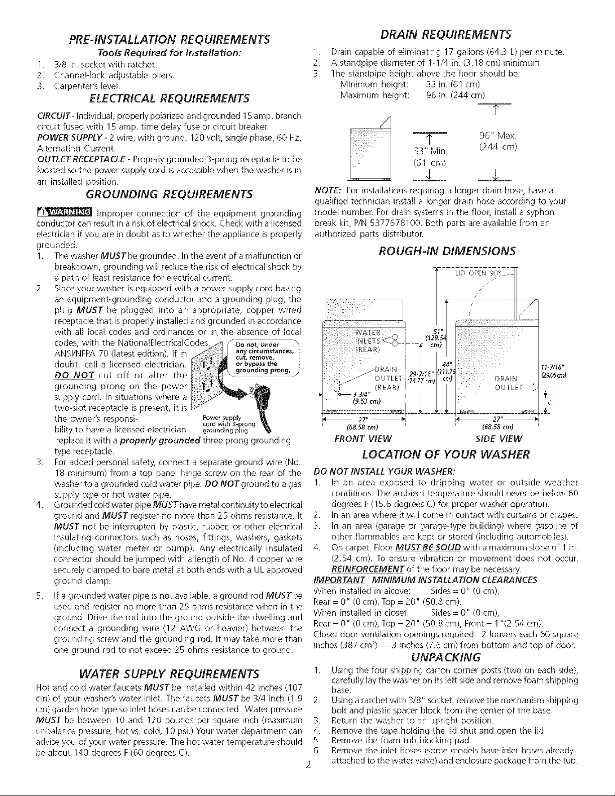
DRAIN REQUIREMENTS
1.
Drain capable of eliminating 17 gallons (64.3 L) per minute.
2.
A standpipe diameter of 1-1/4 in. (3.18 cm) minimum.
3.
The standpipe height above the floor should be:
Minimum height: 33 in. (61 cm)
Maximum height: 96 in. (244 cm)
--T--
_, 96" Max.
33" Min. (244 cm)
(61 crn)
.L __£__
NOTE: For installations requiring a longer drain hose, have a
qualified technician install a longer drain hose according to your
model number. For drain systems in the floor, install a syphon
break kit, P/N 5377678100. Both parts are available from an
authorized parts distributor.
ROUGH-IN DIMENSIONS
VVA_ER _ 51"
NLEfS<J_' 1129.S4
(REAR) •
,,
, OUTLET 29-7/16" (11
I_ 3-3/4"
,J REAR I I
' (9.s3c_)
27"_
(68.58cm)
FRONT VIEW
(74.77cm) c
OUTLETS'/_ "_L
I _ I _
27"_
(6&58cm)
SIDE VIEW
LOCATION OF YOUR WASHER
DO NOT INSTALL YOUR WASHER:
1. In an area exposed to dripping water or outside weather
conditions. The ambient temperature should never be below 60
degrees F(15.6 degrees C) for proper washer operation.
2. In an area where it will come in contact with curtains or drapes.
3. In an area (garage or garage-type building) where gasoline of
other flammables are kept or stored (including automobiles).
4. On carpet. Floor MUSTBE SOLID with a maximum slope of 1in.
(2.54 cm). To ensure vibration or movement does not occur,
REINFORCEMENT of the floor may be necessary.
IMPORTANT MINIMUM INSTALLATION CLEARANCES
When installed in alcove: Sides= 0" (0 cm),
Rear= 0" (0 cm), Top = 20" (50.8 cm).
When installed in closet: Sides= 0" (0 cm),
Rear= 0" (0 cm), Top = 20" (50.8 cm), Front = 1"(2.54 cm).
Closet door ventilation openings required: 2 louvers each 60 square
inches (387 cm 2) 3 inches (7.6 cm) from bottom and top of door.
UNPACKING
1. Using the four shipping carton corner posts (two on each side),
carefully lay the washer on its left side and remove foam shipping
base.
Using aratchet with 3/8" socket, remove the mechanism shipping
bolt and plastic spacer block from the center of the base.
Return the washer to an upright position.
Remove the tape holding the lid shut and open the lid.
Remove the foam tub blocking pad.
Remove the inlet hoses (some models have inlet hoses already
attached to the water valve) and enclosure package from the tub.
11-7/I6"
Page 3

NOTE:
MECHANISM
SHIPPING
BOLT
If the washer isto be transported at alater date, the tub
blocking pad, shipping bolt, and plastic spacer block
should be retained.
PLASTIC SHIPPING BLOCKS
..... SPACER
BLOCK
CABLE TIE
FOAM /
SHIPPING >OWER
PAD CORD
7. From the back of the washer, remove the wire shipping clips
securing the drain hose and power cord. On some models,
PLASTICCLAMPS secure the drain hose to the right side of the
washer backsheet. These clamps form a standpipe to prevent
water siphoning. DO NOT REMOVE THESE CLAMPS.
8. Carefully move the washer to within 4 feet of the final location
for the start of the installation.
SHIPPING CARTON
CORNER POSTS/ DRAIN HOSE
INSTALLATION
1. Run some water from the hot and cold faucets to flush the water
lines and remove particles that might clog up the water valve
screens.
2. Check inlet hoses to ensure that the rubber washers are installed
in each end (If your washer has inlet hoses already attached to
the water valve, proceed to step 4).
3. Carefully connect the inlet hoses to the water
valve (on the left side of the washer cabinet),
tighten by hand, then tighten another 2/3 turn
with pliers.
OVERTIGHTEN THESE CONNECTIONS.
4. Determine which water faucet is the HOT
water faucet and carefully connect the bottom inlet hose he
HOTwater faucet, tighten by hand, then tighten another 2/3
turn with pliers. Carefully connect the top inlet hose to the COLD
water faucet, tighten by hand, then tighten another 2/3 turn
with pliers. _ DO NOT CROSS THREAD OR
OVERTIGHTEN THESE CONNECTIONS.
Turn the water on and check for leaks at both connections.
B. Excessive noise and vibration can be prevented by properly
leveling the washer. For free standinq installation and with the
washer in it's final position, place a level ontop of:he washer.
Adjust the leveling legs so the washer is level front-to-rear and
side-to-side, and stable corner-to-corner.
DO NOT CROSS THREAD OR
CABLE TIE
6. Form a "U" shape on the end of the drain hose with the hose
pointed toward the drain. On some models, a wire retainer needs
to be assembled on the hose in that position. Place the formed
end in a laundry tub or a standpipe and secure with a cable tie
provided in the enclosure package.
NOTE: The standpipe inside diameter must be 1-1/4" (3.18
cm) minimum. There must be an air gap around the
drain hose in the standpipe. A snug hose fit can cause
a siphoning action.
7. Plug the power cord into a grounded outlet.
NOTE: Check to ensure the power is off at a circuit breaker/
fuse box before plugging the power cord into an
outlet.
8. Turn on the power at a circuit breaker/fuse box.
9. Read the Operating Instructions and Owner's Guide provided
with the washer. They contain valuable and helpful information
that will save you time and money.
10. Run the washer through a complete cycle. Check for water leaks
and proper operation.
11. If your washer does not operate, pleasereview the "Avoid Service
Checklist" located in your Owner's Guide before calling for service.
12. Place these instructions in a location near the washer for future
reference.
NOTE: A wiring diagram is located inside the washer console.
REPLACEMENT PARTS
If replacements parts are needed for your washer, contact the source
where you purchased your washer or call 1-800-451-7007 for the
Frigidaire Company Authorized Parts Distributor nearest you.
Destroy the carton and plastic bags after the washer is
unpacked. Children might use them for pla_z Cartons covered with
rugs, bedspreads, or plastic sheets can become airtight chambers
causing suffocation. Placeall materials in a garbage container or make
materials inaccessible to children.
Pressdown on alternate corners and sides and feel for the
slightest movement. Adjust the appropriate leg so the washer
is SOLID on the floor on ALL four legs. Keep the leveling leg
extension at a minimum for best performance of the washer.
The instructions in this manual and all other literature
included with this washer are not meant to cover every possible
condition and situation that may occur. Good safe practice and caution
MUST be applied when installing, operating and maintaining any
appliance.
Maximum benefits and enjoyment are achieved when all the
Safety and Operating instructions are understood and practiced
as a routine with your laundering tasks.
Page 4

REQUISITOS ANTES DE LA INSTALACION
Herramientas necesarias para lainstaladon:
1. Llava de tubo de 3/8 de pulgada.
2. AlicatesajustablesChannel-lock
3. Niveldecarpintero
REQUISITOS ELECTRICOS
CIRCUITO - Circuito derivado individual, correctamente
polarizado y con toma detierra, de 15amperios con fusible
de 15 amperios con retardo o disyuntor.
ALIMENTACiON ELECTRICA - Corriente alterna
monof_isica, 60 Hz, 120 voltios, bifilar, con toma de tierra.
TOMACORRIENTES- EItomacorrientescon 3orificiosytoma
detierra correcta, debe estar ubicadode manera que elcable
electrico sea accesible cuando la lavadora este instalada.
REQUISITOS PARA LA TOMA DE TERRA
Laconexion incorrecta del conductor
de toma detierra deeste equipo puede causar un riesgo de
descargaselect ricas.Consulte aun electricista licenciado si
no estaseguro sielelectrodomestico est.1bienconectado a
tierra.
1. La hvadora DEBEser conectada a una toma de tierra.
Encasode un mal fundonamiento o una falla, la toma
de tierra reduce el riesgo de descargas electricas
proporcionando a la corriente electrica una via con
menos resistenda.
2.
Yaque su lavadora esta equipada con un cableelectrico
que Ilevaun conductor para toma detierra yun enchufe
para toma de tierra, el enchufe DEBE ser insertado en
un tomacomentes adecuado, con hilos de cobre, que
este instalado y conectado a tierra segun todos los
codigos y ordenanzas locales, o si no existen c0digos
locales, con los National Electrical Codes (Codigos
Electricos Nacio alesk ANSI/NFPA70 da edicion mas
reciente). Sino esta BAIONtNUNA
seguro, Ilame a un
electricista licenciado.
NO corte ni modifique la
davija de toma de tierra
del cable electrico. En
casosen que s01ohaya
un tomacomentes de
dos orificios, sera
responsa-bilidad del s_sP_6As
propietario hater que un electricista licenciado Io
cambie por un tomacorrientes de 3 orificios con la
toma de tierra adecuada.
3.
Para mayor seguridad personal, conecte un hilo de
toma de tierra separado (N° 18 como minimo)desde
un tornillo del panel superior en la parte posterior de
la lavadora a una tuberia de agua con conexiOn a
tierra. NO Io conecte a una tubeda de gas ni de
agua caliente.
' CIRCUNSTANCIA
4. La tubena de agua fria con conexi0n a tierra DEBE
tenet continudad metalica hacia la conexi0nelecticia
a tierra y DEBE registrar una resistencia no mayor de
25 ohmios. NO DEBEestarinterru mpida por conectores
de pl_istico,caucho ni otros conectores de aislamiento
el(_cticotales como mangueras, acopladores, arandelas,
juntas (induyendo un contador o una bomba de agua).
Cualquier conector el_cticamente aislado debe ser
conectado en puente con un trozo de alambre de
cobre N° 4 firmemente sujeto en ambos extremos al
metal desnudo con una abrazadera de toma de tierre
aprobada por U.L.
5. Si no se dispone de una tuberia de agua de puesta a
tierra, se DEBE usar una varilla de tierra y registrar
una resistencia no mayor de 25 ohmios cuando este a
tierra, Entierre la varilla fuera de la vivienda y
conecte el abmbre de toma de tierra (AWG 12 o
mayor) entre el tornillo y la varilla de tierra. Puede ue
se requiera mas de una varilla de tierra para no
exceder el valor de resistencia a tierra de 25 ohmios.
REQUISITOS PARA EL
SUMINISTRO DE AGUA
LasIlavesde agua caliente y fria DEBEN estar instaladas a
menos de 42 pulgadas (107 cm) de la toma de agua de la
lavadora. LasIlavesDEBEN serdel tipo manguera dejardin
de 3/4 de pulgada (1,gcm) pala que selespuedan conectar
lostubos de entrada deaguaLa presion del aguaDEBEestar
entre 10y 120 libraspor pulgada cuadrada(presion maxima
de desequilibrio, caliente cont_a fria, 10 libras por pulgada
cuadrada). Sucompaflia desuministro deagua puededecirle
cualeslapresion del agua. Latemperatura delagua caliente
debe ser de unos 140 glados F(60 grados C).
REQUISITOS PARA EL DRENAJE
1. Drenaje que pueda eliminar 17 galones (64,3 L) por
minuto.
2. Diametro de latuberia vertical de I-1/4 pulgadas(3,18
cm) como minimo.
:3. Laaltura de la tuberia vertical por encima del piso debe
ser:
AItura minima: 33 pulgadas(61 cm)
AItura maxima: 96 pulgadas (244 cm)
-7--
q. 96" Max.
33" Min. (244 cm)
(61 cm)
$ $
NOTA:
Paralasinstalaciones que requieran un tubo de drenaje
mas largo, pida a un tecnico capacitado qui instale un
tubo maslargo segun el numero desu modelo.Para los
systemas de drenaje el piso, instale un juego para
detener la accion de sif0n, N° de pieza 5377678100.
Ambos componentes estan disponible en los
distribuidores autorizados de piezasde repuesto.
4
Page 5

DIMENSIONES PARA LA INSTALACION
(1_
(ATRAS) *
SALIDA
AL DREN 29 7,1_¢'
] (ATRAS) (74.77 em
_334"
9.._3 cm)
(68,5_ cm)
VISTAFRONTAL
'_4
I11,"6
_m/ _,UDA
(68.58 cm)
VISTALATERAL
11 7/16"
UBACACION DE SU LAVADORA
NO INSTALESU LAVADORA:
I. En un area expuesta a goteos de qgua o a la
intemperie. La temperature ambiente nunca deber_i
estar por debajo de los 60 grados F(15,6 C) para que
su Bvadora funcione correctamente.
2. En un _ireadonde estara en contacto con persianas o
cortinas.
3. En un area (garaje o construccion similar) donde haya
o se almacene gasolina u otros productos inflamables
(inclusive automoviles).
4. Sobre una alfombra. El piso DEBE SER DURO con
una inclinacion maxima de 1 pulgaga pot pie (1,54
cm). Paraasegurarse de que no existan vibraciones ni
ruidos, puede ser necesario REFORZAR el piso.
IMPORTANTE
DESPEJESMINIMO5 DEINSTALAC!ON
Instalaci0n en una alcoba: Lados, Parte Trasera = 0 cm
(0 pu[g.), Parte Superior = 20 cm (50,8 pulg.)
InstalaciOn en un armario: Lados, ParteTrasera = 0 cm
(0 pu[g.), Parte Superior = 20 cm (50,8 pu[g.), Parte
De[antera = 2.54 corn (1 pulg.)
Aberturas de venti[acion requeridas en [a puerta del
armario: Dosrejillas de ventilacion cada387 cm2(60 pulg))
- 7.6 cm (3 pulg.) desde la parte inferior y superior de la
puerta.
DESEMPAQUE
1. Utilizando las cuatro esquineras de la caja de carton
(dos en cada lado), haga descansar cuidadosamente
la lavadora sobre el lado izquierdo y saque la base de
espuma de embarque.
2. Utilizando la Ilave de tubo de 3/8 de pulgada, saque
ei perno de embarque y el bloque espaciador de
plastico del centra de la base.
NOTA: si lavadora va a set transportada a otto
lugar posteriormente, conserve la espuma de
bloqueo de la tina, el perno de embarque y el
espadador de pl_stico.
BLOQUE DE
29.05 cm)
PERNO DE
EMBARQUE
ESPUMA
PROTECTORA
DE EMBARQUE
BLOQUE EMBARQUE
..ESPACIADOR
DE PLASTICO
ESQUINERAS DE
EMBARQUE DE LA_
CAJA DE CARTON DE DESAGUE
3. Vuelva a colocar la lavadora en la posicion vertical.
4. Quite la cinta que mantiene la tapa cerrada y abra la
tap&
5. Saque la pieza de espuma que bloquea la cavidad.
6. Saque lostubos de entrada de agua (algunos
modelos
tienen los tubos de entrada de agua ya acoplados a
la valvula de agua) y el paquete.
7. Saque las pinzas metalicas del embalaje de la parte
posterior de la lavadora, que sujetan el tubo de
drenaje y el cable electrico. En algunos modelos hay
ABRAZADERA5 DE PLASTICOque sujetan el tubo de
drenaje en el lado derecho del respaldo de la
lavadora. Estasabrazaderas forman una tuberia
vertical para
prevenir el sifonaje de agua. NO SAQUE ESTAS
ABRAZADERAS.
8. Con cuidado, mueva la [avadora a cuatro pies de su
ubicacion definitiva para la instalaci6n final.
INSTALACION
I. Deje correr un poco de agua de las Ilavesde agua
caliente y fria para vaciar las lineas y eliminar las
particulas que pueden obstruir las rejillas de las
valvulas de agua.
2. Examine los tubos de entrada de agua para
asegurarse
de que las arandelas de caucho esten instaladas en
cada extremo. (Si su Bvadora tiene lostubos
acoplados a la valvula de agua, siga con
el paso 4).
3. Comecte con cuidado los
tubos de entrada a la
valvula de agua (en el
lado izquierdo de la
lavadora), apriete a mano
y luego apriete 2/3 de
vuelta con unos alicates.
NO ESTROPEELAS ROSCAS
NI APRIETE ESTASCONEXIONES EXCES!VAMENTE.
:ORDON
ELECTRICO
MANGUERA
Page 6

4. Determine cu_fllde las Ilaves de agua CALIENTEy
conecte con cuidado el tubo inferior de entrada a la
Ilavede agua CALIENTE, apriete a mano y luego apriete
2/3 de vuelta con unos alicates. Conecte con cuidado
el tubo superior de entrada a lallave de agua FRIA,
apriete a mano y luego apriete 2/3 de vuelta con unos
alicates.
NO ESTROPEELAS ROSCAS N!
APRIETEESTASCONEX!ONES EXCESIVAMENTE.
Abra la Ilave del agua y compuebe que no haya fugas
en ninguna de las dos conexiones.
5. La nivelacion del ruido y de la vibracion excesivos de
la lavadora puede ser prevenida correctamente
nivelando la lavadora. Para la instalacion derecha
libre y con la lavadora en ella est_ la posicion final,
pone un nivel encima de la lavadora. Ajuste las
piernas de nivelacion asi que la lavadora es, y
esquina-a-esquina estable de adelante hacia atras y
de lado a lado liana. Presione abajo en esquinas y
lados alternos y sientase para el movimiento mas
leve. Ajuste la pierna apropiada asi que la arandela
es SOLIDA en el piso en las cuatro piernas. Guarde la
extension de nivelacion de la pierna en un minimo
para el mejor funcionamiento de la lavadora.
NOTA: el diametro interno de la tuberia vertical
debe ser de 1-1/4 pulgadas (3,18cm)
como minimo. Debe haber un espacio de
aire alrededor deltubo de drenaje en la
tubeda vertical. Un tubo sin huelgo
puede causar una accion de sifonaje.
7.
Enchufe el cable en un tomacorrientes con toma de
tierra.
NOTA: Asegurese de que la corriente este cortada
enel disyuntor/caja de fusibles antes de
enchufar el cable en el tomacorrientes.
8. Encienda la corriente en eldisyuntor/caja de fusibles.
9. Lea lasInstrucciones para el funcionamiento y la Guia
del propietario incluidas con la lavadora. Contienen
informacion valiosay util que le ahorrara tiempo y
dinero.
I0. Hagafu ncionar la lavadora durante un ciclo
completo. Compruebe que no hayafugas de agua y
que funcione correctamente.
11. Sisu lavadora no funciona, lea la "Lista de
comprobacion para evitar el servicio" que se
encuentra en la Guia del propietario, antesde Ilamar
al servicio tecnico.
12. Guarde estasinstrucciones en un lugar cercano a la
lavadora para poder referirse a eliasen el futuro.
6. Forma una "U" en el extrmo del tubo de drenaje co el
tubo senalando hacia el drenaje. En alginos modelos,
hay que colocar un retenendor metalico en el tubo para
mantenerlo en esa posicion. Coloque el extremo
formado del tubo de drenaje en un oavadero or una
tuberia vertical y fijelo con suj sujetacables incluido en
el paquete.
DE ALAMBRE
NOTA: Dentro de la lavadora, en el panel de servicio, se
encuentra un diagrama de cableado.
PIEZAS DE REPUESTO
Si necesita piezas de repuesto para su lavadora, acuda al
establecimiento donde la compro.
Desechela caja de carton y las bolsas
de plastico una vez que haya desembalado la lavadora.
Los ninos podrian usarlas para jugar. Lascajas de carton
tapadas con alfombras, colchas u hojas de plastico pueden
convertirse en c_irnaras hermOticas, causando asfixia.
Coloque todos los materiales en el basurero o evite que los
ninos tengan acceso a ellos.
_.__ Las instrucciones que aparecen en
este manual y las demas guias incluidas con esta lavadora
no pretenden cubrir todas las condiciones y situaciones
posibles que pueden ocurrir. DEBE tenerse sentido comun
y cuidado al instalar, operar mantener cualquier
electrodomestico.
Seobtiene el maximo de beneficios y resultadoscuando
todas lasinstruccionesde seguridady de funcionamiento
son comprendidas y puestas en pr_ctica de forma
rutinaria cada vez que se lava la ropa.
d
 Loading...