

White-Westinghouse SGR351HS0, SGR351HS1, SGR641HQ0, SGR641HS1, SGR641HS0 Installation Guide
...Page 1
installation instructions
Instrucciones pa
="nstalaci"
_!iii_, _i_'%_ _%_i _i! "_¸ iY% _ _%_i _i _ "_ _
la
\
PiN 134169100F (0804) Printed in U.S.A.
Page 2
CONTENTS
Pro-Installation Requirements .......................................................................................................................................... 2
Electrical Requirements .................................................................................................................................................. 3
Gas Supply Requirements ............................................................................................................................................ 3
Exhaust System Requirements ...................................................................................................................................... 3-4
Location of Your Dryer................................................................................................................................................. 4-5
Mobile Home Installation ............................................................................................................................................... 5
Rough-in Dimensions ..................................................................................................................................................... 6
Unpacking ................................................................................................................................................................... 7
Reversing Door Swing ................................................................................................................................................. 8
Gas Connection ............................................................................................................................................................ 8
General Installation ....................................................................................................................................................... 8
Replacement Parts........................................................................................................................................................ 8
EspaF_ol...................................................................................................................................................................... 9-I4
SAFETY INSTRUCTIONS
Clothes dryer installation and service must be performed by a qualified installer, service agency or the gas supplier.
Install the clothes dryer according to the manufacturer's instructions and local codes•
Before beginning installation, carefully read these instructions. This will simplify the installation and ensure the dryer
is installed correctly and safely. Leave these instructions near the Dryer after installation for future reference•
NOTE: The electrical service to the Dryer must conform with local codes and ordinances and the latest edition of the National
Electrical Code, ANSI/NFPA70, or in Canada, the Canadian electrical code C22.1 part 1.
NOTE: The gas serviceto the Dryer must conform with local codesand ordinances and the latest edition of the National Fuel Gas
Code ANSI Z223.I, or in Canada, CAN/ACG B149.1-2000
NOTE: The Dryer isdesigned under ANSI Z 21.5.1 or ANSI/UL 2158 - CAN/CSA C22.2 No. I 12 (latest editions) for HOME USE
only. This Dryer is not recommended for commercial applications such as restaurants or beauty salons, etc.
Your safety and the safety of others is very important.
We have provided many important safety messagesin the Use & ClareGuide, Operating instructions, Insta%tion Instructions and
on your appliance. Always read and obey all safety messages.
This istt_e safety alert symbol. This symbol alerts you to hazards ttlat can kill or hurt you or others. All safety messages
will be preceded by the safety alert symbol and the word "DANGER" or "WARNING". These words mean:
_ You will be killed or seriously injured if you don't follow instructions.
_ You can be killed or seriously injured if you don't follow instructions.
All safety messages will identify the hazard, tell you how to reduce the chance of injury, and tell you what can happen if the
instructions are not followed.
_"" RISK OF FIRE. Foryour safety the information in this manual must be followed to minimize the risk of fire or
explosion or to prevent property damage, personal injury or loss of life. SAVE THESEINSTRUCTIONS.
- Do not store or use gasoline or other flammable vapors and liquid in the vicinity of this or any other appliance.
- WHAT TO DO IF YOU SMELL GAS
• Do not try to light any appliance.
• Do not touch any electrical switch; do not use any phone in your building.
• Clear the room, building or area of all occupants.
• immediately call your gas supplier from a neighbor's phone. Follow the gassupplier's instructions.
• If you cannot reach your gas supplier, call the fire department.
Installation and service must be performed by a qualified installer, service agency or the gas supplier.
PRE-INSTALLATION REQUIREMENTS
Tools and Materials Required for Installation:
1. Phillips head screwdriver.
2. Channel-lock adjustable pliers.
3. Carpenter's level.
4. Flat or straight blade screwdriver.
5. Duct tape.
6. Rigid or flexible metal 4 inch (I0.2 cm) duct.
7. Vent hood.
8. Pipe thread sealer (Gas).
9. Plastic knife.
2
Page 3
ELECTRICAL REQUIREMENTS
[ GASD er I
1. The dryer isequipped with a three-prong (grounding) plug
for your protection against shock hazard and should be
plugged directly into a properly grounded three-prong
receptacle. Do not cut or remove the grounding prong from
the plug.
CIRCUIT - Individual 15
amp. branch circuit
fused with a I5 amp.
maximum time delay NOTE;Do not
fuse or circuit breaker, underany I '
POWER SUPPLY- 3 wire, remove \
120 volt single phase, 60 grounding \/
Hz,Alternating Current. prong from _ _ PRONG
POWER SUPPLY CORD - plug,
The dryer isequipped with
a 120 volt 3-wire power
cord.
circumstances_
GROUNDING
GAS SUPPLY REQUIREMENTS
Replace copper connecting pipe tha t is not
plastic-coated. Stainless steel or plastic-coated brass MUST
be used.
1. InstalBtion MUSTconform with localcodes, or in ttle absence
of localcodes, with the National FuelGasCode, ANSI Z223.1
(latest edition).
2. The gas supply line stlould be of I/2 inch (1.27 cm) pipe.
3. If codes allow, flexible metal tubing may be usedto connect
your dryer to the gas supply line. The tubing MUST be
constructed of stainless steel or plastic-coated brass.
4. The gas supply line MUST have an individual shutoff valve.
5. A 1/8 inch (0.32 cm) N.RT.plugged tapping, accessible for
test gauge connection, MUST be installed immediately
upstream of the gassupply connection to the dryer.
6. The dryer MUSTbe disconnected from the gassupply piping
system during any pressure testing of the gas supply piping
system at test pressures in excessof I/2 psig (3.45 kPa).
7. The dryer MUSTbe isolated from the gas supply piping
system during any pressure testing of the gassupply piping
system at test pressures equal to or lessthan
1/2 psig (3.45 kPa).
EXHAUST SYSTEM REQUIREMENTS
Use only 4 inch (10.2 cm) diameter (minimum) rigid or flexible
metal duct and approved vent hood which has a swing-out
damper(s) that open when the dryer is in operation. When the
dryer stops, the dampers automatically close to prevent drafts
and the entrance of insects and rodents. Toavoid restricting the
outlet, maintain a minimum of 12 inches (30.5 cm) clearance
between the vent hood and the ground or any other obstruction.
The following are specific requirements for
proper and safe operation of your dryer. Failure to follow
these instructions can create excessive drying times and
fire hazards.
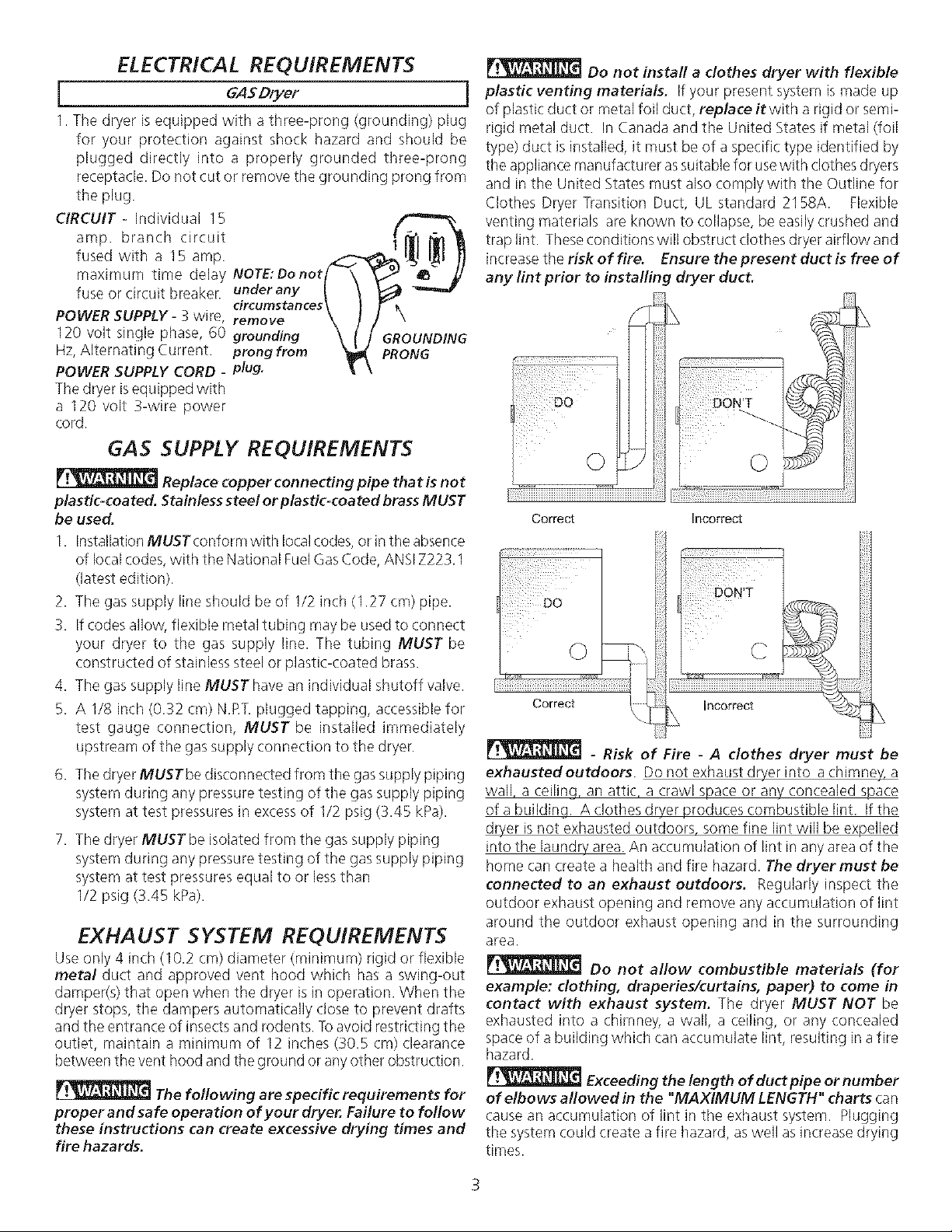
Do not install a clothes dryer with flexible
plastic venting materials. If your present system is made up
of plastic duct or metal foil duct, replace it with a rigid or semi-
rigid metal duct. In Canada and the United States if metal (foil
type) duct is installed, it must be of a specific type identified by
the appliance manufacturer assuitablefor usewith clothes dryers
and in the United States must also comply with the Outline for
Clothes Dryer Transition Duct, UL standard 2158A. Flexible
venting materials are known to collapse, be easilycrushed and
trap lint. These conditions will obstruct clothes dryer airflow and
increase the risk of fire. Ensure the present duct is free of
any lint prior to installing dryer duct.
L
Correct Incorrect
d{{{_!_i
Correct
- Risk of Fire - A clothes dryer must be
exhausted outdoors. Do not exhaust dryer into a chimney, a
wall, a ceilinq, an attic, a crawl space or any concealed space
of a building A clothes dryer produces combustible lint. if the
dryer is not exhausted outdoors, some fine lint will be expelled
into the Bundrv area. An accumulation of lint in any area of the
home can create a health and fire hazard. The dryer must be
connected to an exhaust outdoors. Regularly inspect the
outdoor exhaust opening and remove any accumulation of lint
around the outdoor exhaust opening and in the surrounding
area.
Do not allow combustible materials (for
example: clothing, draperies/curtains, paper) to come in
contact with exhaust system. The dryer MUST NOT be
exhausted into a chimney, a wall, a ceiling, or any conceded
space of a building which can accumulate lint, resulting in a fire
hazard.
Exceeding the length of duct pipe or number
of elbows allowed in the "MAXIMUM LENGTH" charts can
cause an accumulation of lint in the exhaust system. Plugging
the system could create a fire hazard, as well as increase drying
times.
mncorrect
L
Page 4
Do not screen the exhaust ends of the vent
system, nor use any screws, rivets or other fastening means
that extend into the duct and catch lint to assemble the
exhaust system. Lint can become caught in the screen, on the
screws or rivets,dogging the duct work and creating afire hazard
as well as increasing drying times. Use an approved vent hood
to terminate the duct outdoors, andsealall joints with duct tape.
All male duct pipe fittings MUST be installed downstream with
the flow of air.
Explosion hazard. Do not install the dryer
where gasoline or other flammables are kept or stored, if
the dryer is installed in a garage, it must be a minimum of 18
inches (45.7 cm) above the floor. Failure to do so can result in
death, explosion, fire or burns.
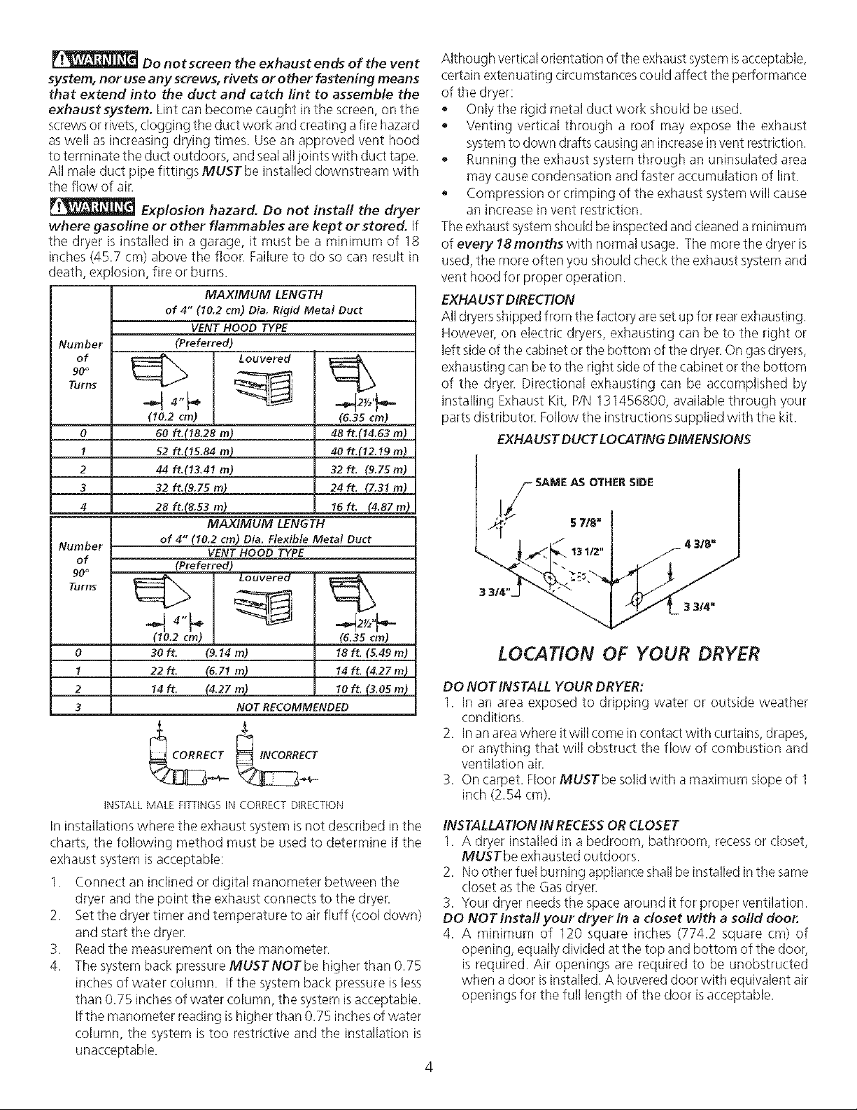
MAXIMUM LENGTH
of 4" (10.2 cm) Dia. Rigid Metal Duct
VENTHOODTYPE
Number (Preferred)
of _ Louvered
Turl'J_;
90°
(10.2 cm)
0 60 ft.(I8.28 m)
1 52 ft.115.84 m)
2 44 ft.(13.4I m)
3 32 ft._9_Z5 m}
4 28 ft_ m__
(6.35cml
48ft.(14.63m)
40 ft._12_9 m)
32ft. (9.75m)
L 24 ft. L7.31 m)
MAXIMUM LENGTH
Number of 4" (10.2 cm) Dia.FlexibleMetal Duct
of (Preferred)
VENTHOODTYPE
Although vertical orientation of the exhaustsystemisacceptable,
certain extenuating circumstancescould affect the performance
of the dryer:
• Only the rigid metal duct work should be used.
• Venting vertical through a roof may expose the exhaust
systemto down drafts causing an increasein vent restriction.
• Running the exhaust system through an uninsuJated area
may causecondensation and faster accumulation of lint.
° Compression or crimping of the exhaust system will cause
an increase in vent restriction.
Theexhaust systemshould be inspectedand cleaned a minimum
of every 18 months with normal usage. The more the dryer is
used, the more often you should check the exhaust system and
vent hood for proper operation.
EXHAUST DIRECTION
All dryers shipped from the factory areset up for rear exhausting.
However, on electric dryers, exhausting can be to the right or
left side of the cabinet or the bottom of the dryer. On gasdryers,
exhausting can be to the right side of the cabinet orthe bottom
of the dryer. Directional exhausting can be accomplished by
installing Exhaust Kit, P/N 131456800, available through your
parts distributor. Follow the instructions supplied with the kit.
EXHALISTDUCTLOCATING DIMENSIONS
Furies
90° _ Louvered
_ _ . (6.35 cm)
0 30 ft. (9.14 m) 18 ft, (5,49 m)
1 22ft. (6.71 m) 14ft, (4,27rn)
2 14 ft, (4.27 m) 10 ft, (3,05 m)
3 NOT RECOMMENDED
INSTALL MALE FI_INGS IN CORRECT DIRECTION
(10.2 cm)
In installations where the exhaust system is not described in the
charts, the following method must be used to determine if the
exhaust system isacceptable:
1. Connect an inclined or digital manometer between the
dryer and the point the exhaust connects to the dryer.
2. Setthe dryer timer and temperature to air fluff (cool down)
and start the dryer.
3. Readthe measurement on the manometer.
4. The system back pressure MUSTNOTbe higher than 0.75
inches of water column. If the system back pressure is less
than 0.75 inchesof water column, the system isacceptable.
ifthe manometer reading ishigher than 0.75 inchesof water
column, the system is too restrictive and the installation is
unacceptable.
LOCATION OF YOUR DRYER
DO NOTINSTALL YOUR DRYER:
1. In an area exposed to dripping water or outside weather
conditions.
2. Inanarea where it will come in contact with curtains, drapes,
or anything that will obstruct the flow of combustion and
ventilation air.
3. On carpet. Floor MUSTbe solid with a maximum slope of 1
inch (2.54 cm).
INSTALLATION IN RECESSOR CLOSET
1. A dryer installed in a bedroom, bathroom, recessor closet,
MUSTbe exhausted outdoors.
2. No other fuel burning appliance shall be installed inthe same
closet asthe Gasdryer.
3. Your dryer needsthe space around it for proper ventilation.
DO NOT install your dryer in a closet with a solid door.
4. A minimum of 120 square inches (774.2 square cm) of
opening, equally divided at the top and bottom of the door,
is required. Air openings are required to be unobstructed
when a door isinstalled. A Iouvered door with equivalent air
openings for the full length of the door isacceptable.
4
Page 5
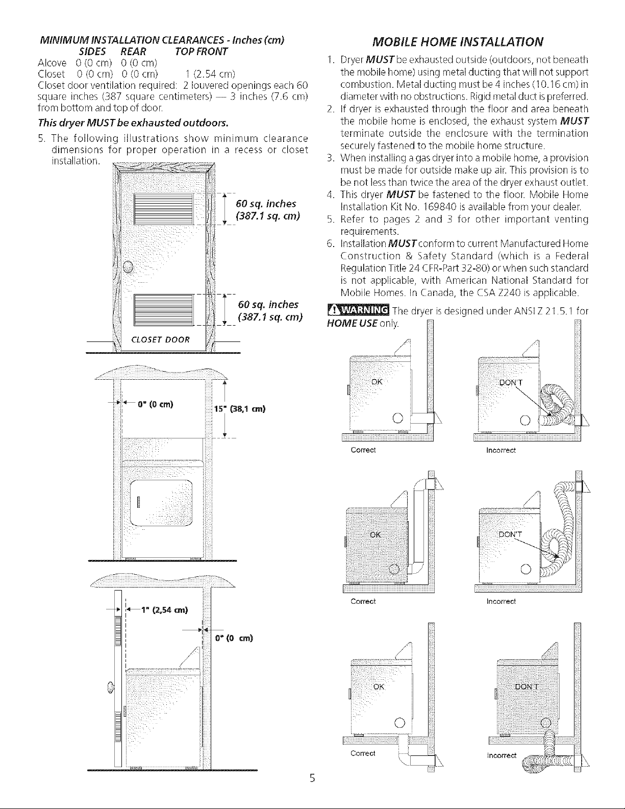
MINIMUM INSTALLATION CLEARANCES -Inches (cm)
SIDES REAR TOP FRONT
Alcove 0(0 crn) 0 (0 cm)
Closet 0 (0 cm) 0 (0 cm) I (2.54 cm)
Closet door ventilation required: 2 Iouvered openings each 60
square inches (387 squale centimeters) -- 3 inches (7.6 cm)
from bottom and top of door.
This dryer MUST be exhausted outdoors.
5. The following illustrations show minimum clearance
dimensions for proper operation in a recess or closet
installation.
60 sq. inches
(387.1 sq. cm)
CLOSET DOOR
i
MOBILE HOME INSTALLATION
1. Dryer MUSTbe exhausted outside (outdoors, not beneath
the mobile home) using metal ducting that will not support
combustion. Metal ducting must be 4 inches (10.16 cm) in
diameter with no obstructions. Rigid metal duct ispreferred.
2. If dryer is exhausted through the floor and area beneath
the mobile home is enclosed, the exhaust system MUST
terminate outside the enclosure with the termination
securely fastened to the mobile home structure.
73.When instaNinga gasdryer into a mobile home, a provision
must be made for outside make up air.This provision isto
be not lessthan twice the area of the dryer exhaust outlet.
4. This dryer MUST be fastened to the floor. Mobile Home
Installation Kit No. 169840 isavailable from your dealer.
5. Refer to pages 2 and 3 for other important venting
requirements.
6. Installation MUSTconform to current Manufactured Home
Construction & Safety Standard (which is a Federal
Regulation Title 24 CFR-Part32-80) or when such standard
is not applicable, with American National Standard for
Mobile Homes. In Canada, the CSA Z240 is applicable.
The dryer
HOME USEonly.
designed under ANSI Z 21.5.1 for
_i_ 0"(Ocrn)
iiiil
Y
if!¸¸¸ o
5i (38,1cm)
Correct Incorrect
i!iii!iiiiiiiiiiiiiii!Ti!iTiii!ili!iii!
_i7_iiiiiiiiiiiiiiiiiiiiiiiiiiiiiiiiiiiiiiiiiiiiiiiiiiiiiiiiiiiiiiiiiiiiiiiiiiiiiiiiiiiiiiiiiiiiiiiiiiiiiiiiiiiiiiiiiiii
Correct Incorrect
o° (o an}
i
Correct
©
Page 6
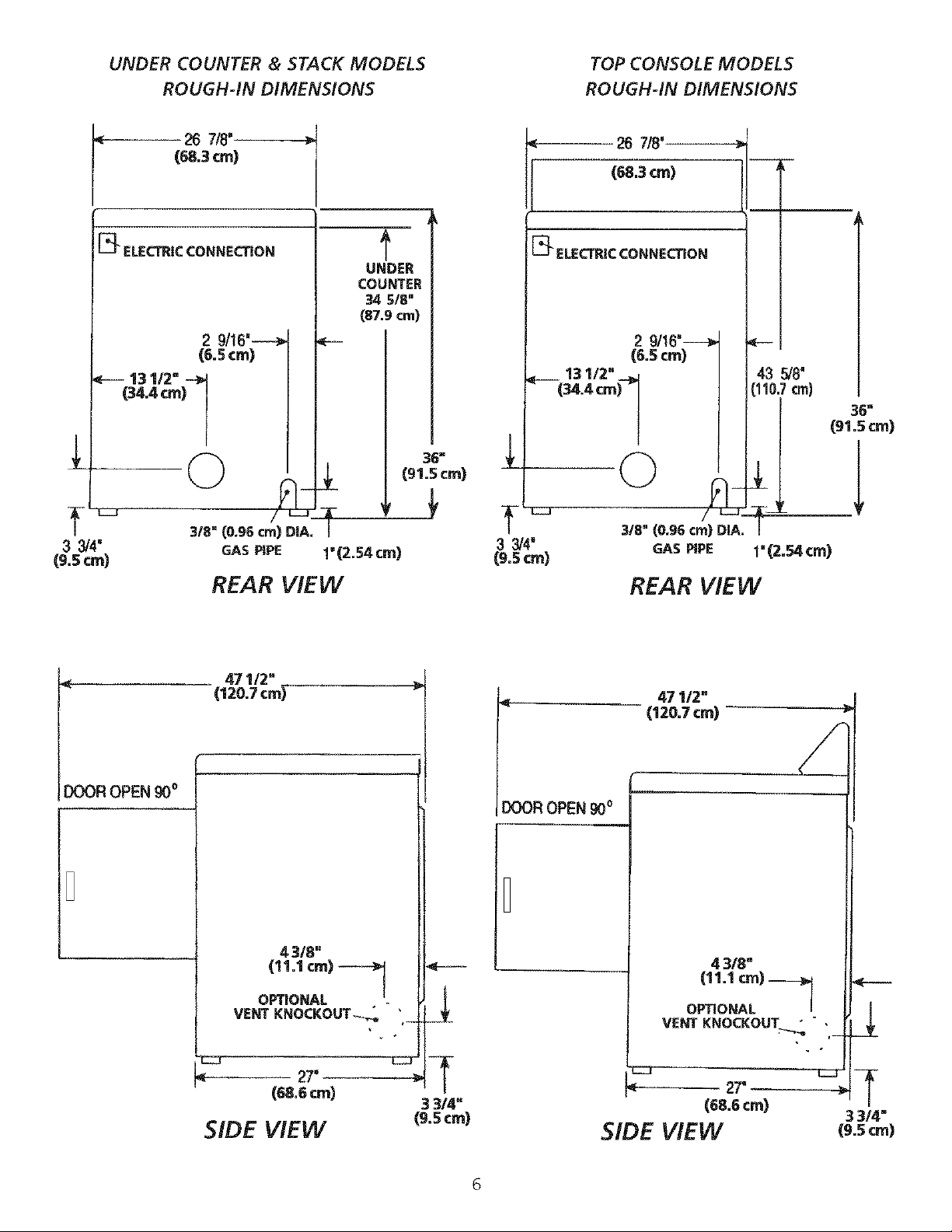
UNDER COUNTER & STACK MODELS TOP CONSOLE MODELS
ROUGH-IN DIMENSIONS ROUGH-IN DIMENSIONS
[_ ELECTRICCONNECTION
(34.4 cm) 1
"EZD
33/4"
(9,5 ¢m)
26 7/8'
(68.3era)
3/8" (0.96 crn) DIA.
GAS PIPE
REAR VIEW
/L_J
T--
UNDER
COUNTER
34 518"
(87.9 cm)
1'(2.54cm)
36"
(91.5 cm)
26 718'.
(68.3cm)
[_ ELECTRICCONNECTION
13 1/2" _...>
(34.4 cm)
0
"EZZi
3 3/4'
(9.5 cm)
3/8" (0.96 crn) DIA, |
2 9/16'-----_
(6.5 cm)
43 _8"
(110.7crn)
36"
(91.5 cm)
F_
GAS PiPE I" (2._ cm)
REAR VIEW
DOOR OPEN 90°
471/2"
(120.7 cm)
mR OPEN _o
4 318"
(11.1 ¢m)
OPTIONAL
VENT KNOCKOUT_,
27_ c:::r
(68.6 ¢m) 27'
3 314" (68.6 cm)
47 1!2"
(I 20.7 ¢rn)
(11.1 cm)
O_ONAL
VE_ KNOCKOUT " "
SIDE VIEW (9.sere) SIDE VIEW
4 3/8"
|
3 3/4"
(9.5 ¢m)
6
Page 7

UNPACKING
REVERSING DOOR SWING
I. Using tile four shipping carton corner posts (two on each
side), carefully laythe dryer on its left side and remove foam
shipping base.
_To prevent damage, do not usethe control panel
as a means to pick up or move the dryer.
NOTE: On under counter model clothes dryers, the top panel
may be removed for installation.
2. Return the dryer to an upright position.
FOAM
SHiPPiNG
PAD
Your dryer is designed so the door swing may be reversed at
any time without additional parts. Conversion isaccomplished
by transferring hinges to the opposite side of the cabinet.
Tochange the direction of the door opening:
1.
Open the dryer door. Remove the four hinge hole plugsfrom
the left side of the door opening. Place nearby for future
installation. NOTE: You may need a plastic knife to help pull
out the plugs. Becareful not to scratch the paint.
2.
Remove the four screws that secure the door hinges to the
dryer front panel (see below). NOTE: Remove one screw
from eachof the two hinges first. Holdthe door firmly before
removing the last two screws.
3. Rotate the door 180° and reinstall the door hinges to the
dryer front panel with the four screws.
4. Install the four hinge hole plugs in the open screw holes on
the right sideof the door opening.
PACKING
\
REMOVE 4 SCREWS
(ONE FROM EACH
HINGE FIRST)
Page 8

INSTALLATION
I. GAS CONNECTlON (Gasdryers on/y)
a. Remove the shipping cap from gas pipe at the rear of the
dryer.
NOTE: DO NOTconnect the dryer to L.Rgas service without
converting the gas valve. An L.R conversion kit must
be installed by a qualified gas technician.
b. Connect a 1/2 inch (1.27 cm) I.D.semi-rigid or approved
pipe from gas supply line to the 3/8 inch (0.96 cm) pipe
located on the back of the dryer. Use a 1/2 inch to 3/8
inch (I .27 cm to 0.96 cm) reducer for a connection. Apply
an approved thread sealer that isresistant to the corrosive
action of liquefied gases on all pipe connections.
c. Open the shutoff valve in the gas supply line.
d. Testallconnections by brushing on asoapywater solution.
NEVER TESTFOR GASLEAKS WITH AN OPEN FLAME.
2. Connect the exhaust duct to outside exhaust system. Use
duct tape to seal alljoints.
13.With the dryer in itsfinal position, adjust one or more of the
legs until the dryer is resting solid on all four legs. Placea
levelon top of the dryer. THEDRYERMUSTBE LEVELAND
RESTING SOLID ONALL FOUR LEGS.
7. If your dryer does not operate, please review the "Avoid
Service Checklist" located in your Owner's Guide before
calling for service.
8. Placethese instructions in a location near the dryer for future
reference.
9. To stack your dryer on a compatible washer call your local
dealer to find your local distributor to purchase a stacking
kit accessory part number 5303937141.
NOTE: A wiring diagram islocated inside the dryer console or
behind the right side panel.
REPLACEMENT PARTS
If replacement parts are needed for your dryer, contact the
source where you purchased your dryer.
Label all wires prior to disconnection when
servicing controls. Wiring errors carl cause improper and
dangerous operation. Verify proper operation after servicing.
Destroy the carton and plastic bags after the
dryer is unpacked. Children might usethem for play. Cartons
covered with rugs, bedspreads, or plastic sheets can become
airtight chambers causing suffocation. Placeall materials in a
garbage container or make materials inaccessible to children.
4. Hug the power cord into a grounded outlet.
NOTE: Check to ensure the power is off at circuit breaker/
fuse box before plugging the power cord into the outlet.
5. Turn on the power at the circuit breaker/fuse box.
Before operating the dryer, make sure the
dryer area is clear and free from combustible materials,
gasoline, and other flammable vapors. Also see that
nothing (such as boxes, clothing, etc.) obstructs the flow
of combustion and ventilation air.
6. Runthe dryer through a cycle check for proper
operation.
NOTE: On gas dryers, before the burner will light, it is
necessaryfor the gas lineto be bled of air.If the burner does
not light within 45 seconds the first time the dryer isturned
on, the safety switch will shut the burner off. If this happens,
turn the timer to "OFF" and wait 5minutes before making
another attempt to light.
The instructions in this manual and all other
literature included with this dryer are not meant to cover every
possible condition and situation that may occur. Good safe
practiceand caution MUSTbe applied when installing, operating
and maintaining any appliance.
8
Page 9

Requerimientos de instalacion preliminares ............................................................................................................................. 10
Requerimientos electricos ..................................................................................................................................................... I0
Requerimientos del suministro de gas...................................................................................................................................... I0
Requerimientos del sistema de escape................................................................................................................................ 10-11
Ubicacion de su secadora .................................................................................................................................................. 11-I 2
Instalacion en casas moviles ................................................................................................................................................. 12
Dimensiones para la instalacion ........................................................................................................................................... 13
Desembalaje ..................................................................................................................................................................... 13
Puerta reversible ................................................................................................................................................................ 13
Instalacion ........................................................................................................................................................................ 14
Piezas de recambio ............................................................................................................................................................ 14
SEGURIDAD de SECADORA
La instalaci6n y el servido de la Secadora de ropa se deben realizar per un instalador calificado, la agencia de servido o el
surtidor de gas.
Instale la Secadora de ropa segun las instrucdones del fabricante y los codigos locales. Antes de comenzar la instalacibn,
lea cuidadosamente estas instrucciones. Esto simplificarb la instalacion y asegurar_ que la secadora se instale correctamente
y de manera segura. Despu_s de completar la instalad6n, coloque estas instrucdones cerca de la secadora para referenda
futura.
NOTA: La alimentad6n el_ctrica para la secadora deber_ cumplir con los c6digos y reglamentos Iocales y con la ultima edition
del Codigo El_ctrico NadonaI, A N$1/NFPA 70o en Canad_ CSA C22.1 Codigo El_ctrico Canadiense, Parte 1.
NOTA: La alimentadbn de gas para la secadora deber,'J cumplir con los c6digos y reglamentos locales y con la ultima edici6n
del Codigo Nadonal para Gases Combustibles, ANSI Z223.1 o en Canad_ CAN/CGA B149.12.
N_ TA: La secad_ra est_ c_asi_cada para US_ D_MES T_C_s_amente_ de acuerd_ c_n _an_rma AN$_ Z21_5.1_ ANSl/UL 2158_
CAN/CSA C22.2No. 112 (las ultimas ediciones). Estasecadora no se recomienda para uso commercial ta l como en restauran tes,
salones de belleza, etc.
Su seguridad y la seguridad de terceros son muy importantes.
Hemos proporcionado muchos mensajes importantes para la seguridad en las Instrucciones de Operacion del Manual de Uso y
Mantenimiento, las Instrucciones de Instalaci6n yen el mismo aparato. Siempre lea y obedezca todos los mensajes para seguridad.
P_Este simbolo significa alerta. Este simbolo Io alerta acerca de peligros que pueden matar o lesionar, tanto a usted como a otras
personas. Todos los mensajes de seguridad seran precedidos por el simbolo de alerta para su seguridad y la palabra "PELIGRO o
ADVERTENCIA " (DANGER" o WARNING.). Estaspalabras significan:
PELIGRO (DANGER) Usted morir_ o resultar_ seriamente lesionado si no sigue las instrucciones siguientes.
ADVER TENCIA(WARNING) Usted puede morir o resultar seriamente lesionado si no sigue las instrucdones
siguientes.
Todos los mensajes de seguridad identificar&n el peligro, le dir&n a usted c6mo reducir la posibilidad de lesi6n y tambi_n
qu_ puede suceder si no se siguen las instrucciones.
_.__ RIESGO DEINCEND!O Parasuseguridad, siga lasinstrucciones contenidas en estemanual a fin de reducir a un
minimo los riesgos de incendio o explosion o para evitar dailos materiales, lesiones personales o la muerte. GUARDE ESTA5
INSTRUCCIONES.
No dma(ene ni utilice gasoli nauotros vapores yliquidos inflamables en la proximidad de esteodecualqu ier otro artefa(to electrico.
QUE DEBE HACERSIPERCIBEOLORA GAS
• Notrate de encender ningOn artefacto electrico.
• Notoque ningOn interruptor electrico; no useningOn telefono ensuedificio.
• Haga salir a todos losocupantes de la habitacion, del edificio ydel Dgar.
• Llame a su proveedor de gas desde el telefono de un vecino. Siga Ds instrucciones del proveedor de gas.
• Sino Iogra comunicarse con su proveedor de gas, Ilamealdepartamento de bomberos.
Lainstalaci6n y elservicio de mantenimiento debe de realizarlos un instalador calificado, la agencia de servicioso el proveedor degas.
REQUERIMIENTOS DE INSTALACION PRELIMINARES
Herramientas y materiales necesarios para la instalacion:
I. Destornillador Phillips
2. Alicates urfiversales
3. Nivel de carpintero
4. Destornillador paratornillo de cabezaplana o recta
5. Cinta paraductos
6. Ducto met:_lico rigido o flexible de 4 "(10,2 cm)
7. Caperuza de salida
8. Se%dor de tubedas (gas)
9. Un cuchillo de pl_%tico
9
Page 10

REQUERIMIENTOS EL£CTRICOS
Secadorasa GAS
Esta secadora esta equipada con un enchufe de tres espigas (de
puesta a tierra) para proteccion encontra de choques electricos y
debe serconectada directamenta en unreceptaculo paratresespigas
el cual debe estar puesto atierra. No torte ni elimine la espiga de
puesta atierra de esteenchufe.
CIRCUITO- Circuito individual derivado de 15amp, con fusibJesde
15 amp. de retardo m_iximo o disyuntor.
ALIMENTAClON ELECTRICA-
Corrientealterna, monof_isica,
60 Hz, 120 voltios, trifilar.
CORDON ELECTRICO-
Lasecadoraesta equipad
conun cord6n electrico
trifilarpara 120voltios.
de! enchufe. TERRA
REQUERIMIENTOS DEL SUMINISTRO DE GAS
F_ Reemplace la tuberia de conexi6n de
cobre que no est_ recubrida con plbstico. El latbn inoxidable
o recubrido con pl_stico DEBESERutilizado.
1. Lainstalaci6n DEBEhacersecumplircon IoscOdigos Iocaleso en
ausenciade losmismos,deacuerdo con losestandaresdelNational
FuelGasCode(C0digo NacionalparaGasesCombustibles), ANSI
Z223.1 (la01timaedition). ParaCanada, el Estandar CAN/CGA
B149 que esteen vigor.
2. La tuberia de alimentaci6n de gas debe ser de 1/2 pulgada
(1,27 cm)de diametro.
3. Siestapermitido por losc6digos locales,se puede usartuberia de
metal para conectar su secadora a la Iineade suministro de gas.
La tuberia DEBE ser fabricada de acero inoxidable o cobre
recubierto de plastico.
4. Latubeda de alimentacidn degasDEBEtener una Ilavedecierre
individual.
5. Una toma de I/8 de pulgada (0,32 cm) N.RT. accesible para
conexion del man0metro de prueba, DEBE ser instalada
inmediatamente aguas ardba de la conexiOn de la tuberia de
alimentacidn de gas a la secadora.
6. Lasecadora DEBE serdesconectada del sistema de tubedas de
alimentaciOn de gas durante cualquier ensayo de presiOn del
sistemade tuberias dealimentaciOn degasrealizado a presiones
de prueba de mas de I/2 Ibs/pulg.2(3,45 kPa).
7. LasecadoraDEBEaislarsedelsistemadetuberiasdealimentacion
degasdurante cualquierensayode presiOndelsistemade tuberias
de alimentacion de gasrealizado en ensayosde presion iguales o
inferiores a I/2 Ibs/pulg.2(3,45 kPa).
REQUERIMIENTOS DEL SISTEMA DE ESCAPE
Utilice solamente ductos metalicos, dgidos o flexibles de 4"
(10,2 cm) de diametro (minimo) y una caperuza de salida de uso
aprobado, con registros que giren haciaafuera que seabren cuando
la secadora se encuentra enfuncionamiento. Cuando la secadora
sedetiene, los registros secierran automaticamente para evitar las
corrientes de aire y la entrada de insectos y roedores. Para evitar
obstruir lasalida,mantenga una altura libre minima de 12"(30,5 cm)
entre lacaperuzade salidayelpiso o entre cualquier otra obstruccidn.
Los siguientes requerimientos son
espedficos para el funcionamiento correcto y seguro de su
secadora, El incumplimiento de estas instrucciones puede
causar prolongacion excesiva del tiempo de secadoy riesgos
de incendio.
[] No instale la Secadora con materiales de ventilaci0n plasticos
fiexibles. EnCanada y los EstadosUnidos sielconducto esde metal
(tipo hoja de aluminio),estedebe serde untipo especificoidentificado
por elfabricante, recomendado para eluso con Secadoras; yen los
EstadosUnidos debe ademas cumplir con la norma UL2158A. Los
materiales de ventilaciOn flexibles se pueden colapsar oapachurrar
f_icilmenteyatrapar pelusa.Estascondiciones obstruiran lacirculaci0n
de aire delaSecadorade ropa yaumentaran elriesgo deincendio.
Sisusistema de escapeactual tiene ductos de plastico o de laminas
metalicas delgadas, _lacelo con un ducto metalico rigido o
flexible. AsegOrese de que los ductos existentes no tengan
pelusas antes de instalar el ducto de la secadora.
i_uii
CORRECTO INCORRECTO
i_iu_i_u_ila_i!_i_i u
!!!i!i!¸¸¸ sl
e
C
INCORRECTO
[] Riesgo de incendio- Lasecadora debe set ventilada al exterior
de lavivienda. Noventile la secadora a una chimenea, pared, techo,
atico, pasaiesentre pisosocualquier espacio oculto de la vivienda.
Lassecadorasde ropa producen pelusacombustible. Sino seventila
lasecadoraal exterior,algunas pelusasfinasseacumularan en elarea
de lavanderia. La acumulaci0n de pelusa en cualquier area de la
vivienda puedeconstituir un peligro sanitarioy un riesgode incendio.
La secadora debe dstar conectada a un sistema de escape que
termine en el exterior de la vivienda. Inspeccione laabertu ra de
escape alexterior con frecuencia y elimine cualquier acumulaci6n
de pelusa en tal abertura yen el area que la rodea.
[] No permita que los materiales combustibles (pot eemplo: la
ropa, cortinas/cortinaies, papel)tenqan contacto con losductos.
[] Excederla Iongitud del conducto rigic[oolosn0meros decodos
permitidos en losdiagramas "LARGOMAXlMO" puede disminuir
lacapacidad deexhaustadon delsistema. Obstruir elconductopuede
provocar peligrodeincendio, asicomoaumentar eltiempo desecado.
[] No obstruva los extremos del tubo de ventihcion, ni utilice
tornillos remaches uotros medios defijadon que puedan obstruir el
conducto yatrapar pelusa. Laspelusaspoddan quedar atrapadas en
losfiltros, en lostornillos oenlosremaches,Iocualobstruida elsistema
de escape ycreanaunriesgodeincendio, asicomotambien
prolongaria el tiempo de secado. Use una caperuza de salida
adecuada paraelextremo delducto que salgaal exterior de lavivienda
y selle todas lasjuntas con cinta adhesiva para ductos. Todos los
accesoriosde tuberia machos, DEBENser instalados aguas abajo del
fiujo de aire.
10
Page 11

r!_ Riesgo de explosion. No instale la secadora
donde se quarda qasolina u otros materiales inflamables. Si la
secadora se instda en un garage, ella debe estar per Io menos 18
pulgadas (45,7 cm)por encima de1suelo. Elincumplimiento puede
resultar enlamuerte, explosion, incendio, o quemaduras.
LARGO MAXIMO
del Cenducto Met_lice Rigido
de 4" (10,2 cm) de Di_metre
TIPO DE CAPERUZA DE SALIDA
(Preferido)
Numero _ Apersianada
de Codo_
ogo°
0 60 pies (18,28 m)
1 52 pies (15,84 m)
2 44 pies (13,41 m)
3 32 pies (9,75 m)
4 28 pies (8,53 m)
LARGO MAXIMO
del Conducto Met&lice Flexible
de 4" (10,2 cm) de Di&metro
TIPO DE CAPERUZA DE SALIDA
(Preferido)
de Codo!
Numero _ Apersianada _
48 pies(14,63m)
40 pies(12,19m)
32 pies (9,75 m)
24 pies (7,31 m)
16 pies (4,87 m)
e Sedebe utilizarsolamente conductos metalicos rigidos.
• Una salida del sistema vertical en el techo, puede exponerle
a uncorriente de aire descendente y disminuir as[sucapaddad
de exhaustacion.
Elaislante que debe atravesar el sistema puede causar
condensacion y disminuir asllacapacidad de exhaustaciOn
del sistema.
Lacapacidad de exhaustacion de un sistema de exhaustadon
comprimido o ondulado puede disminuirse.
E]sistema de exhaustadon debe de set inspeccionado y limpiado
per Iomenos cada 18mesesde usenormal. Cuanto m_islasecadora
esta utilizada, masdebeverificarel buen funcionamiento delsistema
de exhaustacion y de latapa del orifido de ventilacion.
UBICACION DEL ESCAPE
Todaslassecadoras vienen de fabrica equipadas conescape trasero.
Sin embargo, en las secadoras elOctricas,elescapepuede hacerse
al ladederecho o izquierdo del gabinete o en laparte inferior de la
secadora. En lassecadoras a gas, el escape del aire puede estar en
el lade derecho del gabinete o en laparte inferior de la secadora. El
escapedireccional puede efectuarseinstalando un Juegode Escape,
P/N 131456800, disponible a travesdesudistribuidor derepuestos.
Siga lasinstrucciones que sesuministran con eljuego.
DIMENSIONES PARA LA LIB!CACION DELDUCTO DEESCAPE
_- IGUAL QUE ELOTRO LADO
J¢
I J_;.,, s7/8"
] / / (15cra) 4 3/8"
0
1
2 14 pies (4,27m) 10pies (3,05m)
3 NORECOMENDADO
INSTALE LOS ACCESORIO_; MACHOS EN LA DIRECCION CORRECTA
Paralasinstalaci0nescuyassistemadeexhaustacion no seencuentre
en el diagrama, se puede utilizar el metodo acontinuacion para
determinar siel sistema de exhaustacion esapropiado.
1. Conecte un manometro a tube inclinado o digital entre la
secadora yel union de exhaustacion de la secadora.
2. Ponga el contador detiempo de la secadora y la temperatura
a aire frio (enfiriamiento), y la secadora en la posicion de
marcha.
3. Lea la medida indicada enel manometro.
4. La baja presion NO DEBEexceder 0.75 pulgada delacolumna
de agua. Si la baja presion es inferior a 0.75" de la columna
deagua, elsistemaesaceptable. Silalecturaindicauna
presion superior a 0.75" de lacolumna de agua, la capacidad
del circuito esinsuficiente y lainstalacion es inaceptable.
Aungue un sistema vertical seaaceptable, algunas circunstancias
atenuantes pueden afectar elfuncionamiento de lasecadora:
30 pies (9,14m) 18pies (5,49m)
22 pies (6,71m) 14 pies (4,27 m)
UBICACION DE SU SECADORA
NO INSTALESU SECADORA:
1. Enun lugardondepuede habergoteosde aguao quede expuesta
alas inclemencias del tiempo.
2. En un _irea deride pueda entrar en contacto con cortinas,
cortinajes o cualquier otra cosa que obstruya el flujo de
combusti6n yventilaci6n de aire.
3. Sobre alfombras. ElpisoDEBEserfirmecon un desnivel maximo
de I pulgada (2,54 cm).
INSTALA CION DENTRODE UN NICHO OARMARIO
I. Si la secadora es instalada en un dormitorio, cuarto de barlo,
niche o armario, el tube del escapeDEBE serinstalado hacia el
exterior.
2. Nosedebe instalarningun otro artefacto quequeme combustible
en el mismo armario en que est_ instalada la secadora aGas.
3. Lasecadora necesitaespacio asu alrededor paraunaventilaci0n
adecuada.
NO INSTALE LA SECADORA EN UNARMAR/O CON PUERTA
MACIZA.
4. Se requiere come minimo una abertura de 120 pulgadas cua-
dradas (774,2 cm2), dividida equitativamente para la parte
superior e inferior de lapuerta. Cuando seinstalaunapuerta, es
necesarioproveeraberturas para elaire. Unapuerta apersianada
con aberturas para el aire en todo el largo de la puerta es
aceptable.
11
Page 12

DESPEJESM#NIMOS DE INSTALACiON (Puigadas)
PARTE PARTE PARTE
DELANTERA LADOS TRASERA SUPERIOR
Alcoba o
encastradas0(0cm) 0(0cm) 0(0cm) 15(38,1cm)
Armado 1(2,54cm) 0(0cm) 0(0cm) 15(38,1cm)
Ventilaci0n requirida en la )uerta del armario: dos aberturas 2.
rejilladas cada 60 pulg? (387 cm2)--3" (7,6 cm) desde la parte
inferior y superior de lapuetra.
ELTUBO DELESCAPEDELA SECADORA DEBESERINSTALADO 3.
HACIA ELEXTERIOR.
5. Lassiguientes ilustraciOnesmuestran lasdimensiOnesminimas
de espacio libre que debe existir para el buen funcionamiento 4.
de la secadora cuando se instala en un nicho o en un armario.
INSTALAC/ON EN CASAS MOV/LES
I. EltubodeescapedelasecadoraDEBEserinstaladof_adaelexterior
(Elescapedebe colocarse en la parte exteriory nodebajo de lacasa
m6vil.) Debe usarseducto demetal que no seacombustible. Elducto
de metal debe tener cuatro pulgadas (10,16 cm) de diametro y no
tener obstrucciones. Espreferible usarducto de metal que searigido.
Siel tubo de escape de lasecadora corre atrav#_sdel pisoy el area
debajode lacasam6viles cerrada,elducto deescapeDEBEterminar
fuera del recinto, con elextremo final asegurado en contra de la
estructura de la casa movil.
AI instalar unasecadoradegasen una casamovil, hayque instalar
una provision de aire fresco suplementario. Laprovisi6n tiene que
sermasgrande que dosvecesel espacio delescapede lasecadora.
Estasecadora DEBE asegurarse al piso. EIjuego para instalaci0n
en la casa m6vil es el No. 169840 y Io puede adquirir con su
distribuidor.
Vealaspaginas 2y3paraotros requisitosimportantes deventilad0n.
La instalaciOn DEBE cumpNr con las estandares aplicables de la
Manufactured Home Construction & SafetyStandard- Estandares
de SeguridadyConstrucciOn deCasasPrefabricadas(Titulo 24 CFR
- Parte32-80 del Reglamento Federal)o cuando dichosestandares
no sean aplicables, se deben compNr con los estandares de la
American National Standard for Mobile Homes (Estandares
Nacionales Americanas para Viviendas M6viles). EnCanada se
apNcael Estandar CSA Z240.
Estasecadora hasido diser_adaPARA USO
DOMESTICO solamente, de acuerdo con la norma ANSI Z 21._5.1.
PUERTA DEL ARMARIO
O"(0 cm)
_iI i_!i_
iTil¸¸¸¸¸¸¸¸¸sl¸¸ I
n_
iii ii!!!i!i ii!iii!!i!iii i! i !iliiiii!i!!U
Correct Incorrect
L
Correct Incorrect
L
iiiii
i
12
IRcorrect
Page 13

MODEL OS A UTONOMOS
CON CONSOLA SUPERIOR
DIMENSIONES PARA LA INSTALACION
__ 26 7/8"
[_ CONEXION ELECTRICA
2 9/16" (6,5cm)
13 1/2" -_
(34,4 cm)
(68,3 cm)
i
i
i
i
i
I
I
I
43 5/8"
(110,7 era)
DESEMBALAJE
I. Utilizando lascuatro esquinerasdeembarque de lacajadecart0n
(dosa carla lado), coloque cuidadosamente la secadora sobre
el costado izquierdo y saque la basede espuma de embarque.
Paraevitar danos, no useelpanel de control como
un medio para levantar o mover la secadora.
NOTA: Enlosmodelos de secadorasencastradas,elpanel superior
puede ser removido para la instalacion.
2. Vuelva la secadora asu posicion vertical.
PLACA DE
ESPUMA DE
EMBARQUE
L
3 3/4" (9,5 cm)
PUERTA
ABIERTA A 90°
©
CONEXIONDELA I
TUBERIADE GAS 1" (2, 54 cm)
DE3/8" (0,96cm)
VISTA POSTERIOR
47 1/2"
(120,7 cm)
/_-J,
36 _l
_UE
PUERTA REVERSIBLE
Su secadora ha sido diseflada para que la puerta pueda ser
cambiada de lado en cualquier momento sin necesidad de piezas
adicionales. La conversion se hace transfiriendo las bisagras al
lado opuesto del gabinete.
Como cambiar la direction de apertura de lapuerta:
I. Abra la puerta de la secadora. Quite los cuatro receptores del
agujerodela bisagradelladoizquierdodelaaperturadela puerta.
Coloquelosen unlugarcercano para futura instalacion. NOTA:
Puedeque senecesite un cuchillo de pl_isticopara poder sacar
losreceptores. Tenga cuidado de no rayar lapintura.
2. Quite loscuatro tornillos que aseguranlas bisagrasde la puerta
al panelfrontal de lasecadora (verfigura abajo). NOTA: Primero
quite un tornillodecada unade lasbisagras. Mantenga lapuerta
sujetada firmemente antes de quitar losdos ultimos tornillos.
3. Gire la puerta 180° yvuelva acolocar las bisagrasde la puerta
en el panel frontal con los cuatro tornillos.
4. Instale los cuatro receptores de losagujeros de lasbisagras en
los agujeros abiertos en el lado derecho de la apertura de la
puerta.
4 3/8" (11,1 cm)'--_
DISCOOPCI6NAL I
I
REMOVIBLEPARA-_._ "
VENTILACI6N '-
27'
(68,6 cm)
VISTA LATERAL
-'1::::3"
3 3/4" (9,5 cm)
QUITE LOS CUATRO
TORNILLOS (PRIMERO QUITE
UNO DE CADA BISAGRA )
13
Page 14

INS TALA €ION
1. CONEXION DELGAS (._ecadorasa gas solamente)
a. Saque latapa de embarque de la tuberia de gas de la
secadora situada en la parte trasera.
NOTA: NO conecte la secadora al suministro de propano, sin
primeroinstalar eljuego de conversion a propano. EIjuego de
conversion a propano debe serinstalado por untecnico de gas
calificado.
b. Conecte una tuberia semirigida de 1/2" (1,27 cm) D.I.o
una tuberia aprobada, desdelaIineade suministro degas
a la tuberia de 3/8" (0,g6 cm) ubicada en la parte trasera
de lasecadora. Utilice un reductor de 1/2" (1,27 cm) a3/
8" (0,g6 cm) para la conexion. Aplique un sellador de
roscasde uso aprobado, resistente a la corrosion de los
gases licuados, en todas lasuniones de la tuberia.
c. Abra la valvula de cierre en la tuberia de suministro de
gas.
d. Pruebetodas lasconexiones aplicando con unaescobilla
una solucion jabonosa. NUNCA UTILICE UNA LLAMA
ABIERTA PARA DETECTARFUGAS DEGAS.
2. Conecte el ducto de escape al sistema de escape exterior.
Utilice cinta para obturar todas lasuniones.
3. Con lasecadora en suposicion definitiva, regule uno o m_is
tornillos niveladores, hasta que la secadora repose
firmemente sobreIoscuatrotornillos. Coloque un nivelsobre
laparte superior delasecadora.LA SECADORA DEBEESTAR
A NIVEL YREPOSAR$OLIDA YFIRMEMENTESOBRELOS
CUATRO TORNILLOSNIVELADORES.
4. Conecte el cordon electrico a un tomacorriente puesto a
tierra. NOTA:Asegoresedeque lacorrienteestedesconectada
en el disyuntoWcaja de fusibles, antes de conectar el cordon
electrico en el tomacorriente.
5. Conecte lacorriente en el disyuntor/caja de fusibles.
Antes de poner en funcionamiento la
secadora, asegurese de que no haya materiales
combustibles, gasolina y otros vapores inflamables cerca
de la secadora. Adem_s asegurese de que no haya nada
(tal como cajas, ropas, etc.) que obstruya el flujo del aire
de combusti6n y ventilad6n.
7. Si su secadora no funciona, consulte la seccion "Lista de
Control de Averias" que se encuentra en su Manual del
Usuario, antes de Ilamar para obtener servicio.
8. Conserve estas instrucciones cerca de la secadora para
referencia futura.
9. Paraapilar suSecador en unaLavadora compatible Ilame a su
distribuidor local paraencontrar sudistribuidor localycomprar
el numero de parte 5303937141 - accesorio demontaje.
NOTA: Dentro de laconsola de la secadora o debajo del panel
superior seencuentra undiagrama del cableado.
PIEZAS DE RECAMBIO
Sinecesitaobtener piezasde recambioparasusecadora,pongase
en contacto con el distribuidor donde compro susecadora.
Cuando sereparan loscontroles, marque todos
loscablescon etiquetas antes dedesconectados. Cualquier error
de cableado puede causar una operation inadecuada ypeligrosa.
Aseg0resede que lasecadora funcione adecuadamentedespu_s
de repararla.
r_ Destruya la caja de carton, bs bolsas de
pl_isticoy la banda met_lica despues de haber desempacado el
centro de lavanderia. Los nifios pueden ponerse a jugar con
ellos. Lascajas de carton cubiertas con alfombras, colchas o
pedazos de plastico pueden convertirse en camaras sin aire y
causar asfixia. Elimine todos los materiaies poniendolos en la
basura o fuera del alcance de los nihos.
Lasinstrucciones incluidas en este manual y
en el resto de la documentaciOn que seentrega con la secadora
no pueden cubrir todas lassituaciones o condiciones posiblesque
puedan presentarse. Por Io tanto, se DEBEN seguir practicas
seguras y tener cuidado cuando se instah cualquier artefacto
domestico.
6. Haga funcionar lasecadora durante un ciclo completo para
comprobar subuen funcionamiento.
NOTA: En las secadoras a gas, antes de encender el
quemador es necesario purgar el aire de latuberia del gas.
Sielquemador no enciende dentro de 45 segundos, cuando
la secadora se enciende por primera vez, el interruptor de
seguridad apagara el quemador. Si esto sucede, gire el
contador detiempo a la posicion "OFF" (apagado)y espere
5 minutos antes de intentar encender la secadora
nuevamente.
14
 Loading...