

Page 1
Thermostat With Humidity Control
Digital 7-Day Programmable
WHITE-RODGERS
TM
90 Series
P R E M I U M
1F95-391
Operating Instructions
Retain for Future Use
Page 2
Easy, Menu-Driven Set-Up
and Programming
8
1
765432
9
10
11
12
Premium options
to customize the thermostat
to fit your application.
17
16
15
14
13
Page 3
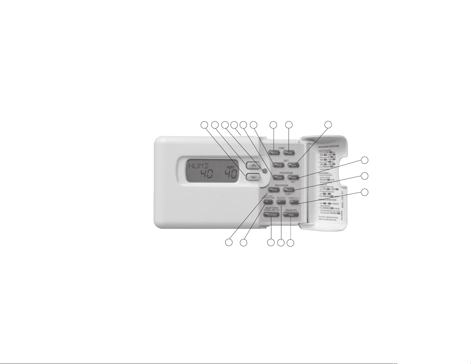
ORIENTATION
THE THERMOSTAT BUTTONS
See inside front cover for illustration
showing button locations.
(Blue arrow) Lowers temperature
1
setting (45
2
setting (99
3
green for 1st stage, yellow for 2
flashing yellow for 3rd stage, red for
emergency heat and flashing red for
malfunction condition in system.
4
lights the display.
5
thermostat programming or advance to
next program period in programming
mode.
Introduction
°F or 7°C minimum)
(Red arrow) Raises temperature
°F or 37°C maximum)
The multi-color indicator glows:
nd
stage,
This button (on top of the cover)
Used to initiate or review
Configuration
Used with TIME
6
to set the clock.
BACK
Used to adjust the time backward,
7
FWD
or to select the previous menu item.
Used to adjust the time forward, or
8
to select the next menu item.
Used with TIME
9
to set the current day.
BACK
Used to advance operation to the
10
FWD
next program period or advance to the
next day in programming mode.
Used to manually override
11
programming to hold at a selected
temperature.
Used to view ambient humidity or
12
modify humidity setting.
1
Programming
Features
/TIME
/TIME
Selects fan operation (see The
13
Display page
3). This button is also
used to program the fan to run
continuously during a program period.
Used to enter the service menu to
14
change or reset humidifier, air filter,
UV bulb, and service timers.
Sets the system mode (HEATing,
15
EMERgency (Heat Pump models
only), OFF, COOLing, or
AUTOmatic changeover).
Used to adjust the clock one hour
16
forward or back.
Used to start or return to program
17
operation.
FAQs
Troubleshooting
Index
Page 4
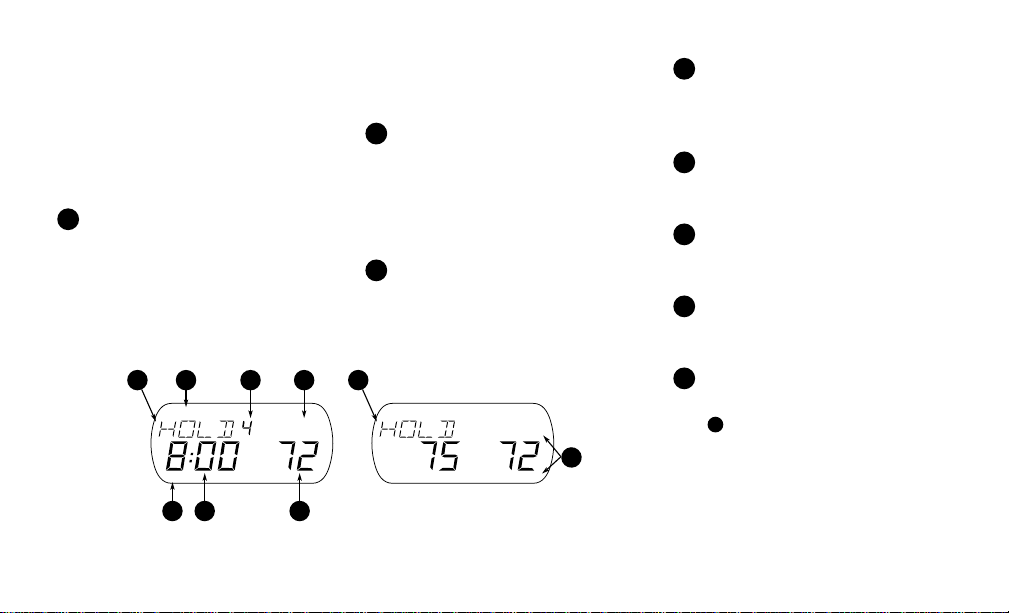
LARGE LIGHTED (LCD) DISPLAY
The thermostat display alternately
shows the current time and the current
temperature on the left side. The
display also shows the temperature
you have programmed or set on the
right side of your screen.
Display system mode (OFF,
1
AUTO, HOLD, VACA or HUMD).
During programming displays the time
period (MOR, DAY, EVE, NHT)
being programmed. In the configuration menu, the menu item name is
1 1
2 3 4
CHECK STAT SYSTEM
MON
FAN AUTOHRS
°F
AM
shown, one word at a time (PRGM
MODE, EMR, COOL FAN DELA
OFF, etc.).
CHECK STAT appears when the
2
thermostat detects certain problems
within itself. CHECK SYSTEM
appears when the themostat detects
certain problems in the heating/cooling
or humidity system.
Indicates the length of time
3
remaining in a temporary hold
condition. Also indicates the length of
time remaining in VACATION mode.
CHECK BATTERY
MON WED THU FRI SAT SUNTUEWED THU FRI SAT SUNTUE
FAN AUTO
HRS
HEATHEAT
°F
AM
8
Displays FAN ON when the fan is
4
operating continuously. Displays FAN
AUTO when the fan cycles with the
heating or cooling system.
Displays the setpoint temperature.
5
In HUMD mode, shows humidity
setpoint.
Alternately displays room
6
temperature and time of day. In
HUMD mode, shows actual humidity.
Shows the current day of the week.
7
When programming, shows the day(s)
being programmed.
The word HEAT or COOL will
8
appear above or below the setpoint if
1
is needed to display other
area
information.
67
5
2
Page 5

INTRODUCTION
Thank you for purchasing your
new White-Rodgers 90 Series
thermostat with humidity control.
White-Rodgers has been producing
energy saving controls for over 60
years. W e have been designing and
producing the White-Rodgers 90
Series family of electronic programmable thermostats since 1982.
White-Rodgers 90 Series is the
third generation of the electronic
programmable family . We believe
you will find that the WhiteRodgers 90 Series is the most user
friendly and technologically
advanced thermostat and humidity
control available today .
Introduction Configuration TroubleshootingProgramming
Y ou will find information about
thermostat buttons (page 1) and
display beginning on page 2.
Introduction .....................................................3
Configuration ..............................................4-11
Manual Operation and Programming ......12-17
Features .................................................... 18-26
FAQs ......................................................... 27-30
Troubleshooting ....................................... 31-34
Index ...............................................................35
Use the tabs at the bottom of the page to quickly
locate sections.
3
Features
FAQs Index
Page 6
CONFIGURATION
The configuration menu allows you to set thermostat operating characteristics to your system or personal requirements.
FWD
To enter the menu, press TIME
and TIME
menu options. Press arrow keys to change options.
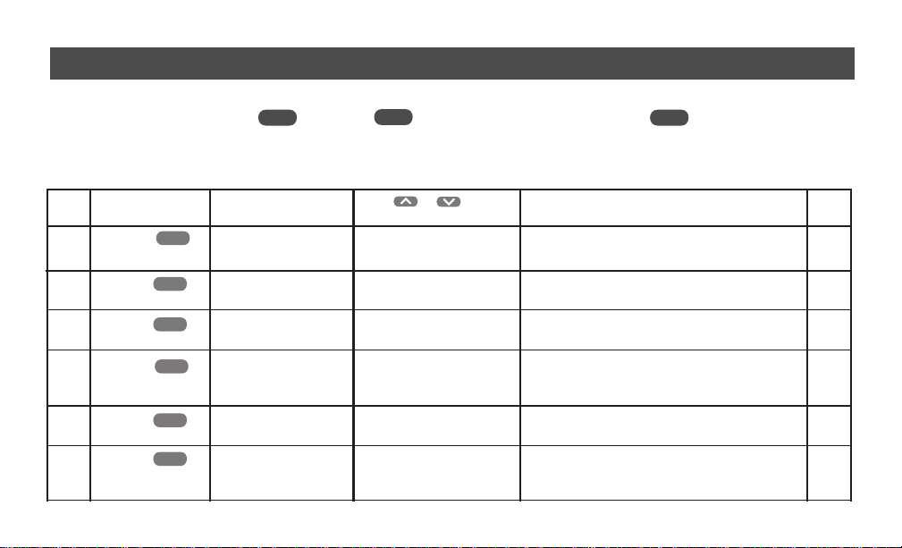
User Configuration Menu
Step Press Button(s) Displayed Press or to select: COMMENTS Ref
(Factory Default) Page
TIME
TIME
TIME
TIME
TIME
TIME
FWD
FWD
FWD
FWD
FWD
FWD
0 °F
(0)
(ON)
(0)
(OFF)
OPTM CMFT
(ON)
(OFF)
1
2 EMR
3 RH
4 DRY
5
6 OPTM DHUM
BACK
once at the same time. Press TIME
5 LO to
Adjusts temperature display higher or lower.
5 HI
OFF ON
Selects EMR option ON or OFF or ON L.
ON L
20 LO to
Adjusts humidity display.
20 HI
LO or HI to OFF
To reduce or eliminate condensation during cold
weather. Use LO setting first, if condensation persists
use HI setting.
OFF
ON
Enables improved dehumidification in cooling mode
if humidity is above setting.
Available if OPTM CMFT is ON. Provides extra
dehumidification if humidity is above setting. May
reduce temperature setpoint by up to 3 degrees.
4
FWD
to advance through the
6
6
7
7
7
8
Page 7
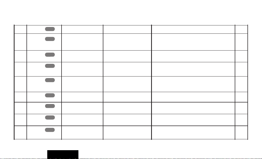
User Configuration Menu (Continued)
7 (°F) °C
8 SET FAN
9
10 HEAT FAST
11 COOL FAST
12
TIME
TIME
TIME
TIME
TIME
TIME
FWD
FWD
FWD
FWD
FWD
FWD
(0)
BEEP
(ON)
(ON)
(OFF)
REMT SEN A
0 HRS (OFF) to
6 HRS
(OFF)
TIME
FWD
REMT SEN B
13
(OFF)
TIME
FWD
REMT SEN C
14
(OFF)
15 STAT SEN L
TIME
FWD
(ON)
Configuration
OFF
OFF
OFF
ON
ON
ON
OFF
Adjusts temperature display between
Set Fan (one shot) option. Set the duration of the
°F or °C
8
8
one shot option.
Turns beeper ON or OFF.
ON allows second stage to energize if setpoint is raised
3 or more degrees. OFF (economy) minimizes second
8
8
stage operation on setpoint changes.
ON allows second stage to energize if setpoint is
lowered 3 or more degrees. OFF (economy) minimizes
9
second stage operation on setpoint changes.
Enables Remote Sensor A (connected to SA).
Enables Remote Sensor B (connected to SA).
Enables Remote Sensor C (connected to SA).
OFF Disables Thermostat Sensor. (Only available if
remote sensor A, B, or C is connected).
9&10
9&10
9&10
9&10
5
Page 8
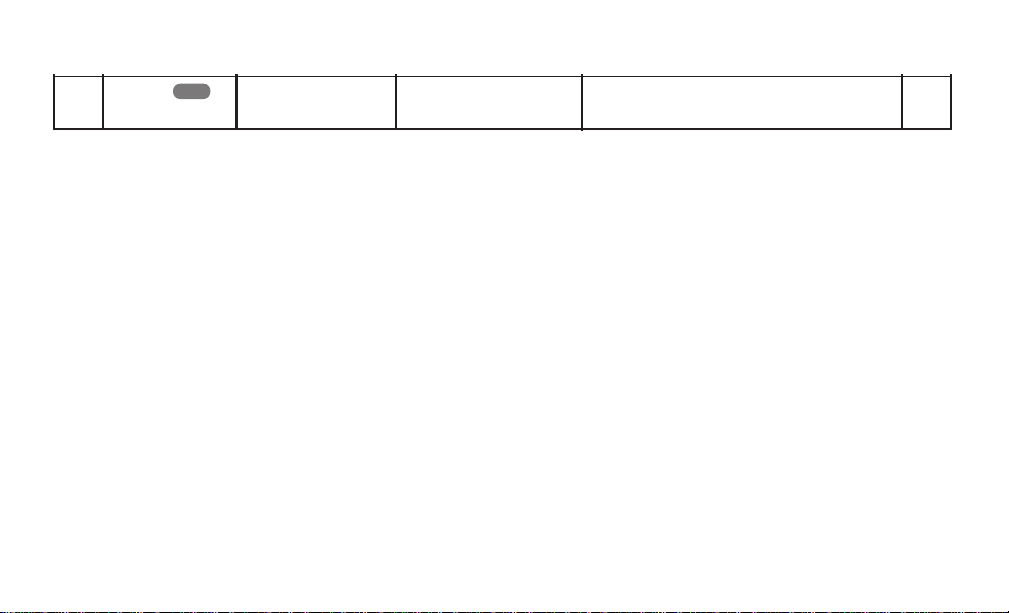
User Configuration Menu (Continued)
TIME
FWD
TEMP OUT
(OFF)
16
ON
Enables outdoor temperature sensor. Requires optional
F145-1378 outdoor sensor.
10
CONFIGURATION MENU
FEATURES
Adjustable Temperature Display.
(User menu, Item 1), The room
temperature display can be adjusted to
read higher or lower by following the
User menu and adjusting the temperature to a higher or lower value. The
thermostat is calibrated at the factory to
display a very accurate room temperature, but due to various conditions and/
or personal preference, you may wish to
adjust the thermostat display higher or
lower (up to 5
°F). For example, if the
thermostat displays a room temperature
of 70
° and you want it to display 73° the
display can be adjusted to read 73
°. To
adjust, refer to the CONFIGURA TION
section (page 5, step 1).
Selectable Energy Management
Recovery (EMR).
(User menu, Step 2) EMR causes the
thermostat to start operating the system
early in order to make the building
temperature reach your program
setpoint at the time you specify. In
multistage heating, the thermostat will
start 8 minutes early for every 1
°F
difference between the room temperature and the next programmed
temperature. In cooling and heat pump
applications, the thermostat uses 15
minutes per
°F. For heating applica-
6
tions in large buildings where extra
time to reach the set temperature may
be desired, EMR Long may be
selected. When EMR ON L is selected
in the user menu (page 5, item 2) the
thermostat uses 15 minutes per
°F.
EXAMPLE: If the temperature in the
room is 65
programmed for 70
°F and the thermostat is
°F at 7 AM, the
thermostat will start approximately 40
minutes early. The difference between the
room temperature (65
(70
°F) is 5° and 5° X 8 minutes per °F =
°F) and the setpoint
40 minutes. The setpoint on the display
will actually change to display 70
° about
40 minutes early. The maximum time the
thermostat can start early in heating is 75
Page 9

minutes (or 3 hours, 45 minutes if EMR
ON L is selected). The maximum time in
cooling and heat pump applications is 3
hours and 45 minutes. Cooling or heat
pump applications start earlier because it
takes longer to reach the desired
temperature. This feature also minimizes
the use of the auxiliary stages if conditions
are such that the compressor stages are
adequate to reach the desired setpoint.
To select or deselect this feature, refer to
the CONFIGURATION section (page 4,
step 2).
Adjustable Humidity Display (RH)
(User Menu step 3) The room
humidity display can be adjusted to
read higher or lower by following the
configuration menu and adjusting the
humidity to a higher or lower value.
The thermostat is calibrated at the
factory to display a very accurate
room humidity, but due to various
Configuration
conditions and/or personal preference,
you may wish to adjust the thermostat
display higher or lower (up to +/20%). For example, if the thermostat
displays room humidity of 40% but
you want it to display 43% you can
adjust it. To adjust, refer to the
CONFIGURATION section
(page 4,
step 3).
Programmable Automatic
Humidity Reduction (DRY)
(User Menu step 4)
This feature automatically lowers
humidity setting when the outside
temperature drops. This is to prevent
the interior windows/walls from
reaching the dew point where water
condenses on surfaces. To achieve
automatic humidity reduction, the
thermostat lowers the humidity when
furnace cycles are long. When the
furnace runs shorter cycles, it increases
7
humidity. For suggested settings see
table below.
Programmable Dehumidification
Optimal Comfort Mode (OPTM
CMFT)
(User Menu step 5)When turned on
this feature automatically reduces
indoor humidity during calls for
cooling if humidity is 2% above
setting. Humidity is set by pressing the
Humidity button when in the appropriate mode, in this case Cooling, and
pressing the
set desired humidity (range 40 to 95)
level followed by pressing Run
Program. This dehumidification
feature uses less energy by maintaining
temperature and dehumidifying only
when a call for Cooling is required.
or buttons to
Page 10

Programmable Dehumidification
Optimal Dehumidification Mode
(OPTM DHUM)
(User Menu step 6)When turned on
this feature automatically reduces
indoor humidity if humidity is 2%
above setting. Humidity is set by
pressing the HUMIDITY button
when in the appropriate mode, in this
case Cooling, and pressing the
or buttons to set desired
humidity level followed by pressing
PROGRAM. This dehumidifi-
RUN
cation feature may use more energy
by making dehumidification a priority
initiating a call for cooling if humidity
is 2% above desired setting. This
feature may also over-cool the
condition space by up to 3 degrees to
achieve the desired humidity level.
Fahrenheit or Celsius
Temperature Display.
(User menu, Step 7) This thermostat
is factory set to display temperature in
Fahrenheit. If you prefer, you may
configure the thermostat to display
Celsius. See the CONFIGURATION
Section, page 4.
Single Period Fan Control.
(User menu, Step 8) This feature
allows you to have the fan run for a
predetermined period of time by
pressing the FAN key twice within 1.5
seconds. If a time is set in the User
menu (page 4, step 8) the display will
show FAN, # hrs and PRG FAN ON
for six seconds. After six seconds the
display will continue to indicate PRG
FAN ON for the time period selected.
After this time period, the fan will
return to normal operation. To return the
8
fan to normal operation before the end of
the time period, press the FAN button.
Beeper on.
(User menu, Step 9) The thermostat
has a beeper that will emit a tone when
any key is pressed. In the user menu, the
BEEP feature can be turned OFF using
or to provide silent key
operation.
Heat Fast.
(User menu, Step 10) This feature,
when set to ON, will bring the second
stage of heating on any time you
manually raise the temperature three or
more degrees above room temperature.
If HEAT FAST is set to OFF, the
thermostat will delay the second stage
from 0 to 30 minutes based on how well
the first stage is keeping up with your
setting.
Page 11

Cool Fast.
(User menu, Step 11) This feature,
when set to ON, will bring the second
stage of cooling on any time you
manually lower the temperature three
or more degrees below room temperature. If COOL FAST is set to OFF,
the thermostat will delay the second
stage from 0 to 30 minutes based on
how well the first stage is keeping up
with your setting.
Optional Remote Temperature
Sense.
(User menu, Step 12,13,14,15) Up to
three remote sensors (F145-1328) can
be attached to this thermostat to sense
indoor temperature at locations away
from the thermostat. Each sensor may
be located as far as 300 feet away from
the thermostat. This is an excellent
feature if the thermostat is in a poor
location for sensing temperature or if
Configuration
you want to install the thermostat in a
separate room to prevent tampering.
After installing and connecting the
remote sensor(s) to the thermostat, the
installer can enable each remote indoor
temperature sensor (A, B, and/or C).
When operating with remote sensor(s),
the thermostat will calculate an
average of the sensed temperatures in
all enabled sensor locations (A, B, C
and/or L), then display the average
temperature as the room temperature.
The temperature at each remote sensor
can be displayed by pressing the light
button twice within one second. With
the thermostat in program run or hold
mode. Temperatures at the outdoor and
indoor remote sensors will be
displayed with subsequent presses of
the light button in the following order
(if connected): outdoor sensor, sensor
L, A, B, C. You can also assign each
sensor different priorities during
9
different program periods. This allows
the system to maintain a comfortable
environment by giving higher priority
to occupied locations. At the same
time, giving lower priority to unoccupied locations enhances efficient
system operation. EXAMPLE: Your
home has bedrooms on the upper level
and a guest bedroom on the main
level, along with the living room,
kitchen, etc. The thermostat (sensor L)
is located in the hall on the main level.
Remote sensors are located on the
upper level (sensor A) and the guest
bedroom (sensor B). The lower level
would be occupied in the DAY
and EVE periods. The upper level
would be occupied in the NHT and
MOR periods. With no guest in the
guest bedroom, the sensors could be
programmed as follows:
Page 12

SENSOR
MOR
DAY
EVE
NHT
L
AVG
HI
HI
AVG
A
HI
AVG
AVG
HI
B
LO
LO
LO
LO
In the MOR and NHT periods, the
sensor on the upper level (sensor A)
has more priority than the lower level
(sensor L), so the system will operate
to keep the temperature at the set point
in the upper level. In the DAY and
EVE periods, the lower level has the
higher priority, so the system will
operate to keep the temperature at the
set point on that level. The sensor in
the guest bedroom has the lower
priority of the sensors. If there is a
guest, the sensor in that room (sensor
B) should be changed to AVG or HI
for periods when that room will be
used. To assign priority to a sensor,
press PROGRAM
VIEW
to advance
the time period you wish to modify,
then press the HUMIDITY button. On
the display in place of period of day
(MOR, DAY, EVE, NHT) the priority
of the sensor and the sensor identification will appear. Press the HUMIDITY button to step through the sensors
that are installed and enabled L (local),
A, B or C. Only sensors that are
installed and enabled will be listed.
When the sensor you wish to change is
displayed, press the DAYLIGHT
SAVING TIME key to change the
priority (AVG , HI or LO). AVG is the
default setting. A setting of HI gives a
sensor more importance and a setting
of LO gives less importance.
Outdoor Temperature Sense.
(User menu, Step 16) A remote sensor
(F145-1378) may be installed for
outdoor temperature measurement.
10
The sensor must be properly connected and enabled using the User
menu. The display shows the outdoor
temperature from -40° to 140°F by
pressing the light button twice within
one second when the thermostat is in
program run or hold mode.
KEYPAD LOCKOUT MENU
The keypad lockout menu allows you
to partially or totally lock out the
keypad depending on your system or
personal requirements. To enter the
keypad lockout menu you must first
enter the User Menu, while in the User
Menu press TIME
the same time for at least one
BACK
second. Press TIME
FWD
FWD
and TIME
to
advance through the menu options.
Page 13
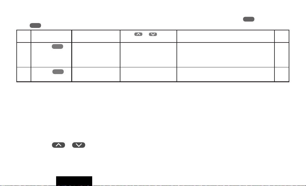
Keypad Lockout Menu (Must be in User Menu to enter Keypad Lock Menu- press and hold Time and
BACK
Time for one second or more).
Step Press Button(s) Displayed Press or to select: COMMENTS Ref
(Factory Default) Page
1
FWD
TIME
2
PART LOCK
(OFF)
LOCK
(OFF)
FWD
TIME
ON
ON
ON Disables all keypad functions except Temp Up and
Down. User may temporary override within
lowest programmed setpoint in cooling and highest
programmed setpoint in heating.
ON Disables all keypad functions.
FWD
10 & 11
10 & 11
Press arrow keys to change options.
Choose one of the two keypad locks to
prevent unauthorized tampering with
the program. Two levels of security are
available, Total Keypad Lockout or
Partial Keypad Lockout. Total
Keypad Lockout renders all buttons
inoperative. Partial Keypad Lockout
allows only the
or
buttons to operate for temporary
temperature overrides. It also limits
the temperature to the maximum
Configuration
heating and minimum cooling
temperatures used in your program.
This is especially useful in buildings
where unscheduled events are
common. Anyone can change the
temperature, but only between the
temperatures you set and only for the
number of hours you specify if you set
up your Hold Till timing (see “Tempo-
rary Program Override” (page 18).
11
Page 14

PROGRAMMING
MANUAL OPERATION
(Bypassing the Program)
Your White-Rodgers 90 Series
thermostat can be used to control
temperature manually (without
programming). For manual operation,
press
COOL, then press PROGRAM
HOLD
temperature as desired.
PROGRAMMED OPERATION
Planning Y our Program
The sample schedule (pages 14 & 15)
shows the factory-installed programs
for heating and cooling. The heating
and cooling programs are separate,
and must be programmed individually.
To use the factory program, set the
clock and press PROGRAM
to select HEAT or
SYSTEM
. Use or to set the
RUN
with the thermostat set to Heat, Cool,
or Auto. Fill out the blank schedules
(pages 16 & 17) with the time and
temperatures you want in your
program. Fill in every space for your
program.The same temperature can be
repeated more than once if you do not
want the temperature to change over
several time periods. This is useful for
homes or businesses that are occupied
all day and only want a setback
temperature at night.
Entering Y our Program
To Set the Clock:
RUN
1. Press PROGRAM
TIME
2. Press SET
. The display will
show the hour. Use TIME
BACK
TIME
to set to the current hour
.
FWD
or
and AM/PM designation.
12
3. Press SET
will show minutes. Use TIME
or TIME
TIME
again. The display
BACK
to set to the current
FWD
minutes.
4. Press PROGRAM
RUN
.
To Set the Day:
DAY
5. Press SET
. The display will
indicate a day of the week. Use TIME
FWD
or TIME
BACK
to set to the
current day of the week.
6. Press PROGRAM
RUN
.
To Set the Program:
7. Press the
SYSTEM
button to select
HEAT (for heating program) or COOL
(for cooling program).
8. Press PROGRAM
VIEW
one time.
The display will show MOR, the
settings for time and temperature and
MON.
Page 15

9. If you program Monday the first
time you press PROGRAM
VIEW
it
will be copied to the rest of the week.
To program the other days of the week
ADV.
press
DAY to until you reach the
day you wish to change and follow
Steps 10, 11 & 12. You can also copy
the program from one day to another.
To copy, press
HOLD
/COPY. The
display will show COPY, and all the
other days of week will be flashing.
HOLD
Press
/COPY again to copy the
day in to the rest of the week or press
TIME
FWD
or TIME
BACK
until you
reach the day you want to copy to and
HOLD
press
10.Press TIME
/COPY.
FWD
or TIME
BACK
to set the time on the display as
selected in your HEATING or
COOLING SCHEDULE. Be sure to
check the AM or PM on the display.
11.Press the
or button to
adjust the temperature to match your
schedule. If you want the fan ON
continuously during this period, press
FAN
the
12.Press PROGRAM
button.
VIEW
MOR on the display will change to
DA Y. Repeat steps 10 and 11 to enter
time and temperature for this period.
13.Press PROGRAM
VIEW
continue through the entire schedule,
entering time and temperature for each
period. When you are satisfied that
your program matches your schedule,
press PROGRAM
RUN
ming is now complete for this mode
and your program is running.
14.To program the other mode, repeat
the procedure from step 6.
13
Programming
one time.
to
. Program-
Page 16

7-Day Sample HEAT Program Schedule
(Shows factory programming)
MON
TUE
WED
THU
FRI
SAT
SUN
1
Morning (MOR)
2
Day (DAY)
3
Evening (EVE)
4
Night (NHT)
5
Start Time
6
Temperature
6:00 AM 70°F (21°C) 8:00 AM 70°F (21°C)
6:00 AM 70°F (21°C) 8:00 AM 70°F (21°C)
6:00 AM 70°F (21°C) 8:00 AM 70°F (21°C)
6:00 AM 70°F (21°C) 8:00 AM 70°F (21°C)
6:00 AM 70°F (21°C) 8:00 AM 70°F (21°C)
6:00 AM 70°F (21°C) 8:00 AM 70°F (21°C)
6:00 AM 70°F (21°C) 8:00 AM 70°F (21°C)
1
2 3 4
5 6 5 6 5 6 5 6
62°F (16°C)
62°F (16°C)
62°F (16°C)
62°F (16°C)
62°F (16°C)
62°F (16°C)
62°F (16°C)
14
5:00 PM 10:00 PM
5:00 PM
5:00 PM
5:00 PM
5:00 PM
5:00 PM
5:00 PM
10:00 PM
10:00 PM
10:00 PM
10:00 PM
10:00 PM
10:00 PM
62°F (16°C)
62°F (16°C)
62°F (16°C)
62°F (16°C)
62°F (16°C)
62°F (16°C)
62°F (16°C)
Page 17

7-Day Sample COOL Program Schedule
(Shows factory programming)
MON
TUE
WED
THU
FRI
SAT
SUN
1
Morning (MOR)
2
Day (DAY)
3
Evening (EVE)
4
Night (NHT)
5
Start Time
6
Temperature
6:00 AM 78°F (25°C) 8:00 AM 78°F (25°C)
6:00 AM 78°F (25°C) 8:00 AM 78°F (25°C)
6:00 AM 78°F (25°C) 8:00 AM 78°F (25°C)
6:00 AM 78°F (25°C) 8:00 AM 78°F (25°C)
6:00 AM 78°F (25°C) 8:00 AM 78°F (25°C)
6:00 AM 78°F (25°C) 8:00 AM 78°F (25°C)
6:00 AM 78°F (25°C) 8:00 AM 78°F (25°C)
1
2 3 4
5 6 5 6 5 6 5 6
85°F (29°C)
85°F (29°C)
85°F (29°C)
85°F (29°C)
85°F (29°C)
85°F (29°C)
85°F (29°C)
15
5:00 PM 10:00 PM
5:00 PM
5:00 PM
5:00 PM
5:00 PM
5:00 PM
5:00 PM
10:00 PM
10:00 PM
10:00 PM
10:00 PM
10:00 PM
10:00 PM
82°F (27°C)
82°F (27°C)
82°F (27°C)
82°F (27°C)
82°F (27°C)
82°F (27°C)
82°F (27°C)
Programming
Page 18

7-Day Personal HEAT
Program Schedule
MON
TUE
WED
THU
FRI
SAT
SUN
1
Morning (MOR)
2
Day (DAY)
3
Evening (EVE)
4
Night (NHT)
5
Start Time
6
Temperature
1
2 3 4
5 6 5 6 5 6 5 6
16
Page 19

7-Day Personal COOL
Program Schedule
MON
TUE
WED
THU
FRI
SAT
SUN
1
Morning (MOR)
2
Day (DAY)
3
Evening (EVE)
4
Night (NHT)
5
Start Time
6
Temperature
1
2 3 4
5 6 5 6 5 6 5 6
17
Programming
Page 20

FEATURES
Pushbutton Backlight
The large numbers and letters on your
LCD screen make it easy to see. In low
light conditions, press the button on
top of the thermostat and the display
will light up for three seconds. For ten
minutes after pressing the light button,
pressing any other button will light the
display for ten seconds.
Factory Preprogramming
This thermostat has been programmed
at the factory. The chart in the
programming examples section lists
these factory settings. If the times and
temperatures are the same as your
schedule, you may simply run the
factory installed program by pressing
PROGRAM
RUN
.
Temporary Program Override
Any time your program is running and
you would like to override it for a
specific amount of time, press
or until the temperature you
want is displayed. The display will
indicate HOLD, and the number of
hours remaining in the hold period is
indicated with the word HRS. To
adjust the length of time for the
override, press TIME
. HOLD TILL will be displayed
BACK
FWD
or TIME
as well as the HOLD period expiration
time. Press TIME
buttons until you reach the time
BACK
FWD
or TIME
you would like it to resume the
program. The TIME
buttons adjust the time in 15
BACK
FWD
or TIME
minute increments. This programmed hold time has a 19 hour
18
maximum and 15-minute minimum.
Beyond 19 hours you may wish to use
the vacation hold feature (pages 19 &
20). If you need to, you can adjust the
temperature up or down.
Indefinite Program Hold.
If you want to operate the thermostat to
keep a set temperature without a
program running, press PROGRAM
. The temperature Up or Down
HOLD
buttons can be used to raise or lower
the temperature. The thermostat will
hold the set temperature until you
return to the program by pressing
PROGRAM
RUN
.
Page 21

Automatic Heat/Cool
Changeover
If you have a heating/cooling system,
the thermostat can be set to automatically switch the system from heating to
cooling as needed. To set your
thermostat to this operating mode,
press the
button until AUTO
SYSTEM
is displayed on the screen. To change
the mode of operation from heating or
cooling can be accomplished by
pressing the
and buttons
at the same time, this will change the
setpoint temperature displayed to the
setpoint of the other mode. This will
allow you to modify both the HEAT
and COOL setpoints to accommodate
a HOLD condition while in Automatic
Changeover mode. Note: For proper
Automatic Changeover mode the
heating setpoint must be at least 1°F
lower than the cooling setpoint in each
program period. If the heating setpoint
is equal to or higher than the cooling
setpoint this causes is conflict. The
thermostat will indicate a conflict by
flashing the setpoint and will resolve
the conflict by choosing a heating
setpoint that
is an average of the two program
setpoints. The cooling setpoint will
be two degrees higher than the heating
setpoint.
Adjustable T emperature Display
The room temperature display can be
adjusted to read higher or lower by
following the configuration menu and
adjusting the temperature to a higher
or lower value. The thermostat is
calibrated at the factory to display a
very accurate room temperature, but
due to various conditions and/or
personal preference, you may wish to
adjust the thermostat display higher or
lower (up to 5°F). For example, if the
19
Features
thermostat displays a room temperature of 70° but you want it to display
73°, you can adjust it. To adjust, refer
to the USER CONFIGURATION
section (page 4, step 1).
Programmable Fan Control
This feature allows you to have your
fan operate continuously through one
or more programmed time periods.
This is useful if you want constant air
circulation in your location during a
specific time period. If you do not use
this feature, the fan will cycle normally
with the heating and cooling system.
Programmable V acation Time/
Temperature Operation.
The VACATION mode allows you to
program the thermostat to hold a
constant temperature for 1 to 29 days.
At the end of the day and time you
select, the thermostat will return to
Page 22

normal program operation. To program
the number of days, press the
or
to set your temperature then
press and release the SET
DAY
button and VACA HOLD TILL will be
displayed. The display will also show
DAYS (flashing) and the number 5. To
change the number of vacation days,
press TIME
Press
or TIME
FWD
or to set the
BACK
.
temperature you wish to maintain
while away. While still in the vacation
mode, set the time you require your
program to resume by pressing SET
once. The current time will
TIME
display along with the word HRS
(flashing). Press TIME
FWD
to adjust
the time in 15 minute increments. You
may wish to select a few hours in
advance of your expected return to
allow time to reach the desired
temperature. Your thermostat is now
programmed to hold the temperature
you selected through your vacation for
HEAT, COOL, or AUTO. After 20
seconds the display will return to time/
temperature alternation, and will
display VACA. Pressing PROGRAM
cancels this feature and begins
RUN
running your normal program.
Keypad Lockout.
This security feature allows you to lock
out the keypad to prevent unauthorized
tampering with the program. Two
levels of security are available, Total
Keypad Lockout or Partial Keypad
Lockout. Total Keypad Lockout
renders all buttons inoperative. Partial
Keypad Lockout allows only the
or to operate for temporary
temperature overrides. It also limits the
temperature to the maximum heating
and minimum cooling temperatures
used in your program. This is
20
especially useful in buildings where
unscheduled events are common.
Anyone can change the temperature,
but only between the temperatures you
set and only for four hours or the
number of hours you specify if you set
up your Hold Till timing (see
Temporary Program Override, page
18). To select or deselect this feature,
refer to the USER CONFIGURA TION
section (page 11, steps 1 and 2).
Thermostat Startup Up
After Power Loss.
The user program and installation and
configuration settings are stored in
permanent memory indefinitely . After
a total power loss of 24V to the
thermostat for more than 4 hours the
clock and day settings will be lost.
When power is restored your thermostat will maintain a heating temperature of 62°F and a cooling temperature
Page 23

of 85°F. If this happens, set the clock
and day of the week (using steps 1
through 6 from “Entering Your
Program”, page 12 & 13), then select
HEAT, COOL or AUTO using the
button, and press PRO-
SYSTEM
GRAM
to resume operation
RUN
with your previously set program.
Compressor
Short Cycle Protection.
Your thermostat can be configured to
protect your system against premature
compressor failure by “locking out”
the compressor. This ensures that the
compressor will stay off for at least
five minutes on each cycle. When the
thermostat is in compressor lock-out,
the word COOL will flash. During this
period, the compressor will not be
energized. See the installation
instructions.
Service Button Menu
The Service button allows setting of
maintenance reminders for three
optional equipment accessories
typically used with forced air heating/
cooling systems. The three accessories
humidifier, air filter, and UV light are
designed to enhance indoor air quality.
A humidifier will add humidity when
conditions would normally make the
indoor air uncomfortably dry. Air
filters are designed to clean the air
through a forced air system. These
accessories require routine maintenance to provide optimum performance. The service button maintenance reminders are designed so that
they can be customized to the
requirements of each accessory. If your
system is a forced air system you may
have none or all three accessories. The
fourth maintenance reminder is for
routine servicing of your system by a
21
Features
professional HVAC contractor. The
fourth reminder option may be used in
lieu of or in conjunction with the other
reminders. If you’d prefer having a
professional service your system, the
Routine Maintenance Reminder is the
only reminder you’ll need to set. To
disable a feature that was previously
selected, press TIME
BACK
button to
show either REM PAD TIME, REM
FLTR TIME, REM UV TIME, or
REM SERV TIME and then press the
or arrow to turn OFF.
Page 24

Service Button Menu
Step Press Button(s) Displayed Press or to select: COMMENTS
(Factory Default)
1
2
3
4 SET FLTR TIME
5
6
SERVICE
FWD
TIME
(If PAD TIME is ON)
FWD
TIME
FWD
TIME
(If FL TR TIME is ON)
FWD
TIME
FWD
TIME
(If UV TIME is ON)
P AD TIME
(OFF) Hrs
or
REM PAD TIME
No. of Hrs
SET PAD TIME
(100) Hrs
FL TR TIME
(OFF) /Hrs
or
REM FLTR TIME
No. of Hrs
(200) Hrs
UV TIME
(OFF) Days
or
REM UV TIME
No. of Days
SET UV TIME
(375) Days
(ON)
or
(OFF)
25 to 1975
(ON)
or
(OFF)
25 to 1975
(ON)
or
(OFF)
25 to 1975
22
Set Humidifier Maintenance Reminder.
Selects time intervals in increments of 25 hours. The RUN
time accumulates when the HM terminal is energized.
Set Air Filter Maintenance Reminder.
Selects time intervals in increments of 25 hours.
The RUN time accumulates when the fan is operating.
Selects UV Light Maintenance Reminder.
Selects time intervals in increments of 25 days. The RUN
time is the calendar time from when it is entered or reset.
Page 25

Service Button Menu (Continued)
TIME
7
TIME
8
(If SERV TIME is ON)
PRGM
FWD
FWD
RUN
SERV TIME
(OFF) Days
or
REM SERV TIME
No. of Days
SET SERV TIME
(175) Days
(ON)
or
(OFF)
25 to 1975
Selects Routine Maintenance Service Call Reminder.
Selects time intervals in increments of 25 days. The RUN
time is the calendar time from when it is entered or reset.
Returns to Normal Operation.
Humidifier
Maintenance Indicator.
This feature allows the thermostat to
display the words CHCK PAD (check
humidifier) after a set time of
humidifier operation. This is a
reminder to maintain or clean your
humidifier. The factory set interval for
CHCK PAD to be displayed is 100
hours of humidifier operation. This
should be adjusted with respect to the
humidifier’s recommended maintenance schedule.
Air Filter
Change-Out Indicator.
This feature allows the thermostat to
display the words CHNG FLTR
(change filter) after a set time of fan
operation. This is a reminder to change
or clean your air filter. The factory set
interval for CHNG FLTR to be
displayed is 200 hours of fan operation. This can be set anywhere from 0
to 1975 hours in 25 hour increments. A
selection of OFF will cancel this
feature. When CHNG FLTR is
23
Features
displayed, you can clear it by pressing
the SERVICE button. This resets
the timer and starts counting the hours
until the next filter change. The
following steps will allow you to
change the number of hours for filter
change-out.
1. If you see CHNG FLTR on the
display, press the SERVICE button
once to reset the timer. If you do not
see CHNG FLTR proceed to step 2.
When the SERVICE button is pressed
twice, the display will show the The
Page 26

number of hours remaining before
CHNG FLTR indicator will display.
2. Press the SERVICE button. The
display will show SET FILTER TIME
and will show the number of hours to
filter change.
3. Press TIME
FWD
or TIME
BACK
to change the time to your requirements.
4. Press PROGRAM
RUN
to return
to the normal operating mode. NOTE:
If unsure what interval to use between
filter changes or cleaning, contact the
manufacturer of your heating/cooling
equipment.
UV Bulb Replacement Indicator.
This feature allows the thermostat to
display the words CALL SERV UV
(Call for Service of UV bulb) after a
set time of UV bulb operation. This is
a reminder to maintain your UV system
at optimum level of operation. When
enabled the factory set interval for
CALL SERV UV to be displayed is
350 days of UV bulb operation and
can be adjusted in 25 day increments.
This should be adjusted with respect to
the bulb’s recommended maintenance
schedule.
Routine Maintenance Reminder.
This feature allows the thermostat to
display the words CALL SERV (Call
for Service) after a set time of system
operation. This is a reminder to
maintain your system at optimum
level of operation. The factory set
interval for CALL SERV to be
displayed is days of system operation.
This should be adjusted with respect to
your HVAC service company’s
recommendation. When enabled the
default is 175 days and can be adjusted
in 25 day increments.
24
System and
Thermostat Diagnostics.
The display will indicate CHECK
SYSTEM if the room temperature
does not rise within two hours of the
call for heat. After two hours the
thermostat will quit calling for heat for
one minute (this allows some furnaces
to reset) and call for heat again. When
CHCK PAD is displayed, you can
clear it by pressing SERVICE button.
This resets the timer and starts
counting the hours until the next
humidifier maintenance. The following
steps will allow you to change the
number of hours for humidifier
maintenance.
1. If you see CHCK PAD on the
display, press the SERVICE button
once to reset the timer. Press SER-
VICE button again the display will
show the number of hours to humidifier maintenance.
Page 27

2. Press TIME
FWD
or TIME
BACK
to change the time to your requirements.
3. Press PROGRAM
RUN
to return
to the normal operating mode. If the
temperature still does not rise, it will
continue to call for heat. This normally
indicates the heating system is not
working correctly. You may wish to
consult your furnace manufacturer or
service person. The display will
indicate CHECK STAT if one of the
following occurs.
• One of the buttons is stuck down or
in. Check buttons, make sure nothing
is pushing them in.
• The thermostat sensor is not
functioning. If using a remote sensor,
check connections, wiring and power.
• The humidity sensor is not functioning. After checking the above, press
PROGRAM
to reset the
RUN
display. If this does not clear the
display, disconnect power for five
minutes. If these checks fail to solve
the problem, the thermostat should be
replaced.
Adjustable Humidity Display.
The room humidity display can be
adjusted to read higher or lower by
following the configuration menu and
adjusting the humidity to a higher or
lower value (up to 20% RH). The
sensed humidity is calibrated at the
factory. If you want to adjust it, refer
to the CONFIGURATION section
(page 4, step 3).
Programmable Automatic
Humidity Reduction.
This feature automatically lowers
humidity when the outside temperature
drops. This is to prevent the interior
windows/walls from reaching the dew
point where water condenses on
surfaces. To achieve automatic
25
Features
humidity reduction, the thermostat
lowers the humidity when furnace
cycles are long. When the furnace runs
shorter cycles, it increases humidity.
For suggested settings see table below.
Factory default — no humidity
OFF
reduction.
W ell insulated homes requiring
LO
little humidity reduction.
Poorly insulated homes or homes
HI
with a lot of condensation on
windows/walls.
If your window insulation is poor, you
need high humidity reduction. If your
window insulation is good, you need
low humidity reduction (factory
setting). Selection of OFF will cancel
this feature. To adjust this feature,
refer to the CONFIGURATION
section (page 4, step 4).
Page 28

Humidifier Control
and Monitoring
When the humidity button is pressed
while in the run mode and in the HEAT
position, the actual humidity will be
displayed on the left side of the
display. HUMD is displayed above
the actual humidity. The humidity set
point is displayed on the right side of
the display.
or button
may be pressed to modify the humidity
set point (range 5 to 50). Maximum
displayed humidity is 97% RH and
minimum displayed humidity is 2%
RH. If the heating system is operating
and there is a demand for humidity,
then the humidifier will operate. If the
demand for humidity is not satisfied
for ten consecutive heat cycle
operations, the display will show the
word HUMD for one second and the
word MX for one second signaling
maximum possible humidity is
reached.
FAQs
1. My thermostat is reading
Celsius. How do I change it
to Fahrenheit?
2. How do I bypass (not
use) the program?
1F95-391
Press TIME
TIME
FWD
PROGRAM
Press PROGRAM
to bypass the program and operate the thermostat manually press the MODE
to select Heat or Cool (whichever you prefer) and press
TEMP
setting you choose will be held until you manually change it using the TEMP
TEMP
temperature and maintain whatever temperature you set. If you decide to return to the
program, press PROGRAM
FWD
and TIME
at the same time to enter the configuration menu. Press
BACK
until you get to °C then press the or arrow to select °F, press
to return to normal operation.
RUN
to make certain the thermostat is in the run program mode, then
RUN
SYSTEM
. Use the TEMP or
HOLD
buttons to set the thermostat on the temperature you want. The temperature
buttons. The thermostat will remain in the HOLD mode when you change
to cancel the hold feature.
RUN
26
button
or
Page 29

FAQs
1F95-391
3. My furnace (air conditioning) cycles too fast
(slow). Is there an adjustment?
4. Why does the blower fan
keep running after the
system has shut off?
The 1F95-391 has a feature called Adjustable Heating and Cooling Cycle times (also called
Anticipation) that allows you to increase or decrease the cycle times in heating and cooling.
This is useful if you think your cycle times are too long or too short. The higher the number
you select, the longer the cycle. The lower the number you select, the shorter the cycle. The
1F95-391 is adjusted in the Installer Table (see your installation instructions). The range of
adjustment for HEATING is from 1 to 40. The factory Preset is 05, the range of adjustment
for COOLING is from 9 to 40. The factory Preset is 24. The cooling will not go below 9
because compressors require a longer cycle. See page 6 of your Installation Instructions.
Normally the blower will turn off within a few minutes after the call for heat or cool. The
blower running after the system shuts off may indicate (1) the thermostat is set to FAN ON,
(2) the fan has been programmed to run at that time period or (3) something has damaged the
thermostat or equipment. If the thermostat display indicates FAN ON, press the fan button
once to set it to FAN AUTO, meaning the fan will cycle only with the equipment. If the
display indicates PRG FAN (Program Fan), sometime during programming, the
FAN
button was pushed. To remove PRG FAN (Program Fan), check all of the programmed
times and temperatures. When you encounter PRG FAN, press the
FAN
button to
remove it from that time period in the program. As a final test, set the thermostat to OFF.
Verify that FAN ON or FAN AUTO is not displayed. If the fan continues to run, you may
want to contact your heating and cooling service person for assistance.
27
FAQs
Page 30

FAQs
1F95-391
5. Do I have to program a
stop time for each program
period?
6. My display light does not
work. Can it be fixed or
replaced?
7. Between Heating and
Cooling seasons, I want to
turn my system off. Will this
change the program?
8. Do I have to reprogram
my thermostat after a power
outage?
9. How can I get an extra
copy of the Operating
Manual for my thermostat?
There is no need to select a time to stop a programming period. Starting a new programming
period will stop the previous program period.
The display light in the 1F95-391 is not a replaceable item.
Any time you wish to turn your system off, simply press
button until the display
SYSTEM
shows OFF. This will not affect your thermostat’s programming in any way. To turn the
system back on, press
press
. The system will begin operating according to the current thermostat program.
RUN
button until HEAT, OFF, COOL, or AUTO is displayed and
SYSTEM
The 1F95-391 will retain the last program entered indefinitely without power.
Visit our website at www.white-rodgers.com for operating manuals.
28
Page 31

FAQs
1F95-391
10. What do I do if my
system is not working
properly and I need service?
11. What does CHCK PAD
on the display mean and
how do I reset it?
12.When I push the
Humidity button, the
display shows HUMD MX.
What does this mean?
13.Why does the system run
with the setpoint and room
temperature the same?
Contact a Local Heating & Cooling service person or visit our website at
www.white-rodgers.com to consult our “Where to Buy” Service/Dealer locator.
This feature displays the words CHCK PAD (check humidifier) after a set time of humidifier
operation. This is a reminder to maintain or clean your humidifier. When CHCK PAD is
displayed, you can clear it by pressing the SERVICE button.
HUMD MX indicates the humidifier has not reached the current humidity setting in the last
10 heating cycles. If the condition persists, a service person may recommend additional
humidifier capacity.
In cooling, as the room temperature falls you will eventually reach the setpoint temperature.
The system will continue to run until it reaches the low side of the temperature setting. As
an example: If set to 78 degrees with the room temperature falling the thermostat will
continue to call for cool as the temperature decreases in the following manner. 78.9, 78.8,
78.7, 78.6, 78.5, 78.4, 78.3, 78.2, at approximately 78.2 the thermostat will quit calling for
cool. This is why it is not unusual for the room temperature and set temperature to read the
same but the system continues to run. The amount of time it takes for the system to shut off
29
FAQs
Page 32

1F95-391FAQs
(cont.)
13.Why does the system run
with the setpoint and room
temperature the same?
14. How do I reset my
thermostat?
is dependent on system sizing, thermostat location, etc. Note: The thermostat display only
displays whole numbers. Internally the thermostat calculates decimals.
In heating as the room temperature increases the system will continue to run until the
thermostat reaches the high side of the temperature setpoint.
There are 3 possibilities to consider, excluding tampering.
1. Loss of power from the system, 24VAC should be constant to maintain a display.
2. Static electricity or a voltage spike from the heating equipment might be resetting the
thermostat. Static electricity can be eliminated by touching something before touching the
thermostat to dissipate the static charge. A voltage spike from the equipment can be
eliminated using an isolation relay as described in the link below.
http:www.white-rodgers.com/pdfs/instruction_sheets/0037_5426_A.pdf
You can also check the wire routing to verify the thermostat or remote wires are not running
parallel to high voltage lines with high inductive loads which could (in extreme cases)
create a voltage spike at the thermostat.
3. Thermostat not functioning properly. A simple test would be to bench test one of the units
for a couple of days to see if it resets or move it to another system where a reset has never
occurred.
30
Page 33

1F95-391FAQs
15. How do I temporarily
Override the program and
Hold Til Timing?
16. What is the
thermostat Click Test?
Any time your program is running and you would like to override it for a specific amount
of time, press
indicate HOLD, and the number of hours remaining in the hold period will be indicated
with the word HRS. To adjust the length of time for the override, press TIME FWD or
TIME BACK. The time you select will become the new number of hours for the Hold Til
timing. Once your time is selected, let the thermostat revert back to normal operation on its
own to accept the change.
Many furnaces have safety devices that shut the system down when a lock-out condition
occurs in the furnace. If the thermostat is turned off or the call for heat is cancelled (by
lowering and then raising the set temperature) the furnace may start operating again. A
diagnostic to see if the thermostat is operating when the room temperature is below the
thermostat setting (in heat) is to lower the setting below the room temp. Within about 3
seconds the thermostat should make a soft click sound. This sound is the thermostat turning
off the call for heat and usually indicates the thermostat is operating properly. If the
thermostat does not click you would be suspicious of the thermostat and try resetting it by
following it’s reset operation. If the thermostat does not click after being reset contact your
heating and cooling service person or place of purchase for a replacement. If the thermostat
clicks and the heat works intermittently contact the furnace manufacturer or local service
person. They will want to observe the condition when it is not working.
or until the temperature you want is displayed. The display will
31
FAQs
Page 34

1F95-391FAQs
(cont.)
16. What is the thermostat
Click Test?
17. What do AUX,
EMER, and MALF
indicators mean on a
heat pump thermostat?
You can raise and lower the temperature a few degrees above and below the room temperature and each time expect to hear the thermostat click on and off within a few seconds. If it
clicks, it is operating properly.
Aux. = Auxiliary Heat or the second stage of heat in the Heat mode. This is energized
when the Heat Pump is not keeping up with the thermostat setting. It is normal operation
with most pumps for the thermostat to call for auxiliary heat.
Emer. = Emergency Heat. When switched to Emergency the thermostat bypasses the pump
and uses the back-up heat. This is useful if the pump is not operating correctly or if the
temperature outside is so cold that the pump is not economical to run.
Malf. = Malfunction. Malfunction indicates the heat pump system is sending a signal to the
Malfunction Light on the thermostat terminal marked “L”. It does not indicate a malfunction in the thermostat. The manufacturer of the Heat Pump system can determine the likely
cause of malfunction indication on the thermostat.
In many heat pump systems Emergency and Auxiliary heat are the same source. If you
switch the thermostat to Emergency it will bypass the heat pump and bring on the back-up
heat. If you leave the thermostat in the Heat mode it will call for Auxiliary when the pump
is not keeping up with your setpoint temperature. Emergency is energized on a call for heat
in the Emergency heat mode.
32
Page 35

TROUBLESHOOTING
RESETTING THERMOST A T
The thermostat can be reset back to factory default programs and configuration options. Removing power from the thermostat will
not reset it to the default settings. Before resetting the thermostat you may want to make note of the previously selected configura-
tion options and programming.
To reset the thermostat, press and release PROGRAM
, then press the
RUN
FAN
, TIME
and buttons at the
BACK
same time. This will reset the thermostat to factory default programs and configuration. The display will momentarily go
blank, and then all segments on the display will momentarily be shown. The thermostat will then go into the AUTO HOLD
mode and will maintain a factory preset temperatures of 62°F in Heat or 85°F in Cool. To clear the HOLD TEMPERA-
TURE overide press the PROGRAM
SYMPTOM
No Heat/No Cool/No Fan
(common problems)
POSSIBLE CAUSE
1. Blown fuse or tripped circuit
breaker.
2. Furnace power switch to OFF.
3. Furnace blower compartment
door or panel loose or not properly
RUN
button.
CORRECTIVE ACTION
Replace fuse or reset breaker.
Turn switch to ON.
Replace door panel in proper position to engage
safety interlock or door switch.
installed.
33
Troubleshooting
Index
Page 36

SYMPTOM
No Heat (Heat may also be
intermittent.)
POSSIBLE CAUSE
1. Pilot light not lit.
2. Thermostat not set to Heat.
3. Loose connection to thermostat or
system.
4. Furnace Lock-Out Condition.
CORRECTIVE ACTION
Re-light pilot.
Press the
button until Heat is displayed and
SYSTEM
raise temperature above room temperature.
Verify thermostat and system wires are securely
attached.
Many furnaces have safety devices that shut down
when a lock-out condition occurs. If the heat works
intermittently, contact the furnace manufacturer or
local service person for assistance.
No Cool
1. Thermostat not set to Cool.
2. Loose connection to thermostat or
system.
3. Cooling system requires service or
thermostat requires replacement.
34
Press the
button to Cool and lower tempera-
SYSTEM
ture below room temperature.
Verify thermostat and system wires are securely
attached.
Press the
button until Cool is displayed and
SYSTEM
lower setpoint below room temperature.
There may be five minute delay before the
thermostat clicks in cooling.
Page 37

SYMPTOM
POSSIBLE CAUSE
CORRECTIVE ACTION
Heat, Cool or Fan Runs
Constantly
1. Possible short in wiring.
2. Possible short in thermostat.
3. Possible short in heat/cool/fan
system.
4. Fan Switch is set to Fan On.
35
Check each wire connection to verify they are not
shorted or touching together. No bare wire should
stick out from under terminal screws.
Try resetting the thermostat as described on page 31.
If the FAN button is pressed to display ON, the
blower fan will cycle continuously whether the
heating or cooling system is running, press the FAN
button until AUTO is displayed. If the condition
persists, the manufacturer of your system or service
person can instruct you on how to test the Heat/Cool
system for correct operation. If the system operates
correctly, replace the thermostat.
Troubleshooting
Page 38

SYMPTOM
INDEX
Furnace Cycles Too Fast or
Too Slow (narrow or wide
temperature swing)
POSSIBLE CAUSE
1. The location of the thermostat
and/or the size of the Heating System
may be influencing the cycle rate.
CORRECTIVE ACTION
Digital thermostats normally provide precise
temperature control and may cycle faster than some
older mechanical models. A faster cycle rate means
the unit turns on or off more frequently but runs for
a shorter time so there is no increase in energy use.
If you would like to increase the cycle time, refer to
the Installation Instructions under Installer Table for
settings. If an acceptable cycle rate is not achieved
by the adjustment in the Installer Table then you
may want to contact a local heating and air conditioning service person for further suggestions.
Cooling Cycles Too Fast or
Too Slow (narrow or wide
temperature swing)
1. The location of the thermostat
and/or size of the Cooling System
can influence the rate.
36
The cycle rate for cooling is fixed and can not be
adjusted. Contact a local service person for suggestions.
Page 39

SYMPTOM
INDEX
Thermostat Setting and
Thermostat Thermometer
Disagree
POSSIBLE CAUSE
1. Thermostat thermometer setting
requires adjustment.
CORRECTIVE ACTION
The thermostat can be adjusted +/- 5°F. See the
Temperature Display Adjustment in the Operating
Manual under configuration.
Thermostat Does Not Follow
Program
Blank Display and/or Keypad
Not Responding
1. AM or PM set incorrectly in
program.
2.AM or PM set incorrectly on the
clock.
3. Voltage spike or static discharge.
1. Voltage spike or static discharge.
37
Check current clock and program settings including
the AM or PM designations for each time period. If a
voltage spike or a static discharge occurs use the
Reset Operation listed above.
Check heat/cool system for proper operation. If a
voltage spike occurs, use the Reset Operation by
pressing FAN, TIME
, and the temperature
BACK
arrow at the same time.
Troubleshooting
Page 40

INDEX
Adjustable Humidity Display ------- 25
Adjustable Temperature Display --- 19
Air Filter Change-Out Indicator ---- 23
Automatic Heat/Cool Changeover - 19
Compressor Short-Cycle
Protection -------------------------- 21
CONFIGURATION -------------------- 4
Configuration Menu Chart ------------ 4
Factory Preprogramming ------------ 18
FAQs ----------------------------------- 26
FEATURES --------------------------- 18
Humidifier Maintenance Indicator - 23
Humidifier Control and Monitoring 26
Indefinite Program Hold
(Bypassing the Program) -------- 18
INTRODUCTION --------------------- 3
Thermostat Buttons----------------- 1
(LCD) Display ---------------------- 2
Keypad Lockout ---------------------- 20
Operation
Manual ----------------------------- 12
Programmed ----------------------- 12
Program
Entering Your---------------------- 12
Planning Your --------------------- 12
PROGRAMMING ------------------- 12
Programmable Automatic Humidity
Reduction -------------------------- 25
Programmable Fan Control --------- 19
Programmable Vacation Time/Temp 19
Pushbutton Backlight ---------------- 18
Schedule
Sample Programs ----------------- 14
Personal Programs ---------------- 16
38
Selectable Energy Management
Recovery (EMR)-------------------- 6
Set
Clock ------------------------------- 12
Day --------------------------------- 12
Program ---------------------------- 12
System and Thermostat
Diagnostics ------------------------ 24
Temporary Program Override------- 18
Thermostat Startup After Total
Power Loss ------------------------ 20
TROUBLESHOOTING ------------- 32
Page 41

NOTES
39
Page 42

The Emerson logo is a
trademark and service mark
of Emerson Electric Co.
White-Rodgers is a division
of Emerson Electric Co.
40
PART NO. 37-6528B
Replaces 37-6528A
0443
 Loading...