

Page 1
Installation Instructions for
Digital Heating & Cooling
Model 700
Non-Programmable Thermostat
CONTENTS
Preparations.................................................. 1
Thermostat Details ........................................ 1
Removing Old Thermostat ............................ 1
Mounting and Wiring ..................................... 2
Check Thermostat Operation........................ 3
Specifications ................................................ 5
Troubleshooting ............................................ 5
Y OUR THERMOST AT REPLACES
Description 700
Standard Heat & Cooling Systems – 4 or 5 wires Yes
Standard Heat Only Systems Yes
Millivolt Heat Only Systems – Floor or Wall Furnaces Yes
Standard Central Air Conditioning Yes
Gas or Oil Heat Yes
Electric Furnace Yes
Hydronic (Hot Water) Zone Heat – 2 Wires Yes
Hydronic (Hot Water) Zone Heat – 3 Wires No
Heat Pump (No Aux or Emergency Heat) Yes
Heat Pump (with Aux or Emergency Heat) No
Baseboard Electric Heating or Line Voltage (120 or 240 volt) No
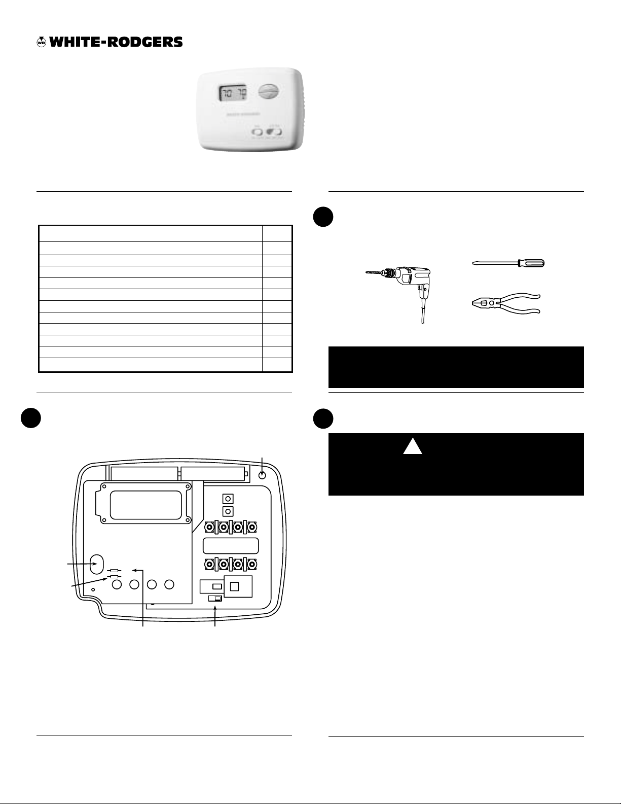
THERMOSTAT DETAILS
2
-
-
+
Mounting
hole
+
PREPARATIONS
1
Assemble tools required as shown below.
FLAT BLADE SCREWDRIVER
HAND OR POWER
DRILL WITH 3/16 INCH
DRILL BIT, IF NEEDED
WIRE CUTTER/STRIPPER
Failure to follow and read all instructions carefully
before installing or operating this control could cause
personal injury and/or property damage
REMOVING OLD THERMOSTAT
3
CAUTION
!
To prevent electrical shock and/or equipment damage,
disconnect electrical power to the system at the main
fuse or circuit breaker until installation is complete.
Mounting
hole
W905
Clip for
Hydronic
System
WHITE-RODGERS
EMERSON ELECTRIC CO.
9797 REAVIS ROAD
ST. LOUIS, MISSOURI 63123-5398
www.white-rodgers.com
W904
W905
W904
Clip for
Celsius Display
Figure 1. Thermostat base
W
RH
G
GAS
C
ELE
Electric/Gas
Switch
BRC
Y
O
Before removing wires from old thermostat’s switching subbase,
label each wire with the terminal designation it was removed from.
1. Remove Old Thermostat: A standard heat/cool thermostat
consists of three basic parts:
a. The cover, which may be either a snap-on or hinge type.
b. The base, which is removed by loosening all captive screws.
c. The switching subbase, which is removed by unscrewing
the mounting screws that hold it on the wall or adaptor plate.
2. Shut off electricity at the main fuse box until installation is
complete. Ensure that electrical power is disconnected.
3. Remove the front cover of the old thermostat. With wires still
attached, remove wall plate from the wall. If the old thermostat
has a wall mounting plate, remove the thermostat and the wall
mounting plate as an assembly.
4. Identify each wire attached to the old thermostat using the
labels enclosed with the new thermostat.
5. Disconnect the wires from the old thermostat one at a time. DO
NOT LET WIRES FALL BACK INTO THE WALL.
6. Install new thermostat using the following procedures.
PART NO. 37-6318C
Replaces 37-6318B
0435
Page 2
REMOVING OLD THERMOSTAT
3
CONTINUED FROM FIRST PAGE
ATTENTION! This product does not contain mercury. However, this product may replace a unit which contains mercury.
Do not open mercury cells. If a cell becomes damaged, do not
touch any spilled mercury. Wearing non-absorbent gloves, take
up the spilled mercury and place into a container which can be
sealed. If a cell becomes damaged, the unit should be discarded.
Mercury must not be discarded in household trash. When the unit
this product is replacing is to be discarded, place in a suitable
container and return to White-Rodgers at 2895 Harrison Street,
Batesville, AR 72501-2117 for proper disposal.
MOUNTING AND WIRING
4
CAUTION
!
Take care when securing and routing wires so they do
not short to adjacent terminals or rear of thermostat.
Personal injury and/or property damage may occur.
TERMINAL CROSS REFERENCE CHART
New Thermostat
Terminal Designation
RH
RC
G
W
Y
Other Manufacturers’
Terminal Designation
4
RH
M
R
R
V
G
G
F
W
W
H
Y
Y
C
**
R5
R
-
-
G
G
4
W
Y6
Y
WARNING
!
Do not use on circuits exceeding specified voltage.
Higher voltage will damage control and could cause
shock or fire hazard.
Do not short out terminals on gas valve or primary
control to test. Short or incorrect wiring will damage
thermostat and could cause personal injury and/or
property damage.
Thermostat installation and all components of the system shall conform to Class II circuits per the NEC code.
Electric Heat or Single-Stage
Heat Pump Systems
This thermostat is configured from the factory to operate a heat/
cool, fossil fuel (gas, oil, etc.), forced air system. It is configured
correctly for any system that DOES NOT require the thermostat
to energize the fan on a call for heat. If your system is an electric
or heat-pump system that REQUIRES the thermostat to turn on
the fan on a call for heat, locate the GAS/ELECTRIC switch (see
fig. 1) and switch it to the ELECTRIC position. This will allow the
thermostat to energize the fan immediately on a call for heat. If you
are unsure if the heating/cooling system requires the thermostat
to control the fan, contact a qualified heating and air conditioning
service person.
Hydronic (Hot Water or Steam)
Heating Systems
This thermostat is set to operate properly with a forced-air heating
system. If you have a hydronic heating system (a system that
heats with hot water or steam), you must set the thermostat to
operate properly with your system.
The factory default setting is forced air heat. Clipping jumper
W905 on the circuit board will produce a longer heating cycle
which is normally for hot water or steam (hydronic) systems. Both
settings produce a very accurate temperature control and can be
set to your personal preference. As received, the thermostat
cycles the system just under 1˚F. With W905 clipped, the system
cycles at approximately 1.5˚F.
* These are four-wire, single-transformer systems.
Factory installed jumper wire between the RH
and RC terminals must remain in place.
Attach Thermostat Base to Wall
1. Remove the packing material from the thermostat. Gently pull
the cover straight off the base. Forcing or prying on the
thermostat will cause damage to the unit. If necessary, move
the electric heat switch (see ELECTRIC HEAT SYSTEMS,
above).
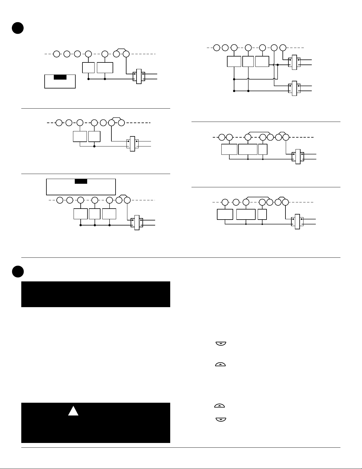
2. Connect wires beneath terminal screws on base using appropriate wiring schematic (see figs. 2 through 7).
3. Place base over hole in wall and mark mounting hole locations
on wall using base as a template.
4. Move base out of the way. Drill mounting holes.
5. Fasten base loosely to wall, as shown in fig. 1, using two
mounting screws. Adjust until level, and then tighten screws.
(Leveling is for appearance only and will not affect thermostat
operation.) If you are using existing mounting holes, or if holes
drilled are too large and do not allow you to tighten base
snugly, use plastic screw anchors to secure subbase.
6. Push excess wire into wall and plug hole with a fire-resistant
material (such as fiberglass insulation) to prevent drafts from
affecting thermostat operation.
Battery Location
This thermostat requires 2 “AAA” alkaline batteries to operate.
If “LO BATTERY” is displayed, the batteries are low and should
be replaced with fresh “AAA” Energizer® alkaline batteries. To
replace the batteries, install the batteries along the top of the base
(see fig. 1). The batteries must be installed with the positive(+)
ends to the right.
www.white-rodgers.com
Page 3
MOUNTING AND WIRING
4
CONTINUED FROM SECOND PAGE
Y
Y
Cooling
System
NOTE
Y
Cooling
System
G W
Fan
Relay
G W
Fan
Relay
G W
Fan
Relay
OB
NOTE
For 2-wire Heat only,
attach to RH and W
Figure 2. Typical wiring diagram for
heat only, 3-wire, single transformer systems
Figure 3. Typical wiring diagram for
cool only, 3-wire, single transformer systems
RED jumper wire (provided with thermostat) must be
connected between thermostat RH and RC terminals
for proper thermostat operation with this system.
OB
Figure 4. Typical wiring diagram for
heat/cool, 4-wire, single transformer systems
Heating
System
Heating
System
RCOB
JUMPER
RC
JUMPER
WIRE
24 VAC
WIRE
RH
24 VAC
TRANSFORMER
THERMOSTAT
RH
SYSTEM
TRANSFORMER
JUMPER
WIRE
RH
RC
24 VAC
TRANSFORMER
THERMOSTAT
SYSTEM
Hot
120 VAC
Neutral
Hot
120 VAC
Neutral
THERMOSTAT
SYSTEM
Hot
120 VAC
Neutral
OB
Y
Cooling
System
G W
Fan
Relay
Heating
System
THERMOSTAT
RH
RC
SYSTEM
24 VAC
HEATING
TRANSFORMER
24 VAC
COOLING TRANSFORMER
Hot
120 VAC
Neutral
Hot
120 VAC
Neutral
Figure 5. Typical wiring diagram for
heat/cool, 5-wire, two-transformer systems
G W
Fan
JUMPER
WIRE
RCOB
24 VAC
THERMOSTAT
RH
SYSTEM
TRANSFORMER
Hot
120 VAC
Neutral
JUMPER
WIRE
Y
Reversing
Compressor
Valve*
Contactor
* Reversing valve is energized when the
system switch is in the COOL position
Relay
Figure 6. Typical wiring diagram for heat pump
with reversing valve energized in COOL
G W
Fan
JUMPER
WIRE
RCOB
24 VAC
THERMOSTAT
RH
SYSTEM
TRANSFORMER
Hot
120 VAC
Neutral
JUMPER
WIRE
Y
Reversing
* Reversing valve is energized when the
system switch is in the HEAT position
Valve*
Compressor
Contactor
Relay
Figure 7. Typical wiring diagram for heat pump
with reversing valve energized in HEAT
CHECK THERMOST A T OPERA TION
5
NOTE
To prevent static discharge problems, touch side of thermostat to release static build-up before touching any keys.
If at any time during testing your system does not operate
properly, contact a qualified serviceperson.
Fan Operation
If your system does not have a G terminal connection, skip to
Heating System.
1. Turn on power to the system.
2. Move FAN switch to ON position. The blower should begin to
operate.
3. Move FAN switch to AUTO position. The blower should stop
immediately.
Cooling System
CAUTION
!
To prevent compressor and/or property damage, if the
outdoor temperature is below 50°F, DO NOT operate the
cooling system.
This thermostat has a time delay between cooling cycles to allow
the head pressure in the compressor to stabilize. If the temperature is adjusted to call for cool within 5 minutes of the last cycle the
snowflake icon will blink indicating the thermostat is locked out.
After 3 to 5 minutes, the compressor will start and the snowflake
icon will stop flashing. This helps prevent the compressor from
cycling too quickly and is normal operation for the thermostat.
1. Move SYSTEM switch to COOL position.
2. Press
to adjust thermostat setting below room temperature. The blower should come on immediately on high speed,
followed by cold air circulation
3. Press to adjust temperature setting above room temperature. The cooling system should stop operating.
Heating System
1. Move SYSTEM switch to HEAT position. If the heating system
has a standing pilot, be sure to light it.
2. Press to adjust thermostat setting above room temperature. The heating system should begin to operate.
3. Press to adjust temperature setting below room temperature. The heating system should stop operating.
www.white-rodgers.com
Page 4
CHECK THERMOST A T OPERA TION
5
CONTINUED FROM THIRD PAGE
Before you begin using your thermostat, you should be familiar
with its features and with the display and the location and
operation of the thermostat buttons. Your thermostat consists of
two parts: the thermostat cover and the base. To remove the
cover, gently pull it straight out from the base. To replace the
cover, line up the cover with the base and press gently until the
cover snaps onto the base.
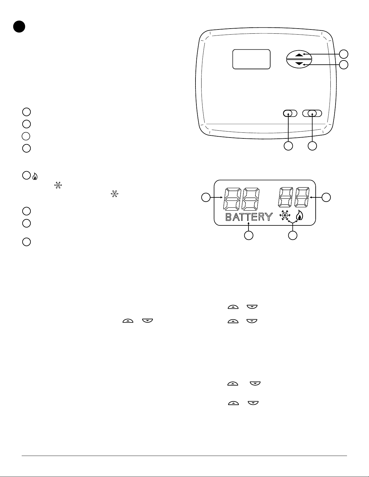
The Thermostat Buttons and Switches
1
(Up arrow) Raises temperature setting.
(Down arrow) Lowers temperature setting.
2
3
FAN switch (ON, AUTO).
SYSTEM switch (COOL, OFF, HEAT).
4
The Display
5
is displayed when the SYSTEM switch is in the HEAT
position. is displayed (non-flashing) when the SYSTEM
switch is in the COOL position. is displayed (flashing)
when the compressor is in lockout mode.
6
Displays current temperature.
WHITE-RODGERS
FAN SYS TE M
3
1
2
OFFON AUTO COOL HEAT
4
86
7
“LO BATTERY” is displayed when the 2 “AAA” batteries are
low and should be replaced. Nothing else will be displayed.
Displays currently set temperature (this is blank when
8
SYSTEM switch is in the OFF position).
Operating Features
Now that you are familiar with the thermostat buttons and display,
read the following information to learn about the many features of
the thermostat.
• SIMULTANEOUS HEATING/COOLING SETPOINT STORAGE — You can enter both your heating and cooling setpoints
at the same time. There is no need to re-enter the thermostat
at the beginning of each season.
• TEMPERATURE SETTING — Press or until the
display shows the temperature you want. The thermostat will
keep the room temperature at the selected temperature.
•
°F/°C CONVERTIBILITY — The factory default setting is
Fahrenheit. Clipping W904 jumper on the circuit board (see
fig. 1) will alter this feature to Celsius temperature setting.
• LOW BATTERY INDICATOR — If the 2 “AAA” alkaline
batteries are low and should be replaced, the display will be
blank except for “LO BATTERY”. When the batteries are low,
pressing any button will cause the display to operate for ten
seconds. After ten seconds, the display will be blank except for
“LO BATTERY”. After “LO BATTERY” has been displayed for
4 weeks, the thermostat will raise the temperature 10° above
your setpoint in COOL mode and drop the temperature 10°
below your setpoint in HEAT mode. You cannot program with
low batteries, but you can override setpoint temperature.
57
Figure 8. Thermostat display, buttons, and switches
• TEMPERATURE DISPLAY ADJUSTMENT — Your new
thermostat has been accurately set in our factory. However,
if you wish, you may adjust your new thermostat temperature
display to match your old thermostat. This can be accomplished (within a ±3° range) as follows:
1. Press
the SYSTEM switch in OFF position.
2. Press or to adjust the displayed temperature to
your desired setting.
3. Move SYSTEM switch from OFF to exit the feature.
• DISPLAY BACKLIGHT — (Not available on earlier models.)
The display backlight improves display contrast in low lighting conditions. Selecting backlight ON will turn the light on for
a short period of time after any button is pressed. Selecting
backlight OFF (default) will keep the light off. Turn the display
backlight feature ON as follows:
1. Press and at the same time for two seconds with
the SYSTEM switch in HEAT position. The display will
alternately show “-L” AND “FF” (off).
2. Press or to change “FF” to “ON”.
3. Move SYSTEM switch to OFF to exit the feature.
or at the same time for two seconds with
www.white-rodgers.com
Page 5
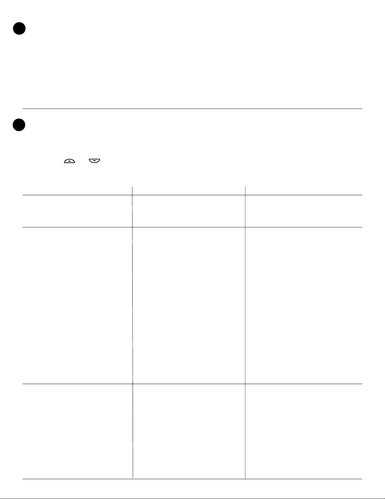
SPECIFICATIONS
6
ELECTRICAL DATA
Electrical Rating:
0 to 30 VAC 50/60 Hz. or D.C.
0.05 to 1.0 Amps (Load per terminal)
1.5 Amps Maximum Total Load (All terminals combined)
TROUBLESHOOTING
7
THERMAL DATA
Setpoint Temperature Range:
45°F to 90°F (7°C to 32°C)
Operating Ambient Temperature Range:
32°F to 105°F
Operating Humidity Range:
0 to 90% RH (non-condensing)
Shipping Temperature Range:
-40°F to 150°F
Reset Operation
If a voltage spike or static discharge blanks out the display or
causes erratic thermostat operation you can reset the thermostat by pressing and at the same time while moving
the SYSTEM switch from OFF to HEAT. This also resets the
factory defaults. If the thermostat has power, has been reset
and still does not function correctly contact your heating/cooling
service person or place of purchase.
Batteries
For optimum performance, we recommend replacing batteries
once a year with fresh “AAA” Energizer® alkaline batteries.
Symptom Possible Cause Corrective Action
No Heat/No Cool/No Fan 1. Blown fuse or tripped circuit breaker. Replace fuse or reset breaker.
(common problems) 2. Furnace power switch to OFF. Turn switch to ON.
3. Furnace blower compartment door or Replace door panel in proper position to engage
panel loose or not properly installed. safety interlock or door switch.
No Heat 1. Pilot light not lit. Re-light pilot.
2. SYSTEM Switch not set to HEAT. Set SYSTEM Switch to HEAT and raise setpoint
temperature above room temperature.
3. Loose connection to thermostat or system. Verify thermostat and system wires are securely
attached.
4. Furnace Lock-Out Condition. Heat may also Many furnaces have safety devices that shut
be intermittent. down when a lock-out condition occurs. If the
heat works intermittently contact the furnace
manufacturer or local service person for
assistance.
5. Heating system requires service or Diagnostic: Set SYSTEM Switch to HEAT and
thermostat requires replacement. raise the setpoint above room temperature. Within
a few seconds the thermostat should make a soft
click sound. This sound usually indicates the
thermostat is operating properly. If the thermostat
does not click, try the reset operation listed below .
If the thermostat does not click after being reset
contact your heating and cooling service person
or place of purchase for a replacement. If the
thermostat clicks, contact the furnace manufac
turer or a service person to verify the heating is
operating correctly.
No Cool 1. SYSTEM Switch not set to Cool. Set SYSTEM Switch to COOL and lower setpoint
temperature below room temperature.
2. Loose connection to thermostat or system. Verify thermostat and system wires are securely
attached.
3. Cooling system requires service or Same procedure as diagnostic for No Heat
thermostat requires replacement. condition except set the thermostat to COOL and
lower the setpoint below the room temperature.
There may be up to a five minute delay before the
thermostat clicks in Cooling.
www.white-rodgers.com
Page 6
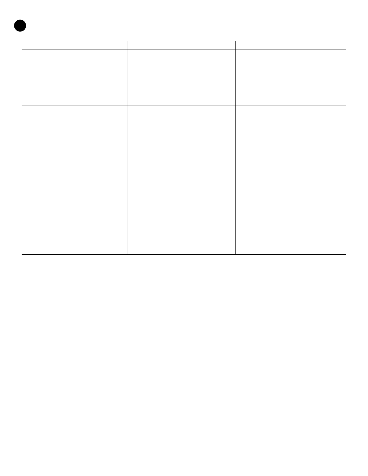
TROUBLESHOOTING
7
CONTINUED FROM FIFTH PAGE
Symptom Possible Cause Corrective Action
Heat, Cool or Fan Runs Constantly. 1. Possible short in wiring. Check each wire connection to verify they are not
2. Possible short in thermostat. shorted or touching together. No bare wire should
3. Possible short in heat/cool/fan system. stick out from under terminal screws. Try resetting
4. FAN Switch set to Fan ON. the thermostat as described above If the condition
persists the manufacturer of your system or
service person can instruct you on how to test the
Heat/Cool system for correct operation. If the
system operates correctly, replace the thermostat.
Furnace Cycles Too Fast or Too Slow 1. The location of the thermostat and/or the Digital thermostats normally provide precise
(narrow or wide temperature swing) size of the Heating System may be temperature control and may cycle faster than
influencing the cycle rate. some older mechanical models. A faster cycle
rate means the unit turns on and off more
frequently but runs for a shorter time so there is
no increase in energy use. If you would like to
increase the cycle time, clip Jumper W-905 as
mentioned in the instructions for Hydronic Heating
Systems. It is not possible to shorten the cycle
time. If an acceptable cycle rate is not achieved as
received or by clipping W-905 contact a local
service person for additional suggestions.
Cooling Cycles Too Fast or Too Slow 1. The location of the thermostat and the size The cycle rate for cooling is fixed and can not be
(narrow or wide temperature swing) of the Cooling System can influence the adjusted. Contact a local service person for
cycle rate. suggestions.
Thermostat Setting and Thermostat 1. Thermostat thermometer setting requires The thermometer can be adjusted +/- 3 degrees.
Thermometer Disagree adjustment. See Temperature Display Adjustment in the
Operation section.
Blank Display and/or Keypad 1. Voltage spike or static discharge. Replace batteries and check heat/cool system
Not Responding 2. Battery change required. for proper operation. If a voltage spike occurs use
the Reset Operation listed above.
www.white-rodgers.com
 Loading...