

Page 1
24A06G-1
DUAL LEVEL-TEMP
SILENT OPERATOR RELAY
(Normally Open Contacts)
INSTALLATION INSTRUCTIONS
Operator: Save these instructions for future use!
FAILURE TO READ AND FOLLOW ALL INSTRUCTIONS CAREFULLY BEFORE
INSTALLING OR OPERATING THIS CONTROL COULD CAUSE PERSONAL
INJURY AND/OR PROPERTY DAMAGE.
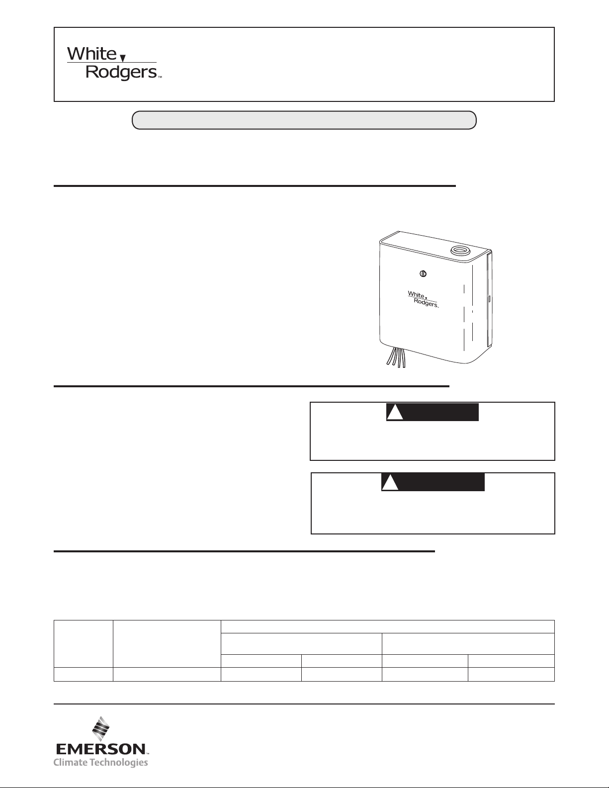
DESCRIPTION
This Dual Level-Temp Silent Operator Relay is designed for controlling two separate loads with a single low voltage thermostat.
It is especially suitable for use with electric heating equipment.
The Dual Level-Temp relay may be used to operate two separate
heating loads by means of a single low voltage thermostat. It
is equally well suited for use with a heating-cooling thermostat
to control heating and cooling loads alternately as in motels,
apartments, ofce buildings, etc.
This model Dual Level-Temp relay has a voltage input of 240
volts. Since this relay is equipped with a self-contained transformer, the supply voltage used must agree with the voltage
rating of the relay. This model has both an inductive and noninductive rating.
The Silent Operator relay has been carefully adjusted at the fac-
tory, and no attempt should be made to adjust them in the eld.
PRECAUTIONS
If in doubt about whether your wiring is millivolt, line, or low
voltage, have it inspected by a qualied heating and air conditioning contractor, electrician, or someone familiar with basic
electricity and wiring.
Do not exceed the specication ratings.
All wiring must conform to local and national electrical codes
and ordinances.
This control is a precision instrument, and should be handled
carefully. Rough handling or distorting components could cause
the control to malfunction.
To prevent electrical shock and/or equipment damage,
disconnect electric power to system at main fuse or
circuit breaker box until installation is complete.
Do not use on circuits exceeding specied voltage.
Higher voltage will damage control and could cause
shock or re hazard.
ELECTRICAL DATA
Switch Action: Two SPST switches, normally open
Thermal: Average time delay – 45 seconds
Ambient Temperature: -20° to 120°F (-24° to 49°C)
Mounting: 1/2" conduit hub or two key slot mounting holes
FOR SWITCH #1
TYPE
NUMBER
24A06G-1 240VAC, 60 Hz 25A, 6000W 12 FLA (72 LRA) 25A, 6000W 12 FLA (72 LRA)
*FLA - Full Load Amps.; LRA - Locked Rotor Amps.
INPUT
VOLTAGE /FREQUENCY
NON-INDUCTIVE INDUCTIVE* NON-INDUCTIVE INDUCTIVE*
(Red and Black Leads)
Thermostat Circuit Current:
Bimetal Heater #1 (Red & White Leads) – 0.21 Amps
Bimetal Heater #2 (Red & Black with White Stripe
Leads) – 0.21 Amps
ELECTRICAL RATING
CAUTION
!
WARNING
!
SPECIFICATIONS
(Red Striped and Black Striped Leads)
FOR SWITCH #2
www.white-rodgers.com
www.emersonclimate.com
PART NO. 37-4165D
Replaces 37-4165C
1236
Page 2
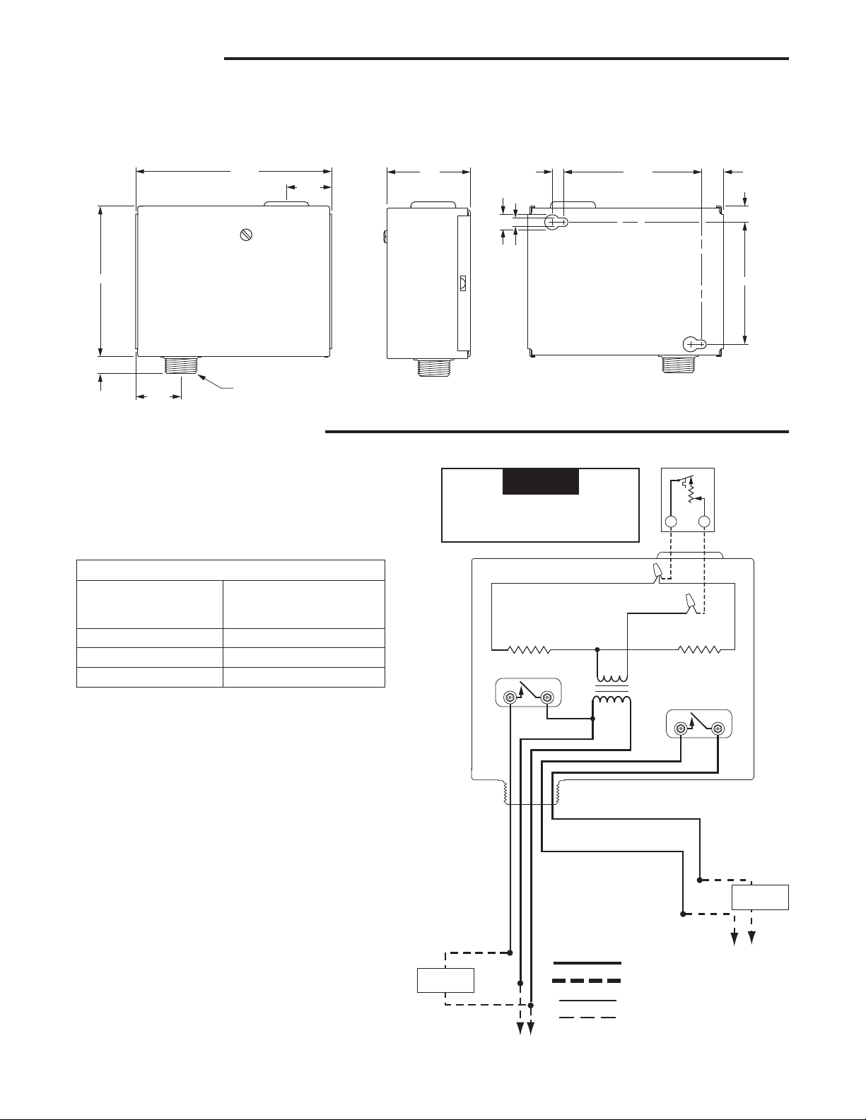
INSTALLATION
NOTE
The Dual-Level Temp relay may be mounted in any position
without affecting it's performance.
It can be connected using the 1/2" male conduit hub and can
be mounted to any standard junction box or wiring compartment.
4 15/16"
1 3/32"
3 25/32"
9/16"
1 3/32"
1/2" STD CONDUIT HUB
Fig. 1. Dimensions of Type 24A06 Dual Level Temp
WIRING AND OPERATION
All wiring should be done in accordance with local and national electrical codes and ordinances.
If a wiring diagram is supplied with the heating equipment, follow those instructions. If none is available, two diagrams are
presented which show different wiring methods for the Silent
Operator relay.
Connection Table
2-Wire Thermostat
(R & W)
Power Input: Black & Blue
Heat Load 1: Red & L2
Heat Load 2: Black w/Red stripe & L2
Black w/White stripe and
White to terminal W. Red to
terminal R.
It can also be mounted using the two holes in the back of
the case. Location of the mounting holes may be simplied by
holding the control against the mounting surface and marking
the proper position for drilling the holes.
2 1/8"
9/32"
3/8"
7/32"
Use thermostat with a .4A xed
heater, or set adjustable heater
in thermostat at .4A.
TYPE 24A06 DUAL LEVEL TEMP
BIMETAL
HEATER #1
SWITCH #1
3 15/32"
WHITE
RED
TRANSFORMER
W
BIMETAL
HEATER #2
SWITCH #2
2-WIRE
HEATING
THERMOSTAT
R
BLACK
W/WHITE
STRIPE
3 1/16"
9/16"
9/32"
OPERATION
As the thermostat closes its contacts, bimetal heaters #1 and
#2 are energized. Approximately 45 seconds later, the warping
action of these heaters closes line voltage switches #1 and #2
to energize heating loads #1 and #2.
When the thermostat opens its contacts, bimetal heaters #1
and #2 cool for approximately 45 seconds before line voltage
switches #1 and #2 open to de-energize the heating loads.
2
HEATING
LOAD #1
BLACK W/RED STRIPE
R
E
D
B
L
A
C
K
B
L
U
E
L1
LINE
RED W/BLACK STRIPE
L2
WIRING
Line Voltage
Line Voltage Field
Low Voltage
Low Voltage Field
HEATING
LOAD #2
L1 L2
LINE
Fig. 2. Using Two-wire Heating Thermostat to
Operate Two Separate Heating Loads
Page 3
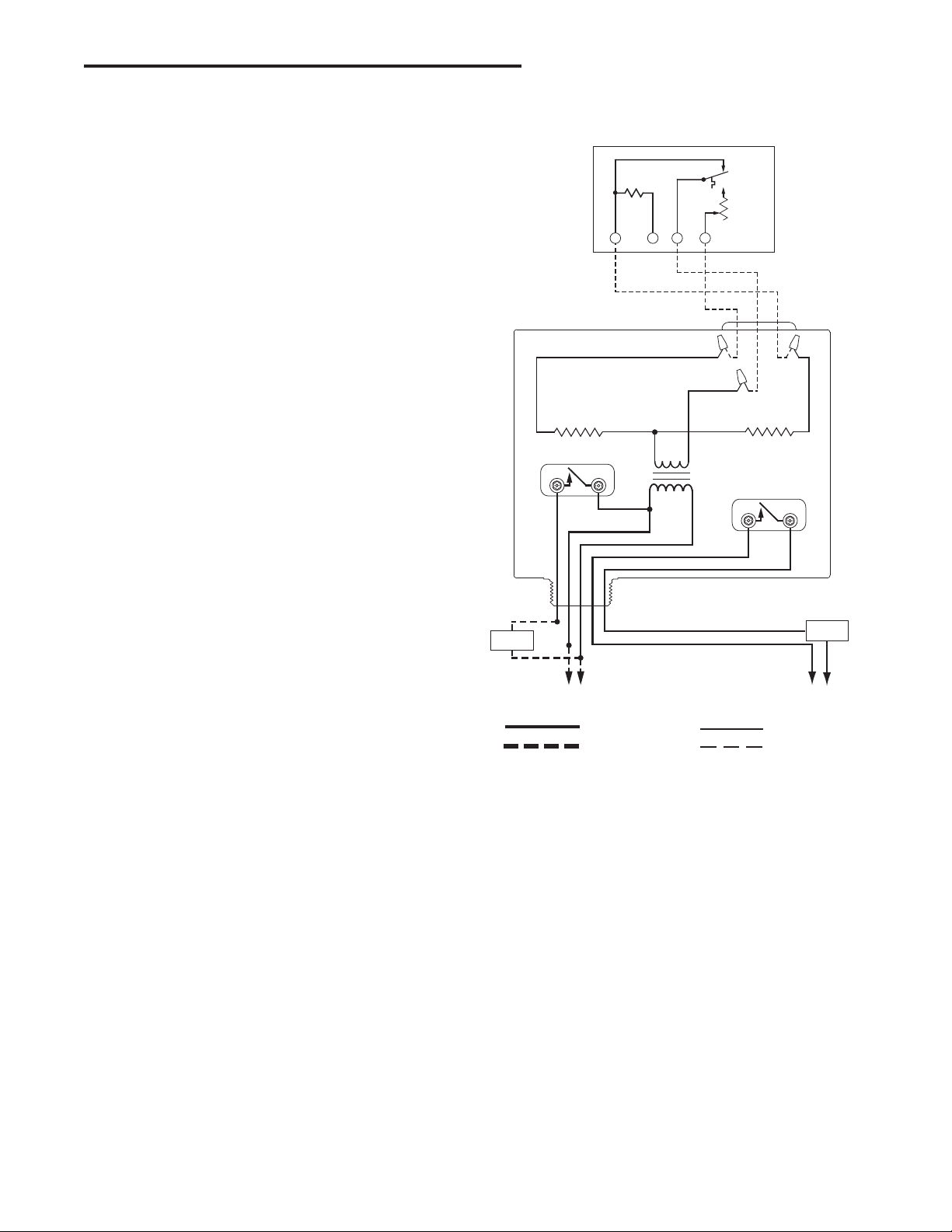
WIRING AND OPERATION (cont.)
All wiring should be done in accordance with local and national electrical codes and ordinances.
OPERATION
Heating
As the “Heat” contacts of the thermostat close, bimetal heater
#1 is energized. Approximately 45 seconds later, the warping
action of bimetal heater #1 closes line voltage switch #1 to energize the heating load. When the "Heat" contacts open, heater
#1 cools for approximately 45 seconds before switch #1 opens
to de-energize the heating load.
Cooling
As the "Cool" contacts of the thermostat close, bimetal heater
#2 is energized. Approximately 45 seconds later, the warping
action of bimetal heater #2 closes line voltage switch #2 to energize the cooling load. When the "Cool" contacts open, heater
#2 cools for approximately 45 seconds before switch #2 opens
to de-energize the cooling load.
TYPE 1F36 HEATING-COOLING THERMOSTAT
FIXED
COOLING
ANTICIPATOR
YORW
TYPE 24A06 DUAL LEVEL TEMP
BIMETAL
HEATER #1
SWITCH #1
THERMOSTAT
SWITCH
BIMETAL
WHITE
TRANSFORMER
RED
HEAT
ADJUSTABLE
HEATING
ANTICIPATOR
BIMETAL
HEATER #2
SWITCH #2
BLACK W/
WHITE STRIPE
HEATING
LOAD #1
RED
BLACK
BLUE
L1
L2
LINE
BLACK W/RED STRIPE
RED W/BLACK STRIPE
WIRING
Line Voltage Low Voltage
Line Voltage Field Low Voltage Field
Fig. 3. Using Heating-Cooling Thermostat to
Operate Heating and Cooling Loads
COOLING
L1
LINE
LOAD
L2
3
Page 4

White-Rodgers is a business
of Emerson Electric Co.
The Emerson logo is a
trademark and service mark
of Emerson Electric Co.
www.white-rodgers.com
www.emersonclimate.com
Page 5

www.emersonclimate.com
www.white-rodgers.com
de service d’Emerson Electric Co.
de commerce et une marque
Le logo d’Emerson est une marque
d’Emerson Electric Co.
White-Rodgers est une affaire
Page 6

3
THERMOSTAT DE CHAUFFAGE
de chauffage et une de climatisation
climatisation pour commander une charge
Fig. 3. Utilisation d’un thermostat de chauffage et
Champ à basse tension
Basse tension
Champ à la tension du réseau
Tension du réseau
CÂBLAGE
L2
RÉSEAU
L1
CLIMATISANTE 2
CHARGE
BLANC
RAYÉ
NOIR
CHAUFFANT 2
ÉLÉMENT
COMMUTATEUR 2
CHAUFFAGE
RÉGLABLE DE
ANTICIPATION
CHAUFAFGE
TRANSFORMATEUR
ROUGE
BLANC
BILAME
RÉSEAU
L2
L1
ROUGE RAYÉ NOIR
NOIR RAYÉ ROUGE
BLEU
NOIR
ROUGE
CHAUFFANTE 1
CHARGE
de climatisation.
COMMUTATEUR 1
CHAUFFANT 1
ÉLÉMENT
commutateur 2 est ouvert, ce qui met hors tension la charge
chauffant 2 refroidit pendant environ 45 secondes, puis le
Lorsque les contacts du thermostat sont ouverts, l’élément
du réseau, ce qui met sous tension la charge de climatisation.
ondes, l’élément chauffant ferme le commutateur 2 à la tension
l’élément chauffant 2 est mis sous tension. Après environ 45 secLorsque le contact de climatisation du thermostat est fermé,
Climatisation
COMMANDE « LEVEL TEMP » TYPE 24A06
de chauffage.
commutateur 1 est ouvert, ce qui met hors tension la charge
chauffant 1 refroidit pendant environ 45 secondes, puis le
Lorsque les contacts du thermostat sont ouverts, l’élément
YORW
du réseau, ce qui met sous tension la charge de chauffage.
ondes, l’élément chauffant ferme le commutateur 1 à la tension
l’élément chauffant 1 est mis sous tension. Après environ 45 sec-
CLIMATISATION
FIXE DE
THERMOSTAT
ANTICIPATION
COMMUATEUR DU
ET CLIMATISATION TYPE 1F36
Lorsque le contact de chauffage du thermostat est fermé,
Chauffage
FONCTIONNEMENT
Tout le câblage doit respecter les codes et règlements qui régissent les installations électriques.
CÂBLAGE ET FONCTIONNEMENT (suite)
Page 7

NOTE
RÉSEAU
L1 L2
CHAUFFANTE 1
CHARGE
BLANC
RAYÉ
NOIR
À 2 FILS
CHAUFFAGE
THERMOSTAT DE
2
pour commander deux charges de chauffage distinctes
Fig. 2. Utilisation d’un thermostat de chauffage à deux ls
RÉSEAU
L2
CÂBLAGE
U
E
L
B
ROUGE RAYÉ NOIR
NOIR RAYÉ ROUGE
COMMUTATEUR 2
TRANSFORMATEUR
CHAUFFANT 2
ÉLÉMENT
ROUGE
BLANC
W
R
Champ à basse tension
L1
Basse tension
Champ à la tension du réseau
Tension du réseau
R
I
E
O
G
N
U
O
R
CHAUFFANTE 1
CHARGE
ce qui met hors tension les charges de chauffage.
puis les commutateurs 1 et 2 à la tension du réseau sont ouverts,
chauffants 1 et 2 refroidissent pendant environ 45 secondes,
Lorsque les contacts du thermostat sont ouverts, les éléments
chauffage 1 et 2.
tension du réseau, ce qui met sous tension les charges de
ondes, ces éléments ferment les commutateurs 1 et 2 à la
chauffants 1 et 2 sont mis sous tension. Après environ 45 secLorsque les contacts du thermostat sont fermés, les éléments
FONCTIONNEMENT
COMMUTATEUR 1
CHAUFFANT 1
ÉLÉMENT
borne W. Rouge sur la borne R.
COMMANDE « LEVEL TEMP » TYPE 24A06
l’élément chauffant variable à 0,4 A.
Noir rayé blanc et blanc sur la
Tableau de raccordement
ment chauffant xe de 0,4 A ou régler
Utiliser un thermostat avec un élé-
Charge 2 de chauffage Noir rayé rouge & L2
Charge 1 de chauffage Rouge & L2
Alimentation Noir et bleu
(R & B)
Thermostat à 2 ls
qui gurent ici présentent deux façons de câbler le relais.
chauffage, alors s’y référer. Si aucun schéma n’est fourni, ceux
Si un schéma de câblage est fourni avec l’équipement de
9/16"
3 1/16"
9/32"
3 15/32"
9/32"
7/32"
3/8"
2 1/8"
la position des trous.
la commande contre la surface où on doit l’installer et reporter
du boîtier. Pour faciliter le perçage des trous de montage, placer
1 3/32"
Fig. 1. Dimensions de la commande « Level-Temp » jumelée de type 24A06
ORDINAIRE DE 1/2”
RACCORD DE CONDUIT
4 15/16"
Tout le câblage doit respecter les codes et règlements qui régissent les installations électriques.
CÂBLAGE ET FONCTIONNEMENT
1 3/32"
9/16"
3 25/32"
Il s’installe également à l’aide des deux trous situés à l’arrière
ou sur un panneau de câblage.
s’installe notamment dans une boîte de raccordement ordinaire
On le raccorde à l’aide du raccord de conduit mâle de 1/2”. Il
position, sans que cela n’en détériore le rendement.
Le relais « Level-Temp » jumelé s’installe dans n’importe quelle
INSTALLATION
Page 8

1236
Remplace 37-4165C
37-4165D
o
PIÈCE N
COMMUTATEUR 2
(Fil rouge et l noir à rayure blanche)
CHARGE ÉLECTRIQUE
www.emersonclimate.com
www.white-rodgers.com
NON-INDUCTIVE INDUCTIVE* NON-INDUCTIVE INDUCTIVE*
(Fil rouge et l noir)
COMMUTATEUR 1
* FLA : courant (A) à pleine charge. LRA : courant (A) avec rotor bloqué.
24A06G-1 240VAC, 60 Hz 25A, 6000W 12 FLA (72 LRA) 25A, 6000W 12 FLA (72 LRA)
FRÉQUENCE
TENSION ABSORBÉEE /
TYPE
No DE
blanche) : 0,21 A.
Élément chauffant 2 (l rouge et l noir à rayure
Élément chauffant 1 (l rouge et l blanc) : 0,21 A
Courant du circuit du thermostat :
Température ambiante : –24 à 49 °C (–20 à 120 °F).
ou deux trous de montage.
Installation : Raccord de conduit de 1/2”
Thermique : Délai moyen : 45 secondes.
nels (SPST) normalement ouverts.
Commutateur : Deux commutateurs unipolaires unidirection-
FICHE ÉLECTRIQUE
SPÉCIFICATIONS
d’électro cution et d’incendie.
peut endomma ger la commande et poser des risques
passent la tension nominale. Une tension trop élevée
Ne pas installer cet appareil sur des circuits qui dé-
!
AVERTISSEMENT
toute la durée de l’installation.
panneau de distribution électrique principal pendant
mages matériels, couper l’alimentation du système au
Pour prévenir les risques d’électrocution et de dom-
!
ATTENTION
PRÉCAUTIONS
de façon négligente ou si des composants sont déformés.
manipulé avec soin. Elle peut se détraquer si elle est manipulée
Cette commande est un instrument de précision qui doit être
sent les installations électriques.
Tout le câblage doit respecter les codes et règlements qui régis-
Ne pas dépasser les charges nominales.
entre preneur en chauffage agréé.
réseau), faire inspecter celui-ci par un maître-électricien ou un
système (soit en millivolts, à basse tension ou à la tension du
En cas d’incertitude concernant la tension d’alimentation du
tive ne devrait être faite pour l’ajuster par après.
Le relais silencieux est réglé avec soin à l’usine. Aucune tenta-
et non inductives.
relais. Il est également homologués pour des charges inductives
sion d’alimentation doit correspondre à la tension nominale du
à l’entrée. Puisqu’il est doté d’un transformateur intégré, la tenCe relais « Level-Temp » jumelé accepte une tension de 240 volts
appartements, immeubles de bureaux, etc.
et climatisation; cette application est idéale pour les motels,
et une de climatisation à l’aide d’un thermostat de chauffage
aussi pour commander en alternance une charge de chauffage
tinctes à l’aide d’un seul thermostat à basse tension. Il convient
Il peut servir pour commander deux charges de chauffage dis-
de chauffage électrique.
à basse tension. Il convient particulièrement aux équipements
mander deux charges distinctes à l’aide d’un seul thermostat
Le relais silencieux « Level-Temp » jumelé est conçu pour com-
DESCRIPTION
SURES ET DE DOMMAGES MATÉRIELS.
ET D’UTILISER LA COMMANDE AFIN DE PRÉVENIR LES RISQUES DE BLESPRIÈRE DE LIRE ATTENTIVEMENT CES INSTRUCTIONS AVANT D’INSTALLER
INSTRUCTIONS D’INSTALLATION
TYPE 24A06G-1
(À contacts normalement ouverts)
« LEVEL-TEMP » JUMELÉ
RELAIS SILENCIEUX
Utilisateur : Conserver ces instructions à titre de référence!
 Loading...