

White Rodgers 241-2 User Manual [en, es, fr]
241-2, 1605-64 & 1609 Series
WARNING
!
CAUTION
Refrigeration Temperature Controls
INSTALLATION INSTRUCTIONS
Operator: Save these instructions for future use!
FAILURE TO READ AND FOLLOW ALL INSTRUCTIONS CAREFULLY BEFORE
INSTALLING OR OPERATING THIS CONTROL COULD CAUSE PERSONAL
INJURY AND/OR PROPERTY DAMAGE.
DESCRIPTION
This hydraulic action temperature control is applicable for all
types of commercial or industrial refrigeration applications. This
control will close contacts on rise in temperature and open them
on a fall in temperature.
This control has a two-circuit contact structure which will simultaneously close two circuits on a rise of temperature and open
them on a fall of temperature.
PRECAUTIONS
FIRE/SHOCK HAZARD
Disconnect power to system at main fuse
or circuit breaker box before installation.
Do not use on circuits exceeding
specified voltages.
FREEZE HAZARD
Install low temperature limit device.
System malfunction may cause freeze
damage.
This two-circuit control is intended for use on zoning systems
where all controls operate a common compressor but operate
a separate solenoid refrigerant valve in each zone.
THIS CONTROL MUST BE INSTALLED BY A QUALIFIED
INSTALLER.
All wiring must conform to local and national electrical codes
and ordinances.
This control is a precision instrument, and should be handled
carefully. Rough handling or distorting components could cause
the control to malfunction.
This control has been accurately calibrated at the factory. Any
attempt to re-calibrate this control will void the White-Rodgers
warranty.
If in doubt about whether your wiring is millivolt, low or line voltage, have it inspected by a qualified heating and air conditioning
contractor or a licensed electrician.
Label all wires prior to disconnection when servicing controls.
Wiring errors can cause improper and dangerous operation.
Following installation or replacement, follow appliance manufacturers’ recommended installation/service instructions to insure
proper operation.
INSTALLATION
The switch mechanism of this control may be mounted in any
location, provided that the temperature and humidity of the
air in which it is located do not cause a condensation on the
switch parts.
The sensitive element, or “bulb”, should be located in the aver-
age temperature of the controlled area.
Capillary tubing should be led over a path that protects it from
damage from blows, cuts, etc., and should be installed without
kinking or twisting. The tubing should be attached to some surface
at frequent intervals along its length, and should not hang loosely.
Excess tubing should be coiled and secured at a convenient
protected location close to the switch mechanism.
The bulb should be handled with reasonable care, as a dent or
sharp bend may change the calibration and cause the control
to cycle at a temperature different from the dial setting.
Refrigeration and temperature controls are calibrated and
tested under controlled manufacturing conditions. Published
specifications do not include normal manufacturing specifications. Minor differences in performance could be expected as
conditions change.
www.white-rodgers.com
www.emersonclimate.com
PART NO. 37-1104H
Replaces 37-1104G
1018
WIRING
Temperature
control
Low
temperature
limit
High side
pressure control
(if used)
To
Compressor
Motor
Line
L1
L2
Note: Make L1 “HOT” on
120V installation
Temperature
control
Low temperature
limit
Suction
pressure
control
High side
pressure
control
Motor
starter
Solenoid
refrigerant
valve
To
Compressor
Motor
Line
L1
L2
Note: Make L1 “HOT” on 120V installation
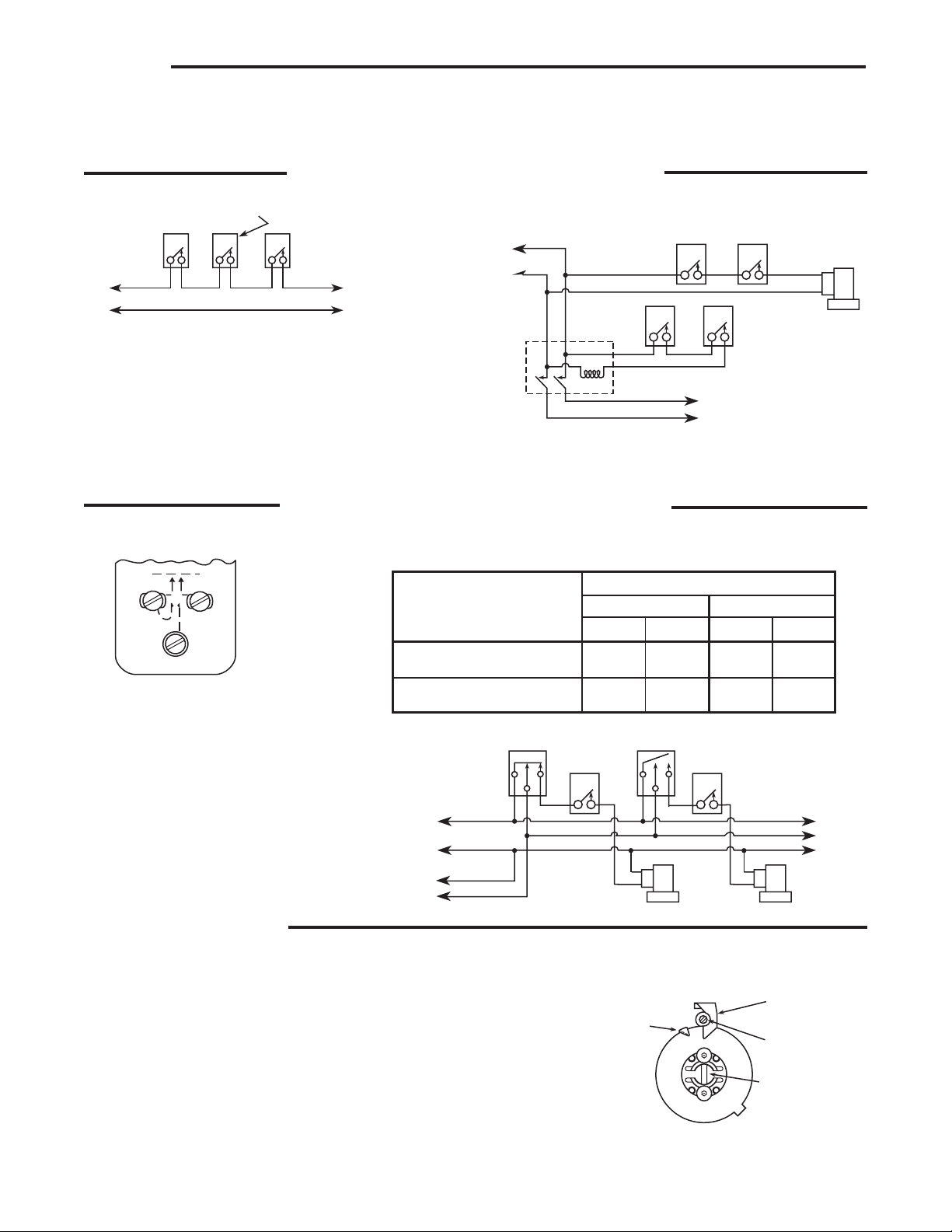
"B" Fixed indicator
(cut-out point)
"C" Differential
adjusting screw
"D" Movable indicator
(cut-in point)
"A" Adjusting
slot
BLUE
RED
WHITE
240V
22.2A
22.2A
LOAD CONDITIONS
MAXIMUM ALLOWABLE RATING
Full Load Locked Rotor
120V
7.4A
7.4A
120V
44.5A
44.5A
240V
3.7A
3.7A
Load between Blue and Red
terminals must not exceed:
Load between Blue and White
terminals must not exceed:
To
Additional
Units
B
R
W
B
R
W
Valve
No. 2
Valve
No. 1
Blue
White
Red
To
Compressor
Motor
Line
L1
L2
Note: Make L1 “HOT” on
120V installation
Temperature
control
Temperature
control
Low
temperature
limit
Low
temperature
limit
All wiring must conform to local and national electrical codes and ordinances.
Connect in accordance with wiring diagrams provided by the equipment manufacturer. If none are provided, the following repre-
sents a typical installation.
Controls with one circuit (two terminals)
Typical Refrigeration Pump Down Circuit
Circuit showing temperature control controlling compressor directly.
Circuit showing temperature control to open and close refrigerant valve. Suction
pressure control starts and stops compressor through motor starter.
Controls with two circuits (three terminals)
This diagram shows a typical two-circuit
application. Several zones receive refrigeration from the same compressor,
but each zone requires its own solenoid
refrigerant valve, temperature control and
limit control.
SETTING THE DIAL
The movable indicator (D) points to the temperature at which
the compressor starts. The fixed indicator (B) points to the
temperature at which the compressor will stop. The difference
between these two indicators is the differential. Follow these
instructions to set the dial:
1. Insert a screwdriver in the adjusting slot (A) and turn the
dial until the fixed indicator (B) points to the temperature at
which the compressor is to stop.
2. Turn the differential adjusting screw (C) until the movable
indicator (D) points to the temperature at which the compressor is to start.
The blue terminal is common. The table below shows the maximum load allowed between terminals.
Séries 241-2, 1605-64 et 1609
AVERTISSEMENT
!
ATTENTION
Commandes de température de réfrigération
INSTRUCTIONS D’INSTALLATION
Opérateur : Il faut conserver ces instructions pour utilisation ultérieure !
IL FAUT LIRE ET SUIVRE SOIGNEUSEMENT TOUTES CES INSTRUCTIONS
AVANT D’INSTALLER OU D’UTILISER CETTE COMMANDE POUR ÉVITER DES
BLESSURES ET/OU D’ENDOMMAGER L’ÉQUIPEMENT.
DESCRIPTION
Cette commande hydraulique de température est applicable à
tous les types d’applications de réfrigération commerciale ou industrielle. Cette commande ferme les contacts quand en montée
de température et les ouvre en descente de température.
Cette commande a une structure de contacts pour deux circuits
qui ferme simultanément deux circuits quand la température
monte et les ouvre quand elle descend.
PRÉCAUTIONS
DANGER D’INCENDIE / RISQUE
DE CHOC ÉLECTRIQUE
Avant l’installation, couper le courant
vers le système à partir dela boîte
principale de fusible ou de
disjoncteurs.
Ne pas utiliser sur des circuits avec une
tension supérieure à celle spécifiée.
DANGER DE GEL
Installer le limiteur de basse
température.
Un mauvais fonctionnement du
système peut provoquer des
dommages dus au gel.
Cette commande pour deux circuits est prévue pour utilisation dans les systèmes à plusieurs zones où toutes les commandes font fonctionner un seul compresseur commun, mais
font fonctionner une vanne solénoïde de réfrigération séparée
pour chaque zone.
CETTE COMMANDE DOIT ÊTRE INSTALLÉE PAR UN TECHNICIEN QUALIFIÉ.
Tous les branchements doivent être conformes aux codes
électriques et aux règlements locaux et nationaux.
Cette commande est un instrument de précision qui doit être
manipulée avec précaution. Une manutention mala droite ou la
déformation des composants peut causer un mauvais fonctionnement de la commande.
Cette commande a été étalonnée avec précision à l’usine. Toute
tentative d’étalonnage de cette commande annule la garantie
de White-Rodgers.
En cas de doute en ce qui concerne la tension de la ligne, la
faire vérifier par un technicien de chauffage et de climatisation
ou un électricien qualifié.
Lors d’une intervention, il faut identifier tous les fils avant de les
débrancher. Un mauvais bran chement peut causer un mauvais
fonctionnement qui peut être dangereux.
Après l’installation ou le remplacement, suivre les instructions
d’installation recommandées par le fabricant de l’appareil pour
assurer le bon fonctionnement.
INSTALLATION
Le mécanisme de commutation de cette commande peut être
monté dans n’importe quel endroit dont l’humidité et la température ambiante ne causent pas de condensation sur les pièces
des commutateurs.
L’élément sensitif ou l’“ampoule” doit se trouver à une tempéra-
ture moyenne de la zone de contrôle.
Le tube capillaire doit être installé de façon à être protégé
contre les chocs, les coupures, etc. et installé sans le pin cer ni le tordre. Le tube doit être attaché sur une surfa ce rigide, à intervalles fréquents, sur toute sa longueur et
ne doit pas pendre. Il faut enrouler l’excès de tube et le maintenir
à un endroit pratique près du mécanisme de commutation.
Il faut manipuler l’ampoule avec des soins raisonnables, car une
déformation ou un pli abrupt change l’étalonnage et provoque
un contrôle de cycle à une température différente que celle
sélectionnée.
Les commandes de réfrigération et de température sont calibrées et testées dans des conditions de fabrication contrôlées.
Les spécifications publiées n’incluent pas les spécifications de
fabrication standard. De légers écarts de performance peuvent
survenir selon les changements de conditions.
www.white-rodgers.com
www.emersonclimate.com
No. DE PIÈCE 37-1104H
Remplace 37-1104G
1018
 Loading...