

Page 1
Operator: Save these instructions for future use!
FAILURE TO READ AND FOLLOW ALL INSTRUCTIONS CAREFULLY
BEFORE INSTALLING OR OPERATING THIS CONTROL COULD CAUSE
PERSONAL INJURY AND/OR PROPERTY DAMAGE.
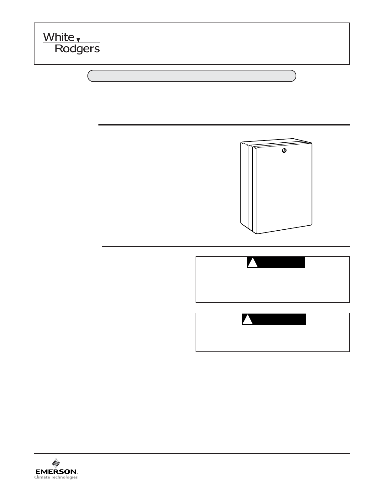
DESCRIPTION
This Evaporative Cooler Control has a rain-proof enclosure and can be used with either 120 VAC or 240 VAC
systems. It was designed for use with White-Rodgers
1F51-619, 1F51W-619, or 1D51W-632 Thermostats to
provide automatic temperature and ventilation control
and remote fan speed selection of an evaporative cooler
with 2-speed fan. The pump relay is automatically operated to allow wetting of cooler pads before starting fan.
8A18Z-2
Evaporative Cooler Control
INSTALLATION INSTRUCTIONS
PRECAUTIONS
If in doubt about whether your wiring is millivolt, line, or low
voltage, have it inspected by a qualified heating and air
conditioning contractor, electrician, or someone familiar
with basic electricity and wiring.
Do not exceed the specification ratings.
All wiring must conform to local and national electrical
codes and ordinances.
This control is a precision instrument, and should be
handled carefully. Rough handling or distorting components could cause the control to malfunction.
CAUTION
!
To prevent electrical shock and/or equipment
damage, disconnect electric power to system, at
main fuse or circuit breaker box, until installation
is complete.
WARNING
!
Do not use on circuits exceeding specified voltage. Higher voltage will damage control and could
cause shock or fire hazard.
www.white-rodgers.com
PART NO. 37-5918C
Replaces 37-5918B
0720
Page 2
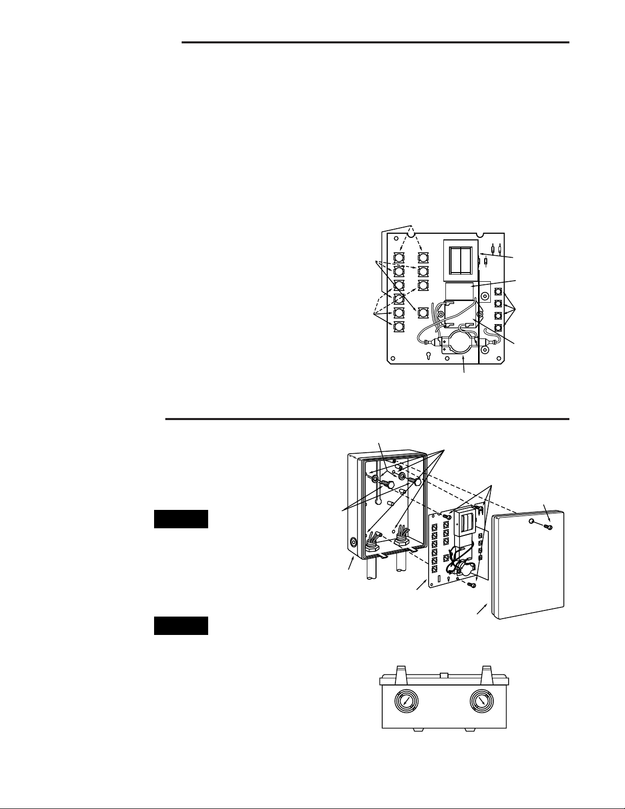
SPECIFICATIONS
Case
Panel
Cover
Flat washers
Bolts
Mounting holes
for four bolts
and washers
Panel mounting
screws
Cover
screw
Figure 2. Installing control
Electrical Ratings:
Input Voltage: 120 or 240 VAC, 60 Hz.
Operating Ambient Temperature Range:
40 to 150°F (5 to 65°C)
Power Consumption:
6 Watts nominal with all three relays energized
Fan Rating:
12 FLA., 72 LRA; 120 VAC
6 FLA., 36 LRA; 240 VAC
Pump Rating:
10 FLA., 60 LRA: 120 VAC
5 FLA., 30 LRA; 240 VAC
The 8A18Z-2 Evaporative Cooler Control consists of
three relays and a low voltage transformer with dual
voltage primary. The pump relay is automatically operated, which allows the cooler pads to become wet before
the fan starts. This will eliminate the fan from blowing dust,
warm air, and odor on initial start-up. The fan relay
controls operation of the fan without the pump when the
thermostat subbase is in the vent position, and controls
operation of both fan and pump when the thermostat
subbase is in the cool position.
Combined Total Connected Load:
16 FLA., 120 VAC
8 FLA., 240 VAC
Mounting:
Four 9¦32” Dia. holes
(2 1¦2” x 5” center line to center line)
Dimensions:
6” wide x 8” high x 3” deep
Line
connections
120V
120V
120V
240V
L2
240V
P2
240V
F2
P1
Fan timer
relay
Pump
connections
Fan
connections
N
P2
F2
L1
LO
HI
Figure 1. Panel assembly
8A18Z-2
R
W
Y
G
Low voltage
transformer
Pump relay
Low voltage
thermostat
connections
Fan
speed
relay
INSTALLATION
1. Remove cover screw. To remove cover, pull cover
outward at the top, then lift cover off the locating tabs
at the bottom of the case.
2. Remove panel assembly from case and discard packing material.
NOTE
Place panel assembly in a safe location to prevent damage to the panel while installing the case.
3. Determine which knockouts will be used for electrical
conduits, then remove electrical knockouts from case
before mounting.
If the larger knockout is to be removed, remove the
smaller knockout before removing the larger one.
4. To remove the knockouts, place a screwdriver on
the knockout at the location indicated by the arrow
(see fig. 3). Tap the screwdriver to pop the knockout
out of the case. If the knockout is not completely
removed, carefully use pliers to twist the knockout
until it comes out.
NOTE
Figure 3. Electrical knockouts
2
Page 3

INSTALLATION (cont’d)
5. Select an appropriate location for mounting the control. Position the case on a smooth flat surface in a
vertical position only (with electrical knockouts down).
Mount the case using flat washers and screws (not
provided) through the four mounting holes in the back
of the case.
NOTE
Install conduit, then run wiring and install the thermostat
according to thermostat installation instructions (included
with thermostat) before installing panel assembly in
case.
CAUTION
!
Non-metallic enclosure does not provide grounding between conduit connections. Use grounding
bushings and jumper wires to ensure proper
grounding of control.
6. After wiring is run into case, bend the wires out slightly
so that the wires will be in front of the panel assembly
when it is installed.
7. Loosen the three panel mounting screws in the case
approximately one turn. Slide the two slots located at
the top of the panel assembly under the two mounting
screws at the top of the case. Lower the panel assembly into the case until the bottom mounting screw
protrudes through the keyhole slot on the panel. Slide
the panel assembly up toward the top of the case, then
hold the panel assembly in place while tightening all
three mounting screws.
All wiring should be done in accordance with local and
national electrical codes and ordinances.
N
120V
HOT
GND
PUMP MOTOR
(120 V)
COM
2-SPEED FAN
L2
HOT
240V
L1
HOT
GND
PUMP MOTOR
(240 V)
COM
2-SPEED FAN
L0
HI
(120 V)
L0
HI
(240 V)
Figure 4. Typical wiring diagrams
120 VAC DIAGRAM
N
L2
120V
240V
P2
P2
120V 240V
F2
F2
120V 240V
P1
L1
PUMP
RELAY
L0
LO SPEED
FAN
HI SPEED
FAN
FAN
TIMER
RELAY
HI
240 VAC DIAGRAM
N
L2
120V
240V
P2
P2
120V 240V
F2
F2
120V 240V
P1
L1
PUMP
RELAY
L0
LO SPEED
FAN
HI SPEED
FAN
FAN
TIMER
RELAY
HI
1F51-619 or 1F51W-619 THERMOSTAT
8A18Z-2
PUMP
RELAY
FAN SPEED
RELAY
FAN TIMER
RELAY
INTERNAL WIRING
FIELD INSTALLED WIRING
ELECTRICAL CONNECTION
1F51-619 or 1F51W-619 THERMOSTAT
8A18Z-2
PUMP
RELAY
FAN SPEED
RELAY
FAN TIMER
RELAY
INTERNAL WIRING
FIELD INSTALLED WIRING
ELECTRICAL CONNECTION
W Y G
R
R
W
Y
G
W Y G
R
R
W
Y
G
CAUTION
!
Do not over tighten panel mounting screws to
avoid damage to the panel assembly.
8. Connect wires to proper terminals (see fig. 4 for typical
wiring connections).
CAUTION
!
Do not press against panel assembly while tightening terminal screws to avoid damage to the
panel assembly.
9. Replace cover and test operation per the checkout
section.
WIRING
CAUTION
!
To prevent electrical shock and/or equipment
damage, disconnect electric power to system at
main fuse or circuit breaker box until installation
is complete.
CHECKOUT
1. After mounting and wiring has been completed, set
thermostat switch to “OFF” position and fan switch to
“LO” position. Turn thermostat lever to “5” and thermostat switch to “COOL”. Nothing should happen provided the room temperature is below 95°F.
2. Turn thermostat lever to “1”. The pump should start
immediately, provided the room temperature is above
55°F.
3. After a time delay of 30 to 120 seconds to allow the
cooling pads to become soaked, the fan should start
running at low speed.
4. Turn fan switch to “HI” position. The fan should now be
operating on high speed.
5. Turn thermostat switch to “VENT” position. The pump
should stop immediately.
6. Turn the thermostat switch to “OFF” position. After a
delay of 3 to 30 seconds, the fan should stop running.
3
Page 4

White-Rodgers is a division
of Emerson Electric Co.
The Emerson logo is a
trademark and a service mark
of Emerson Electric Co.
TECH SUPPORT HELP LINE: 1-800-284-2925
St. Louis, Missouri
www.white-rodgers.com
 Loading...