

Page 1
OPERATOR’S MANUAL
Model Series
950-959
960-969
E960-E969
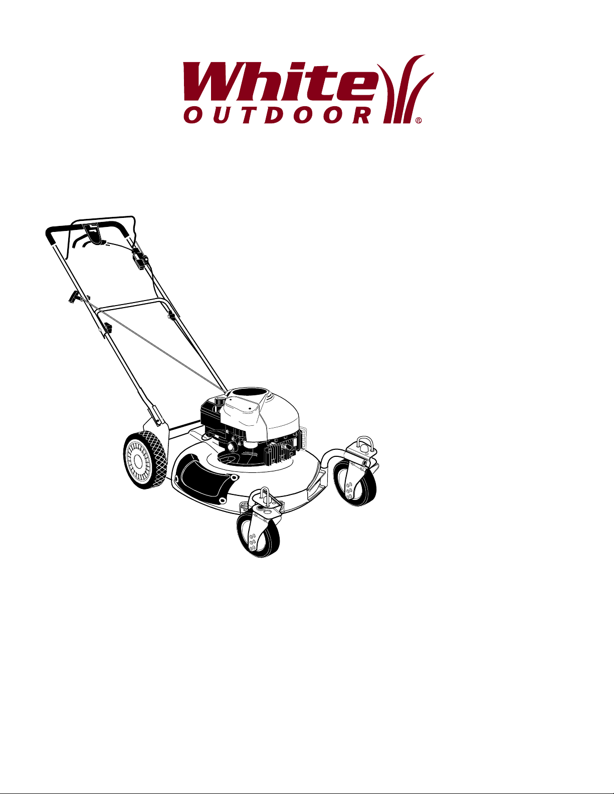
Model 969D Shown
IMPORTANT: READ SAFETY RULES AND INSTRUCTIONS CAREFULLY
Warning: This unit is equipped with an internal combustion engine and should not be used on or near any unimproved forest-
covered, brush-covered or grass-covered land unless the engine’s exhaust system is equipped with a spark arrester meeting
applicable local or state laws (if any). If a spark arrester is used, it should be maintained in effective working order by the operator.
In the State of California the above is required by law (Section 4442 of the California Public Resources Code). Other states may have
similar laws. Federal laws apply on federal lands. A spark arrester for the muffler is available through your nearest engine authorized
service dealer or contact the service department, P.O. Box 361131 Cleveland, Ohio 44136-9722.
WHITE OUTDOOR PRODUCTS COMPANY P.O. BOX 361131 CLEVELAND, OHIO 44136-9722
PRINTED IN U.S.A.
FORM NO.
770-10061A.fm
(12/99)
Page 2
TABLE OF CONTENTS
Content Page
Important Safe Operation Practices .................................................................. 3
Slope Gauge..................................................................................................... 6
Unpacking Instructions...................................................................................... 7
Assembling Your Lawn Mower.......................................................................... 8
Know Your Lawn Mower.................................................................................... 9
Operating Your Lawn Mower............................................................................. 11
Making Adjustments.......................................................................................... 14
Maintaining Your Lawn Mower .......................................................................... 15
Service.............................................................................................................. 21
Off-Season Storage .......................................................................................... 21
Troubleshooting ................................................................................................ 22
Parts List ........................................................................................................... 23
FINDING MODEL NUMBER
This Operator’s Manual is an important part of your new Lawn Mower. It will help you assemble, prepare and
maintain the unit for best performance. Please read and understand what it says.
Before you start assembling your new equipment, please locate the model plate on the
equipment and copy the information from it in the space provided below. The information on the
model plate is very important if you need help from our Customer Support Department or an
authorized dealer.
• You can locate the model number by standing behind the unit in the operating position and looking down at
the rear of the deck. A sample model plate is explained below. For future reference, please copy the model
number and the serial number of the equipment in the space below.
(Model Number)
(Serial Number)
WHITE OUTDOOR
PRODUCTS COMPANY
P.O. BOX 361131
CLEVELAND, OHIO 44136
Copy the model number here:
Copy the serial number here:
CALLING CUSTOMER SUPPORT
If you have difficulty assembling this product or have any questions regarding the controls, operation or
maintenance of this unit, please call the Customer Support Department.
Call 1- (800)-949-4483 to reach a Customer Support representative. Please have your unit’s model
number and serial number ready when you call. See previous section to locate this information. You
will be asked to enter the serial number in order to process your call.
2
Page 3

SECTION 1: IMPORTANT SAFE OPERATION PRACTICES
Warning: THIS SYMBOL POINTS OUT IMPORTANT SAFETY INSTRUCTIONS WHICH, IF NOT
FOLLOWED, COULD ENDANGER THE PERSONAL SAFETY AND/OR PROPERTY OF YOURSELF
AND OTHERS. READ AND FOLLOW ALL INSTRUCTION S IN THIS MA NUAL B EFORE ATTEMP TING
TO OPERATE YOUR LAWN MOWER. FAILURE TO COMPLY WITH THESE INSTRUCTIONS MAY
RESULT IN PERSONAL INJURY. WHEN YOU SEE THIS SYMBOL, HEED ITS WARNING.
Danger: Your lawn mower was built to be operated according to the rules for safe operation in
this manual. As with any type of power equipment, carelessness or error on the part of the
operator can result in serious injury. This lawn mower is capable of amputating hands and feet
and throwing objects. Failure to observe the following safety instructions could result in serious
injury or death.
GENERAL OPERA TION
• Read this owner’s guide carefully in its entirety
before attempting to assemble this machine. Read,
understand, and follow all instructions on the
machine and in the manual(s) before operation. Be
completely familiar with the controls and the proper
use of this machine before operating it. Keep this
manual in a safe place for future and regular
reference and for ordering replacement parts.
• Your rotary mower is a precision piece of power
equipment, not a plaything. Therefore, exercise
extreme caution at all times. Your unit has been
designed to perform one job: to mow grass. Do not
use it for any other purpose.
• Never allow children under 14 years old to operate
a power mower. Children 14 years old and over
should only operate mower under close parental
supervision. Only responsible individuals who are
familiar with these rules of safe operation should be
allowed to use your mower.
• Keep the area of operation clear of all persons,
particularly small children and pets. Stop engine
when they are in the vicinity of your mower to help
prevent blade contact or thrown object injury.
Although the area of operation should be
completely cleared of foreign objects, an object
may have been overlooked and could be
accidenta lly thrown by the mower in an y directi on
and cause serious personal injury to the operator or
any others allowed in the area.
• Thoroughly inspect the area where the equipment
is to be used. Remove all stones, sticks, wire,
bones, toys and other foreign objects which could
be picked up and thrown by the mower in any
direction and cause serious personal injury to the
operator or an y others al lowed in th e area. Pla n
your mowing pattern to avoid discharge of material
toward roads, sidewalks, bystanders and the like.
To help avoid a thrown objects injury, keep
children, bystanders and helpers at least 75 feet
from the mower while it is in operation.
• Always wear safety glasses or safety goggles
during operation or while performing an adjustment
or repair, to protect eyes from foreign objects that
may be thrown from the machine in any direction.
• Wear sturdy, rough-soled work shoes and closefitting slacks and shirts. Shirts and pants that cover
the arms and legs and steel-toed shoes are
recommended. Do not wear loose fitting clothes or
jewelry. They can be caught in moving parts. Never
operate a unit in bare feet, sandals, slippery or light
weight (e.g. canvas) shoes.
• Do not put hands or feet near or under rotating
parts. Keep clear of discharge opening at all times
as the rotating blade can cause injury.
• Many injuries occur as a result of the mower being
pulled over the foot during a fall. Do not hang on to
the mower if you are falling; release the handle
immediately.
• Never pul l the mowe r tow ard yo u wh ile yo u are
walking. If yo u must back th e mower away from a
wall or obstruction first look down and behind, and
then follow these steps:
• Step back from the mower to fully extend your
arms.
• Be sure you are well balanced with sure footing.
• Pull the mower back slowly, no more than half way
toward you.
• Repeat these steps as needed.
• Do not operate the mower while under the influence
of alcohol or drugs.
• Do not engage the self-propelled mechanism on
units so equipped while starting engine.
• The blade control handle is a safety device. Never
attempt to bypass its operation. Doing so makes
the safety device inoperative and may result in
personal injury through contact with the rotating
blade. The blade control handle must operate
easily in both directions and automatically return to
the disengaged position when released.
3
Page 4

• Never operate the mower in wet grass. Always be
sure of your footing. A slip and fall can cause
serious personal injury. Keep a firm hold on the
handle and walk, never run. If you feel you are
losing your footing, RELEASE THE BLADE
CONTROL HANDLE IMMEDIATELY and the blade
will stop rotating within three seconds.
• Mow only in daylight or good artificial light.
• Stop the blade when crossing gravel drives, walks
or roads.
• If the equipment should start to vibrate abnormally,
stop the engine and check immediately for the
cause. Vibration is generally a warning of trouble.
• Shut the engine off and wait until the blade comes
to a complete stop before removing the grass
catcher or unclogging the chute. The cutting blade
continues to rotate for a few seconds after the
engine is shut off. Never place any part of the body
in the blade area until you are sure the blade has
stopped rotating.
• Never operate mower without proper guards, grass
catcher, plates or other safety protective devices in
place.
• Muffler and engine become hot and can cause a
burn. Do not touch.
• Only use accessories approved for this machine by
the manufacturer. Read, understand, and follow all
instructions provided with the approved accessory.
• If situations occur which are not covered in this
manual, use care and good judgment. Contact your
dealer for assistance.
•DO NOT:
• Do not mow near drop-offs, ditches or
embankments. The operator could lose footing or
balance.
• Do not mow slopes greater than 15 degrees as
shown on the slope gauge.
• Do not mow on wet grass. Reduced footing could
cause slipping.
• ON MOWERS WITH CASTER WHEELS: Mow on
slopes with casters unlocked since the mower has
a tendency to drift down hill.
• CHILDREN
• Tragic accidents can occur if the operator is not
alert to the presence of children. Children are often
attracted to the mower and the mowing activity.
Never assume that children will remain where you
last saw them.
• Keep children out of the mowing area and under the
watchful care of a responsible adult other than the
operator.
• Be alert and turn mower off if a child enters the
area.
• Before and while moving backwards, look behind
and down for small children or other objects.
• Never allow children under age 14 to operate the
mower. Children 14 years of age and above should
read and understand the operation instructions and
safety rules in this manual.
• Use extreme care when approaching blind corners,
shrubs, trees, or other objects that may obscure
your vision of a child or hazard.
SLOPE OPERA TI ON
For your safety, use the slope gauge included as part of
this manual to measure slopes before operating this
unit on a sloped or hilly area. If the slope is greater than
15 degrees as shown on the slope gauge, do not
operate this unit on that area or serious injury could
result.
DO:
• Mow across the face of slopes; never up and down.
Exercise extreme caution when changing direction
on slopes.
• Watch for holes, ruts, hidden objects, or bumps.
Tall grass can hide obstacles.
• Always be sure of your footing. A slip and fall can
cause serious personal injury. If you feel you are
losing your balance release the blade control
handle immediately and the blade will stop in less
than 3 seco nds.
• ON MODELS WITH CASTER WHEELS: Lock both
front wheels so they do not pivot while mowing on
the face of slopes. To turn the mower, depress the
handle and raise the front wheels slightly.
SERVICE
• Use extreme care in handling gasoline and other
fuels. They are extremely flammable and the
vapors are explosive.
• Use only an approved gasoline container.
• Never remove gas cap or add fuel while the engine
is running. Allow engine to cool at least two minutes
before refueling.
• Replace gasoline cap securely and wipe off any
spilled gasoline before starting the engine as it may
cause a fire or explosion.
• Extinguis h all cigare ttes , cigar s, p ipes an d oth er
sources of ignition.
• Never refuel machine indoors because flammable
vapors will accumulate in the area.
• Never store the machine or fuel container inside
where there is an open flame or spark such as a
gas water heater, space heater, or furnace.
• Never run an engine inside a closed area.
• To reduce fire hazard, keep mower free of grass,
leaves, or other debris build-up. Clean up oil or fuel
spillage. Allow mower to cool at least 5 minutes
before storing.
4
Page 5
• Before cleaning, repairing, or inspecting, make
certain the blade and all moving parts have
stopped. Disconnect the spark plug wire, and keep
the wire away from the spark plug to prevent
accidental starting.
• We do not recommend the use of pressure
washers or garden hose to clean your unit. They
may cause damage to electric components,
spindles, pulleys, bearings or the engine. The use
of water will result in shortened life and reduce
serviceability.
• Check the blade and engine mounting bolts at
frequent intervals for proper tightness. Also,
visually inspect blade for damage (e.g., bent,
cracked or worn). Replace with blade which meets
original equipment specifications listed in this
manual.
• Keep all nuts, bolts, and screws tight to be sure the
equipment is in safe working condition.
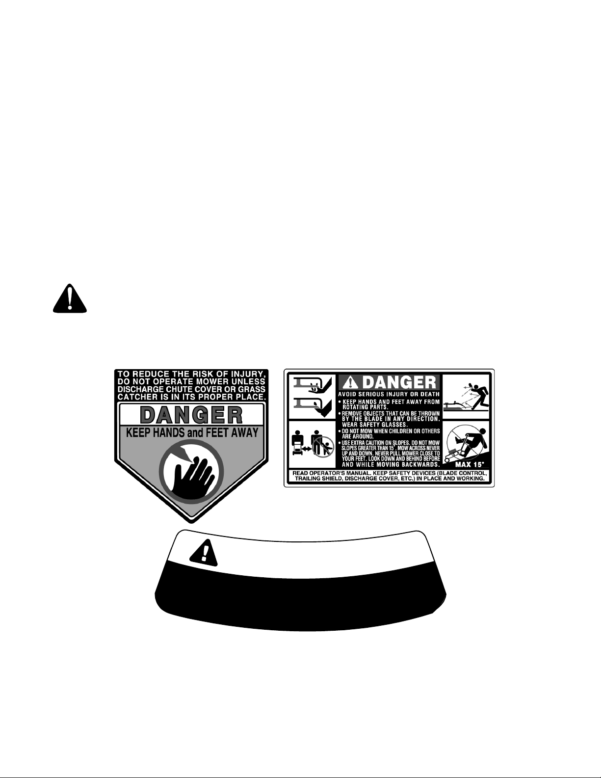
Warning — Your Responsibility: Restrict the use of this power machine to persons
who read, understand and follow the warnings and instructions in this manual and on the machine.
Three of the safety labels on your mower have been shown below in Figure 1. Please follow the
instruction on these labels and maintain safety.
• Never tamper with safety devices. Check their
proper operation regularly.
• After striking a foreign object, stop the engine,
remove the wire from the spark plug, and
thoroughly inspect the mower for any damage.
Repair the damage before starting and operating
the mower.
• Never attempt to make a wheel or cutting height
adjustment while the engine is running.
• Grass catcher components are subject to wear,
damage and deterioration, which could expose
moving parts or allow objects to be thrown. For
safety protection, frequently check components
and replace with manufacturer’s recommended
parts, when necessary.
• Mower blades are sharp and can cut. Wrap the
blade(s) or wear gloves, and use extra caution
when servicing them.
• Do not change the engine governor setting or
0
7
2
C
O
O
E
W
R
.
E
5
R
W
A
O
T
T
F
E
C
I
D
H
R
N
J
U
R
E
F
L
E
R
I
S
Figure 2
5
E
T
O
A
V
O
I
D
T
H
E
R
I
S
U
E
N
N
L
E
S
S
S
T
I
R
E
G
I
R
D
A
E
S
C
S
H
K
C
U
A
N
N
,
Y
T
C
N
I
E
O
I
E
V
,
R
S
T
I
N
O
R
U
M
R
P
L
O
P
C
G
A
R
E
P
H
R
E
P
M
E
T
G
U
L
A
L
P
Page 6
SECTION 2: SLOPE GAUGE
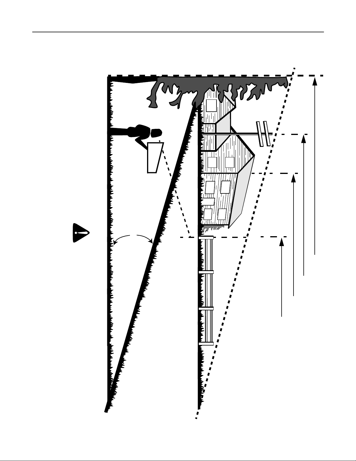
USE THIS PAGE AS A GUIDE TO DETERMINE SLOPES WHERE YOU MAY NOT OPERATE SAFELY.
Operate RIDING mowers up and down slopes, never across the face of slopes.
Operate WALK-BEHIND mowers across the face of slopes, never up and down slopes.
Do not mow on inc lines with a slop e in exces s of 15 degrees (a rise of appro ximately 2-1/2 fee t every 1 0 feet). A riding mower
could overturn a nd cause serio us injury. If o perating a walk- behind mower on such a sl ope, it is extremel y difficult to maintain
your footing and you could slip, resulting in serious injury.
F
O
L
D
O
N
D
O
T
T
E
S
E
R
P
E
R
E
D
L
I
N
E
,
A CORNER OF A BUILDING
SIGHT AND HOLD THIS LEVEL WITH A VERTICAL TREE
A POWER POLE
WARNING
15°
N
T
I
N
G
E
P
O
A
1
5
°
S
L
OR A FENCE POST
6
Page 7
SECTION 3: UNPACKING INSTRUCTIONS
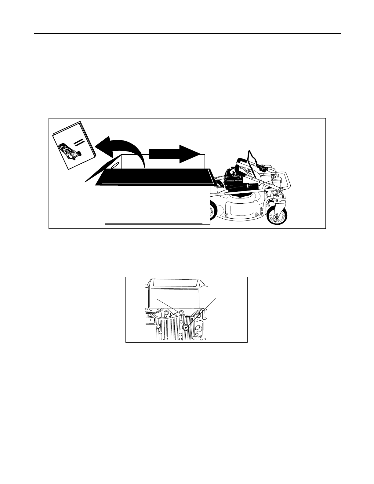
Remove Unit From Carton
• See Figure 3.
• Remove staples, break glue on top flaps, or cut tape at carton end and peel along top flap to open carton.
• Remove loose parts if included with unit (i.e., operator’s manual, etc.).
• Cut corner’s and lay carton down flat.
• Remove packing material.
• Roll or slide unit out of carton. Check carton thoroughly for loose parts.
l
a
u
n
a
M
s
’
r
o
t
a
r
e
p
O
REMOVE MANUAL & LOOSE PARTS
PUSH
Figure 3
Disconnect Spark Plug Wire
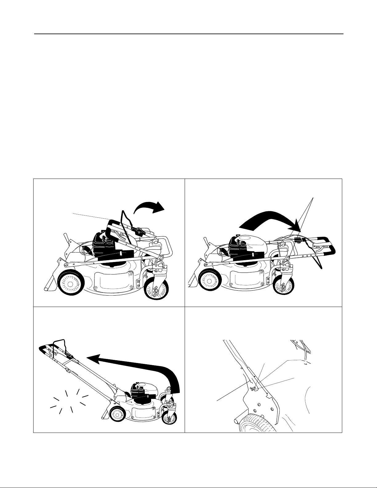
Before setting up your lawn mower, disconnect the spark plug wire from the spark plug, and ground it against the
engine by attaching rubber boot to a bolt or metal clip to the grounding post on the engine. See Figure 4.
Spark Plug Wire
Figure 4
Spark Plug
7
Page 8
SECTION 4: ASSEMBLING YOUR LAWN MOWER
This guide covers two model series. Models 950 thru 959 have fixed front wheels; models 960 thru 969 have caster
front wheels. All models are six speed, self propelled mowers. Much of this owner’s manual pertains to both models.
However, there are some model-specific information too. Use only the information appropriate for your mower
model.
Items Required F or Assembly
• Pair of Pliers (Not necessary, but helpful)
• Motor Oil
• Fresh Gasoline
IMPORT ANT :
engine with gasoline and oil as instructed in the separate engine manual before operating your mower.
NOTE: Reference to right or left hand side of the mower is observed from the operating position.
This unit is shipped WITHOUT GASOLINE in the fuel tank or OIL in the engine. Be certain to service
Setting Up Y our Lawn Mower
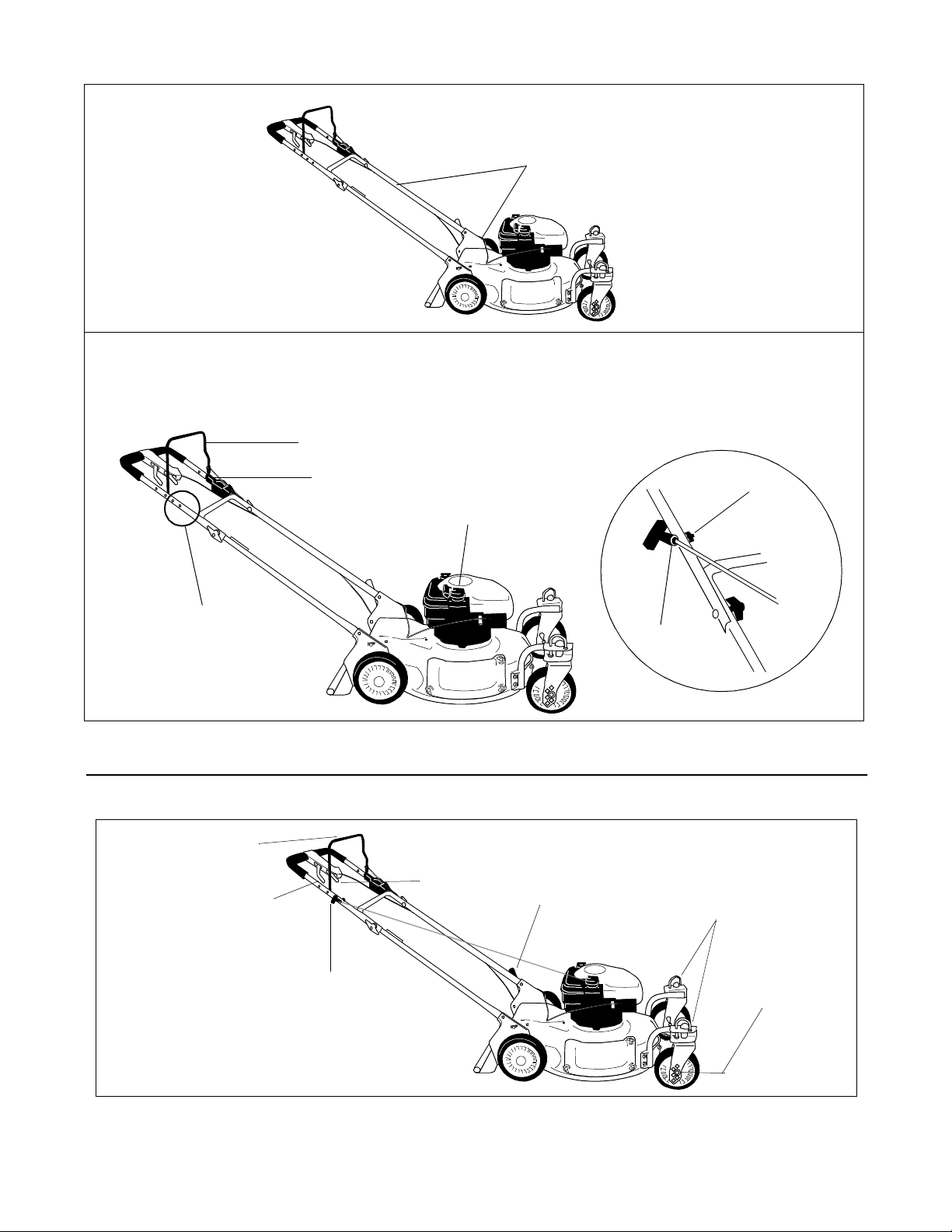
Follow steps 1 through 10 to set up your lawn mower.
Step 1. Lift upper handle. Align it with lower
handle.
Upper Handle
Step 2. Tighten w ing nuts
.
Here
Step 3. Raise complete handle assembly until it
clicks into place. Make sure not to kink
the control cables.
K
C
I
L
C
Step 4. Pinch lower handle against mounting
bracket with pliers.
Step 5. Move hairpin clip from outer to inner hole on
handle mounting bracket.
Inner Hole
Hairpin Clip
Pinch Here
8
Page 9
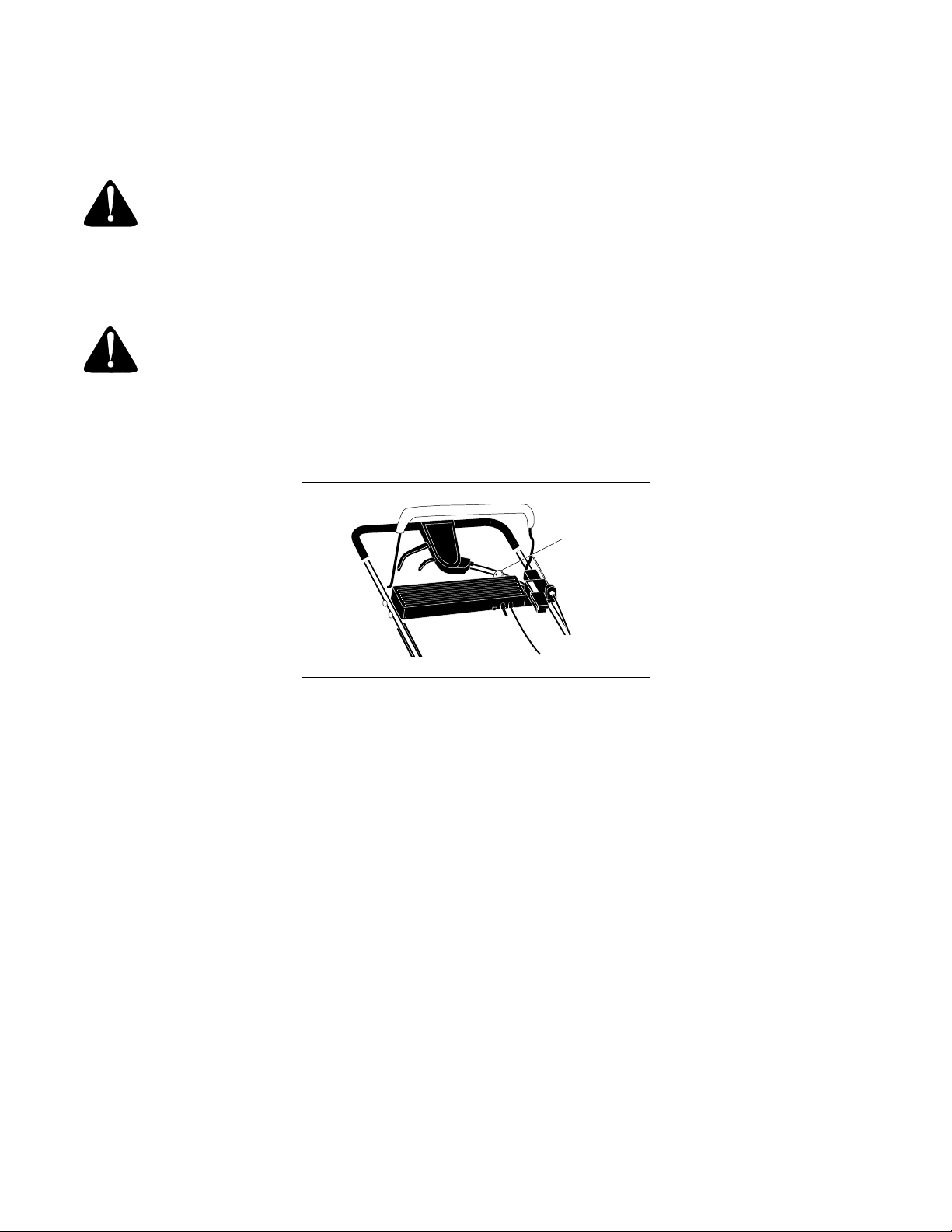
Step 6. Tighten the cable ties and insert pegs on ties in lower handle holes. Cut off excess.
Here
Step 7. Loosen the wing nut holding the rope guide to the upper handle.
Step 8. Squeeze the blade control handle against the upper handle and pull out starter rope slowly.
Step 9. Thread starter rope into rope guide.
Step 10. Tighten w ing nut.
Blade Control Handle
Look here
for rope
guide placement
Upper Handle
Starter Rope
Rope Guide
Wing Nut
• Your mower has been shipped in the lowest cutting position for shipping purposes. Please see the “cutting
height adjustment lever” section on page 10 of this owner’s guide to adjust cutting height.
SECTION 5: KNOW YOUR LAWN MOWER
Blade Control Handle
Drive Clutch Control
Shift Lever
Cutting Height
Adjustment Lever*
Front Wheel
Caster Locks
(969 only)
Recoil Starter
*Model 959 - adjusts all 4 wheels
Model 969 - adjusts rear wheels only
Front Wheel
Height Adjuster
(969 only)
Figure 5
9
Page 10
Blade Control Handle
The blade control handle is located on the upper handle of the mower. See Figure 5 . The blade control handle must
be depressed in order to start and operate the unit. Release the blade control handle to stop the engine and the
blade.
WARNING: The blade contro l handle is a safety dev ice. Never attemp t to bypass its opera tions. The
blade will be rotating whenever the engine is running.
Throttle Control
The throttle control is located on the engine. It is used to regulate the engine speed.
WARNING: The throttle control cannot be used to stop the engine. Do not adjust the throttle
control with the engine running.
Ignition Switch (Electric Start Unit Only)
The ignition switch is located on the left side of the handle panel. It is used for starting only. See Figure 6.
Ignition switch
Figure 6, Electric Start Unit Only
Recoil Starter
The recoil starter handle is attached to the upper handle. See Figure 5. Stand behind the unit in the operating
position to start the unit.
Drive Clutch Contr ol
Squeeze the drive clutch control to engage the drive system; release to disengage. Release the clutch control to
slow down when negotiating an obstacle, making a turn or stopping.
Shift Lever
The shift lever is located on the drive clutch control housing on the upper handle. See Figure 5. This lever is used to
select the forward speed of the mower. When changing mower speed, release the drive clutch control.
NOTE: Move the shift lever only when the engine is running. Changing the shift lever setting with the engine off can
cause damage to the mower.
Cutting Height Adjustment Lever (Model 950 Thru 959)
The cutting height adjustment lever is located above the left rear wheel. To adjust the cutting height, pull the lever
out and away from the mower. Then move it forward or back to the desired cutting height. See Figure 5.
10
Page 11

Cutting Height Adjustment Lever (Model 960 Thru 969)
The rear wheel cutting height adjustment lever is located above the left rear wheel. To adjust the cutting height, pull
the lever out and away from the mower. Move it forward or backward to the desired cutting height. See Figure 5.
The front wheel cutting height is determined by the selection of one of six positions in each caster assembly.To
adjust, remove the wing nut from the axle bolt. Slide the axle bolt and spring washer from the assembly and select a
cutting height. With the spring washer placed on the axle bolt, reinsert the axle bolt in the square hole desired,
through the wheel assembly, and secure with the wing nut previously removed. Remember that higher the position,
lower the cut.
IMPORT ANT :
height of your mower. This will help stop scalping.
All wheels must be placed in the same relative position. For rough or uneven lawns, raise the cutting
Caster Lock (Models 960 Thru 969)
Warning: When operating mower on hills, front wheels should be locked in the straight ahead position.
The casters can be locked in a straight ahead position or can be left to swivel freely. Lift and place the lock pins in
the larger holes for locked, straight ahead operation, place pins in smaller holes to allow casters to rotate freely.
Engine Controls
See the engine manual for the location and function of the controls located on the engine.
SECTION 6: OPERATING YOUR LAWN MOWER
Warning: Keep hand s and feet away fr om the chute area on the cuttin g deck. See Secti on 4. The
operation of any la wn m owe r ca n r esu lt i n foreign objects bei ng thr own i nto the ey es, wh ic h can r es ul t i n
severe eye damage. Always wear safety glasses or eye shields.
NOTE: Fo r best results raise the cutting position until it is determined which height i s best for your lawn. See
CUTTING HEIGHT ADJUSTMENT LEVER in the CONTROLS section.
Gas And Oil Fill Up
Service the engine with gasoline and oil as instructed in the separate engine manual. Read all instructions carefully.
Warning: Never fill fuel tank indoors, with engine running or until the engine has been allowed t o
cool for at least two minutes after running.
Each Time Before You Start Your Mower
Electric Start Units Only:
Warning: The battery contains corrosive fluid and toxic material—HANDLE WITH CARE. Keep
away from children. D o not puncture, disassemble , mutilate or incinerate the battery. Explosive gases
could be vented during charging or discharging. Use in a well ventilated area, away from sources of
ignition.
Charging Instructions
Charge battery for 16 hours before initial use. Do not charge longer than 20 hour s.
IMPORT ANT :
Use only the battery charger supplied with this mower.
11
Page 12
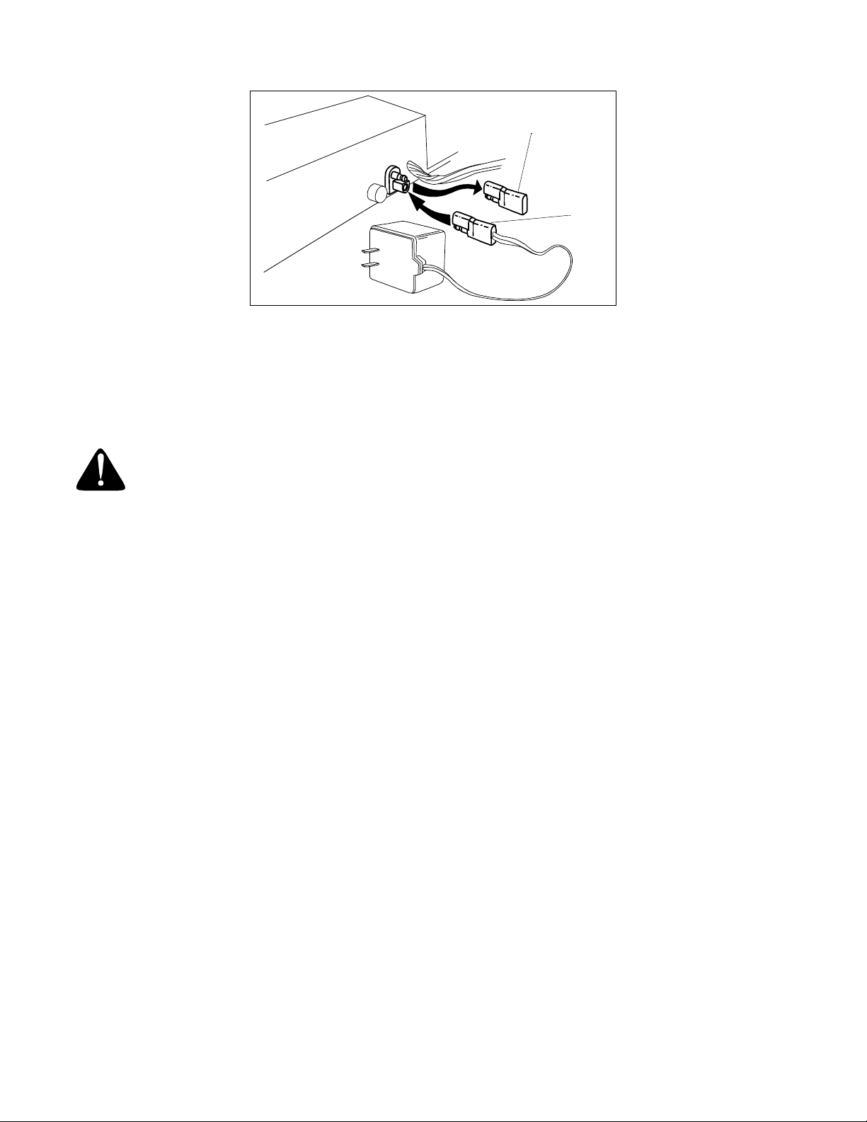
Protective cap
Battery
pack
lead
Figure 7
To charge the battery, remove the protective cap from the end of the battery pack lead. Plug charger lead into
battery pack lead and then insert battery charger plug into 120 volt standard household outlet. See Figure 7. Follow
this order of action every time you charge the battery.
After charging, disconnect battery charger plug from household outlet first, then disconnect charger lead from
battery pack lead.
Warning: Do not remove the battery pack from the handle panel for any reason other than
replacement. When replacing the battery pack, refer to the instructions in the maintenance section.
All Units:
• Attach spark plug wire to spark plug. Make certain the metal cap on the end of the spark plug wire is fastened
securely over the metal tip on the spark plug.
• Check for proper drive clutch operation using the NEUTRAL ADJUSTMENT TEST.
Neutral Adjustment Test
To perform the NEUTRAL ADJUSTMENT TEST answer the following questions.
• With the drive clutch control released, push mower forward and pull it backward. Does it move freely?
• Squeeze the drive clutch control and pull the mower backward. Do the rear wheels lock (not turn)?
• Is the drive clutch control cable free of kinks or sharp bends?
If you answered “yes” to all three questions, your mower passed the test and you can start your mower. If you
answered “no” to any of the three questions, you need to adjust the drive clutch control following instructions on 14
of this book.
To Start Engine And Engage Blade
• Move the throttle control lever on the engine to the fast (rabbit) position.
• Prime or choke engine as instructed in the engine manual.
• Stand behind the unit, squeeze and hold the blade control handle against the upper handle.
• Electric Start: Turn the ignition key to the right to start the engine. Release the key after the engine starts.
• Recoil Start: Grasp starter handle and pull rope out slowly until engine reaches start of compression cycle
(rope will pull slightly harder at this point). Let the rope rewind slowly. Pull rope with a rapid, continuous, full arm
stroke. Keep a firm grip on starter handle. Return it slowly to the rope guide.
• After engine starts, move throttle control to desired engine speed. (The mower is designed to be operated at full
throttle.)
NOTE: If any problems are encountered, refer to the TROUBLE SHOOTING Section of this manual.
12
Page 13
To Stop Engine And Blade
• Release the blade control handle to stop the engine and the blade.
WARNING: The blade continues to rotate for a few seconds after the engine is shut off.
Using Y our Rotary Mower
Be sure that the lawn is clear of stones, sticks, wire, or other objects which could damage the lawn mower or engine.
Such objects could be accidently thrown by the mower in any direction and cause serious personal injury to the
operator and others.
For best results, do not cut wet grass because it tends to stick to the underside of the mower, preventing proper
discharge of grass clippings, and could cause you to slip and fall. New grass, thick grass or wet grass may require a
narrower cut.
For a healthier lawn, never cut off more than one-third of the total length of the grass. Your lawn should be cut in the
fall season as long as there is growth.
This mower is designed to be operated at full throttle to give you the best cut and do the most effective job of mowing
or mulching.
Warning: If you strike a foreign object, stop the engine. Remove wire from the spark plug,
thoroughly inspect the mower for any damage, and repair the damage before restarting the mower.
Extensive vibration of the mower during operation is an indication of damage. The unit should be
promptly inspected and repaired.
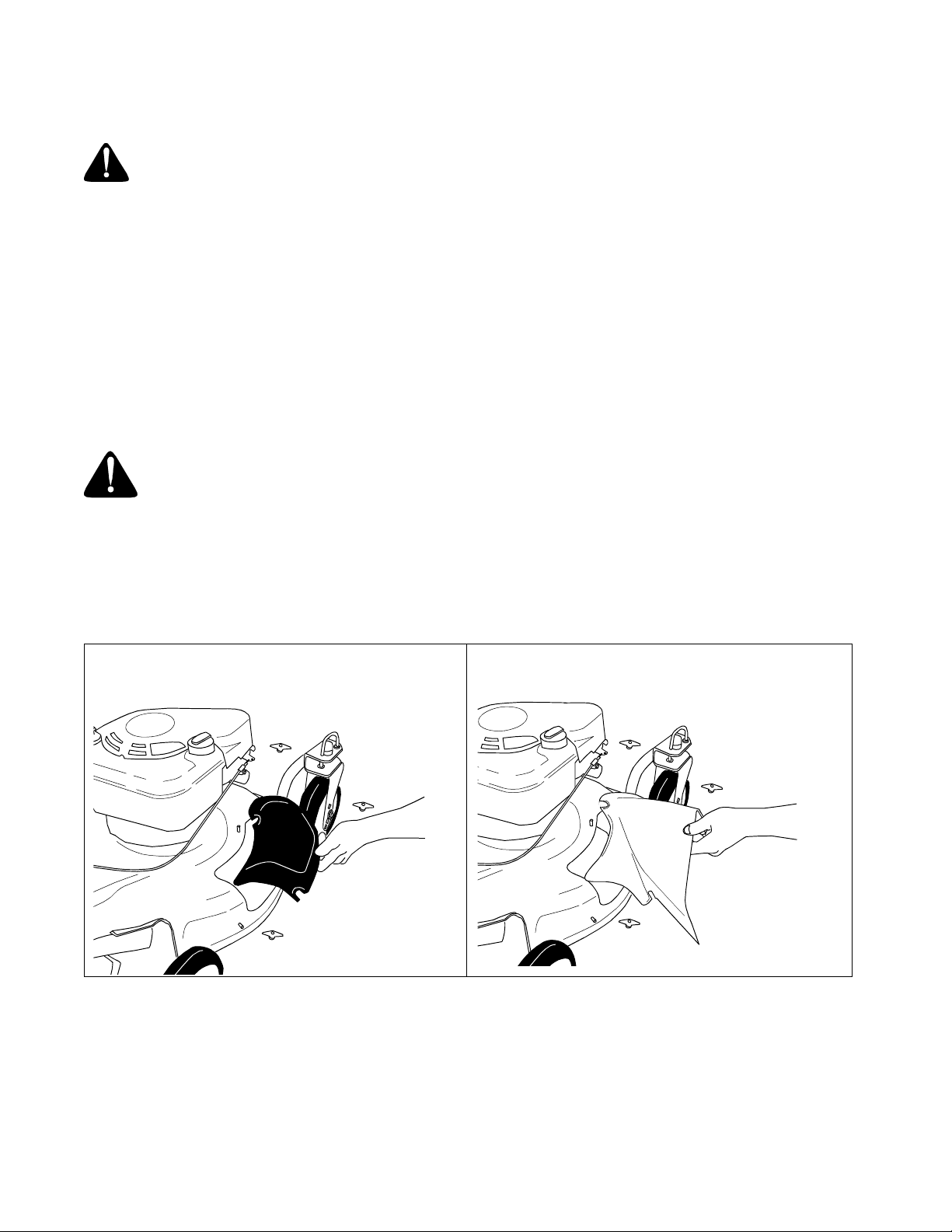
Side Discharge Grass Clippings
This mower can side discharge grass clippings. Follow steps 1 and 2 to ready this mower for side discharge
operation.
Step 1. Remove three plastic wing nuts and
mulching cover.
Step 2. Replace with side discharge chute and
three plastic wing nuts.
13
Page 14
SECTION 7: MAKING ADJUSTMENTS
Warning: Do not at any time make any adjustment to lawn mower without first stopp ing engine and
disconnecting spark plug wire.
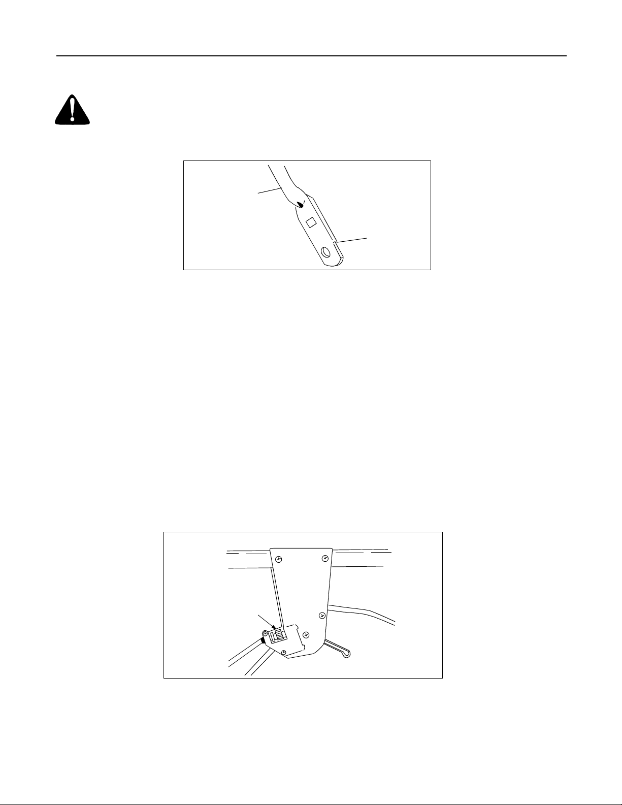
Handle Height Adjustment
Lower Handle
Notch
Figure 8
Your mower is shipped with the handle in the higher height position. To lower the handle height, proceed as follows.
• Remove the start er ro pe fr om the rope guide .
• Remove the upper handle by removing the hand knobs and carriage bolts. Lay the upper handle out of the way
being careful not to bend or kink the cables.
• Remove the hairpin clips from the weld pins on the handle brackets. Press out on the legs of the lower handle.
Remove the lower handle from the mower.
• Turn the lower handle around so that the notch on the bottom of the lower handle is facing forward as shown in
Figure 8. Reassemble placing the bottom holes in the handle over the weld pins in the handle mounting bracket.
• Reassemble the upper handle to the lower handle.
• Place the hairpin clips in the inner holes in the weld pins and attach the starter rope as instructed in the Set-Up
Instructions.
Drive Clutch Control Adjustment
The drive clutch control adjustment wheel is located in the drive clutch control handle housing and is used to tighten
or loosen the drive belt. You will have to adjust the drive clutch control if any of the following happens:
• The mower does not propel itself with the drive clutch engaged.
• The mower’s drive wheels hesitate with the drive clutch engaged.
To resolve the above problems, rotate the adjustment wheel with your fingers—clockwise to tighten the cable and
counter-clockwise to loosen the cable. See Figure 9.
Bottom View
Adjustment wheel
Figure 9
NOTE: For some operators, the drive clutch handle may not be in a comfortable position. You can adjust the handle
by tightening or loosening the adjustment wheel.
14
Page 15
Shift Lever Cable Adjustment
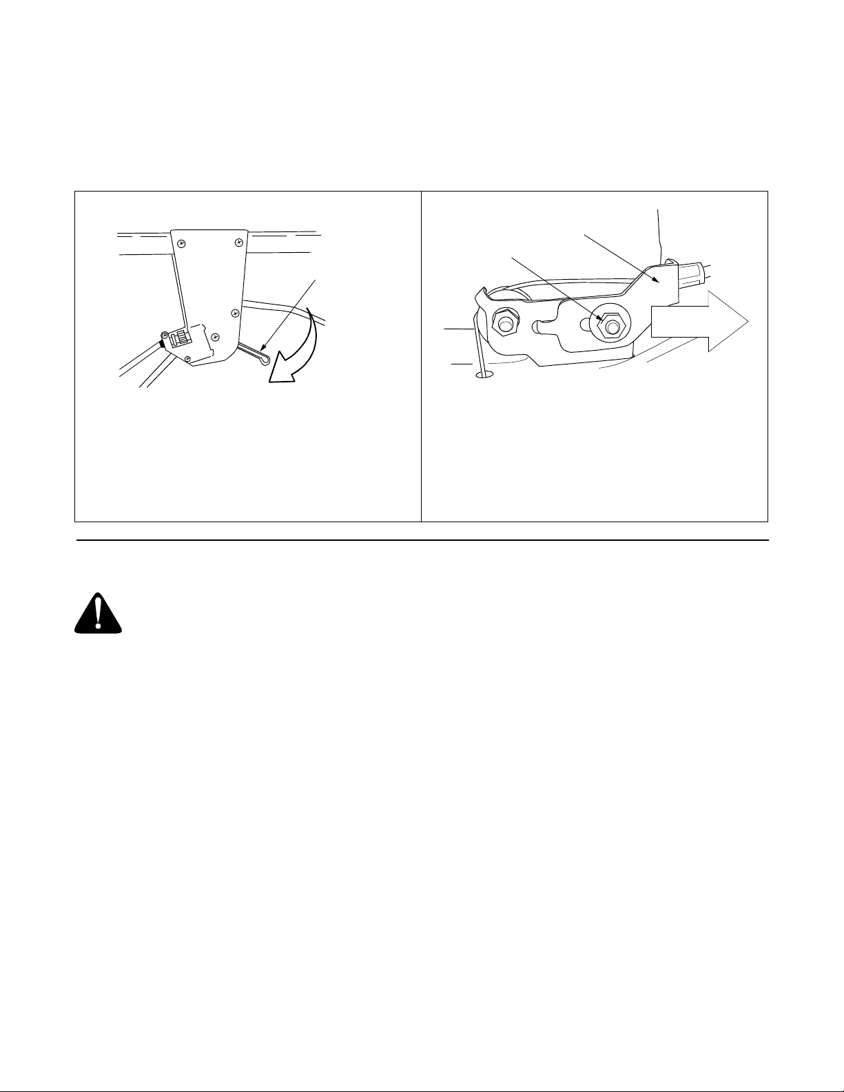
Periodic adjustment of the six-speed shift cable may be required due to normal wear on the cable. Adjustment is
needed if all six speeds do not work.
The adjustable cable bracket is located beside the engine on the left side of the mower. Follow steps 1 through 7 to
adjust the shift lever
.
Bottom View
Speed Control
Lever
Step 1. Start engine.
Step 2. Place speed control in the sixth speed
position.
Step 3. Stop engine.
Step 4. Disconnect spark plug wire and ground it.
Hex Nut (A)
Step 5. Loosen hex nut (A) which secures the
Step 6. Push back on the adjustable cable bracket.
Step 7. Tighten hex nut (A).
Adjustable Cable Bracket
adjustable cable bracke t.
SECTION 8: MAINTAINING YOUR LAWN MOWER
WARNING: Be sure to disconnec t and ground the spark plug wire before perfo rming any repairs or
maintenance.
PUSH
NOTE: When tipping the unit, empty the fuel tank and keep the engine spark plug side up. Never tip the mower more
than 90 degrees and do not leav e the mower tippe d for an y len gth of tim e. Oil can dr ain i nto the upper part o f the
engine causing a starting problem.
Engine
Refer to the separate engine manual for all engine maintenance instructions.
• Maintain engine oil as instructed in the separate engine manual packed with your unit. Read and follow
instructions carefully.
• Service air cleaner every 25 hours under normal conditions. Clean every few hours under extremely dusty
conditions. Poor engine performance and flooding usually indicates that the air cleaner should be serviced. To
service the air cleaner, refer to the engine manual packed with your unit.
• The spark plug should be cleaned and the gap reset once a season. Spark plug replacement is recommended
at the start of each mowing season; check engine manual for correct plug type and gap specifications.
• Clean the engine regularly with a cloth or brush. Keep the cooling system (blower housing area) clean to permit
proper air circulation which is essential to engine performance and life. Be certain to remove all grass, dirt and
combustible debris from the muffler area.
15
Page 16
Deck
The underside of the mower deck should be cleaned after each use to prevent a build-up of grass clippings, leaves,
dirt or other matter. If this debris is allowed to accumulate, it will invite rust and corrosion, and may prevent proper
mulching, discharge or bagging.
The deck may be cleaned by tilting the mower and scraping clean with a suitable tool (make certain the spark plug
wire is disconnected before starting to clean).
Electric Start Units Only:
Battery Pack Replacement
Remove the battery pack from the handle panel for replacement only. Do not separate the batteries for any reason.
Dispose of ba tterie s proper ly.
Warning: Batteries contain sulfuric acid which may cause burns. Do not short circuit or mutilate
batteries in any way. Do not put batteries in fire as these may burst or release toxic materials.
When replacing battery pack in handle panel, battery pack must be positioned with the positive terminal to the right
hand side and the negative terminal to the left hand side of panel. Replacing the battery pack incorrectly will cause
serious damage. The positive lead on the wire harness has the smaller connector. Connect the positive lead to the
positive side of the battery pack, then connect the negative side.
In-line Fuse
The unit is equipped with an in-line fuse. If the unit fails to start, check the fuse inside the battery cover by turning the
end of the fuse holder and removing from the battery cover. Replace with standard automotive 7-1/2 amp fuse.
Storage Of The Battery
The battery must be stored with a full charge. A discharged battery will freeze.
IMPORT ANT :
service. Refer to charging instructions in OPERATION section.
All batteries discharge during storage. Recharge battery every two months and before returning to
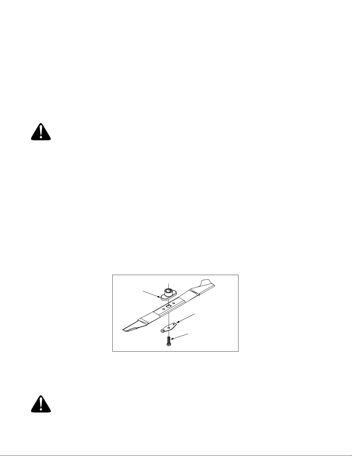
Cutting Blade Removal, Replacement And Sharpening
Blade
Adapter
Blade Bell
Support
Hex Bolt
Figure 10
• When removing the cutting blade for sharpening or replacement, protect your hands by using heavy gloves or a
rag to handle the blade.
• Remove the bolt and the blade bell support which hold the blade and the adapter to the engine crankshaft.
• Remove the blade and the adapter from the crankshaft.
Warning: Periodically inspect the blade adapter for cracks, especially if you strike a foreign object.
Replace when necessary.
16
Page 17
When sharpening the blade, follow the original angle of grind as a guide. It is extremely important that each cutting
edge receives an equal amount of grinding to prevent an unbalanced blade. An unbalanced blade will cause
excessive vibration when rotating at high speeds. It may cause damage to the mower, and it could break causing
personal injury.
The blade can be tested by balancing it on a round shaft screwdriver. Remove metal from the heavy side until it
balances evenly. It is recommended that the blade be removed from the adapter when testing for balance.
Before reinstalling the blade and the blade adapter to the unit, lubricate the engine crankshaft and the inner surface
of the blade adapter with light oil.
• Be sure to install the blade with the side of the blade marked “Bottom” (or with part number) facing the ground
when the mower is in the operating position.
• Slide the blade adapter onto the engine crankshaft.
• Place the blade on the adapter. Be certain the blade is aligned with and seated onto the blade adapter flanges.
• Place the blade bell support on the blade. Make sure the notches on the blade bell support are aligned with the
small holes in the blade.
• Replace hex bo lt.
• Tighten hex bolt to torque: 450 in. lbs. min., 600 in. lbs. max.
NOTE: To ensure safe operation of your unit, the blade bolt must be checked periodically for correct torque.
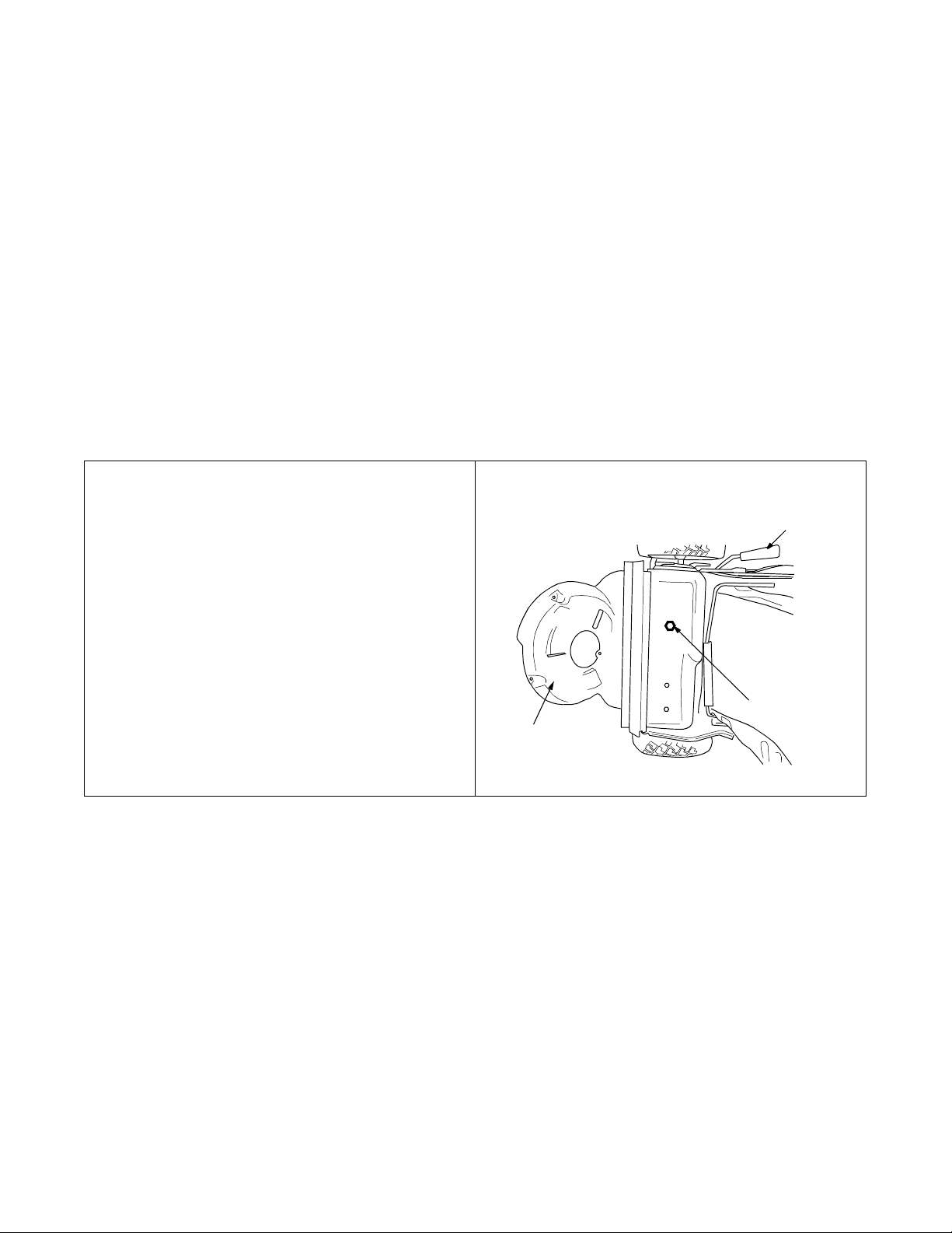
Drive Belt Removal And Replacement
Step 1. Disconnect the spark plug wire and ground
it against the engine.
Step 2. Drain the fuel tank or place a piece of
plastic beneath the cap to prevent gasoline
leakage.
Step 3. Place shift lever in the first position.
Step 4. Tip the mower on its side. Block securely.
Step 5. Remove the center bolt which secures the
blade to the crankshaft. Remove the
blade, and the blade adapter, wave
washer, and spacer. Refer to Cutting
Blade Removal, Replacement and
Sharpening in the Maintenance Section.
Step 6. Move rear height adjuster to the sixth
position.
Step 7. Remove the hex bolt holding the
transmission to the mower housing.
Rear Height Adjustment Lever
Hex Bolt
Baffle
17
Page 18
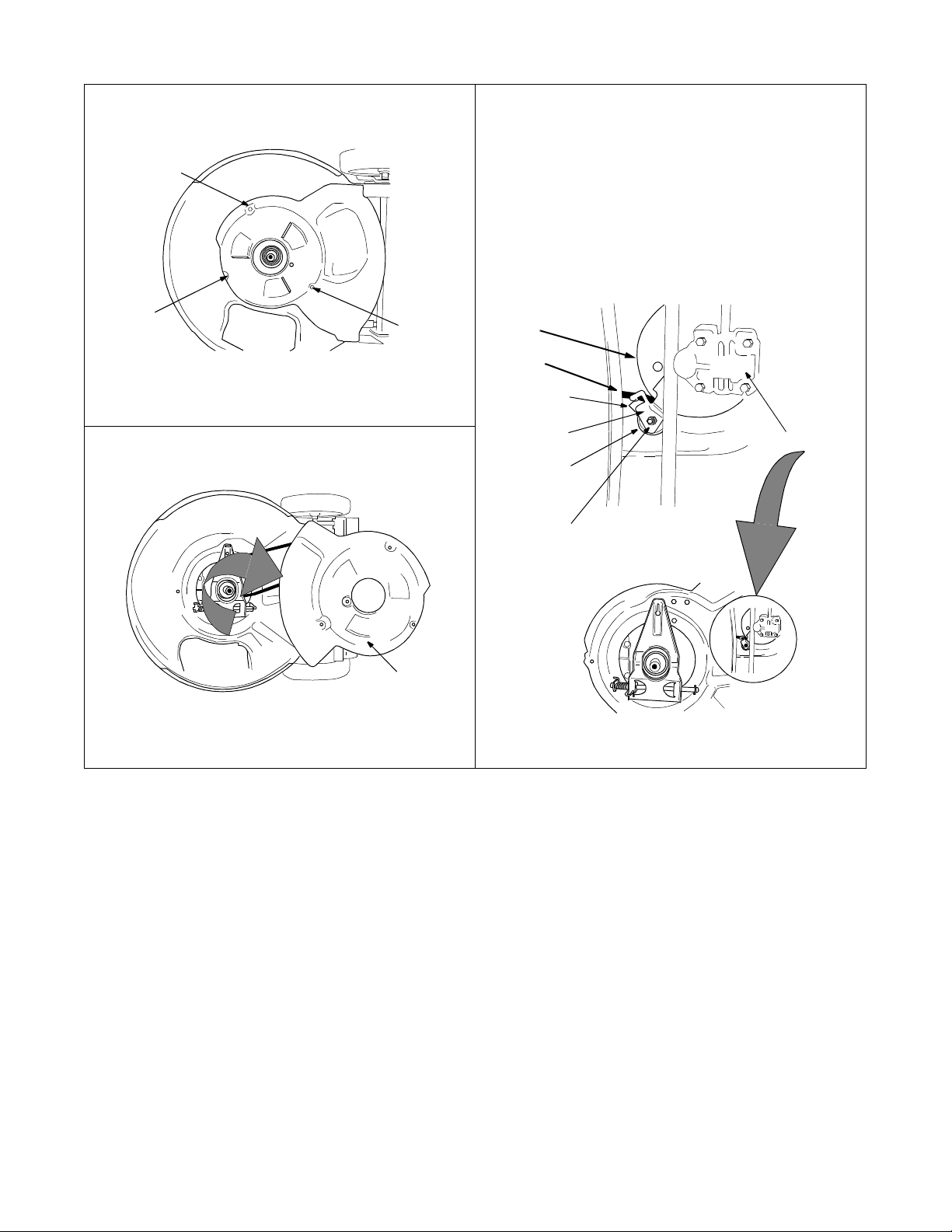
Step 8. Using a 3/8” socket, remove three hex
screws holding the baffle to the deck.
Hex Screw
Step 9. Tilt the transmission forward and loosen
the idler pulley bolt and locknut 1/2 turn
using two 7/16” wrenches.
Step 10. Using a pair of pliers, pull back and rotate
belt keeper bracket from the slot on idler
pulley.
Step 11. Slide the belt out from between the Belt
Keeper Bracket and the idler pulley.
Hex Screw
Hex
Screw
Step 12. Pivot baffle towards the rear of the mower.
Baffle
Transmission
Pulley
Belt
Belt Keeper
Bracket
Idler Pulley
Bracket
Idler Pu lley
Bolt and
Locknut
Transmission
18
Page 19
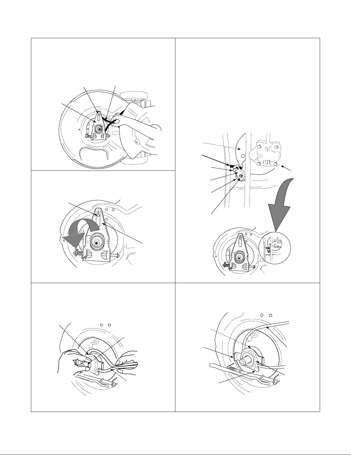
Step 13. Squeeze the belt together and push belt
forward. Press the control arm inward
towards the deck and remove the six
speed cable from the slot.
Six-Speed
Cable Slot
Belt
Control
Arm
Step 18. Pivot the control arm down away from the
pulley and belt.
Six-Speed
Cable Slot
Step 14. Place the new belt over the transmission
pulley. Start the belt in pulley groove and
rotate pulley until belt is seated in
transmission pulley.
Step 15. Place belt between idler pulley and the belt
keeper bracket.
Step 16. Using pliers, rotate the belt keeper bracket
so that it snaps into slot on the idler
bracket.
Step 17. Tighten the idler pulley bolt and locknut
1/2 turn using two 7/16” wrenches.
Transmission
Pulley
Belt
Belt Keeper
Bracket
Idler Pulley
Bracket
Idler Pulley
Bolt and
Locknut
Transmission
Control
Arm
Step 19.
Step 20. Lift off the lower pulley assembly and
remove the old belt from around the
crankshaft.
Lower Pulley
Half
Crankshaft
Belt
Step 21. Place belt between the two pulley halves
on the crankshaft. Make sure to route the
belt inside the belt guard pin.
Upper
Pulley
Half
Tab
Belt
Guard
Pin
Belt
Lower
Pulley
Half
Step 22. When changing the belt, do not
disassemble the lower pulley assembly.
19
Page 20
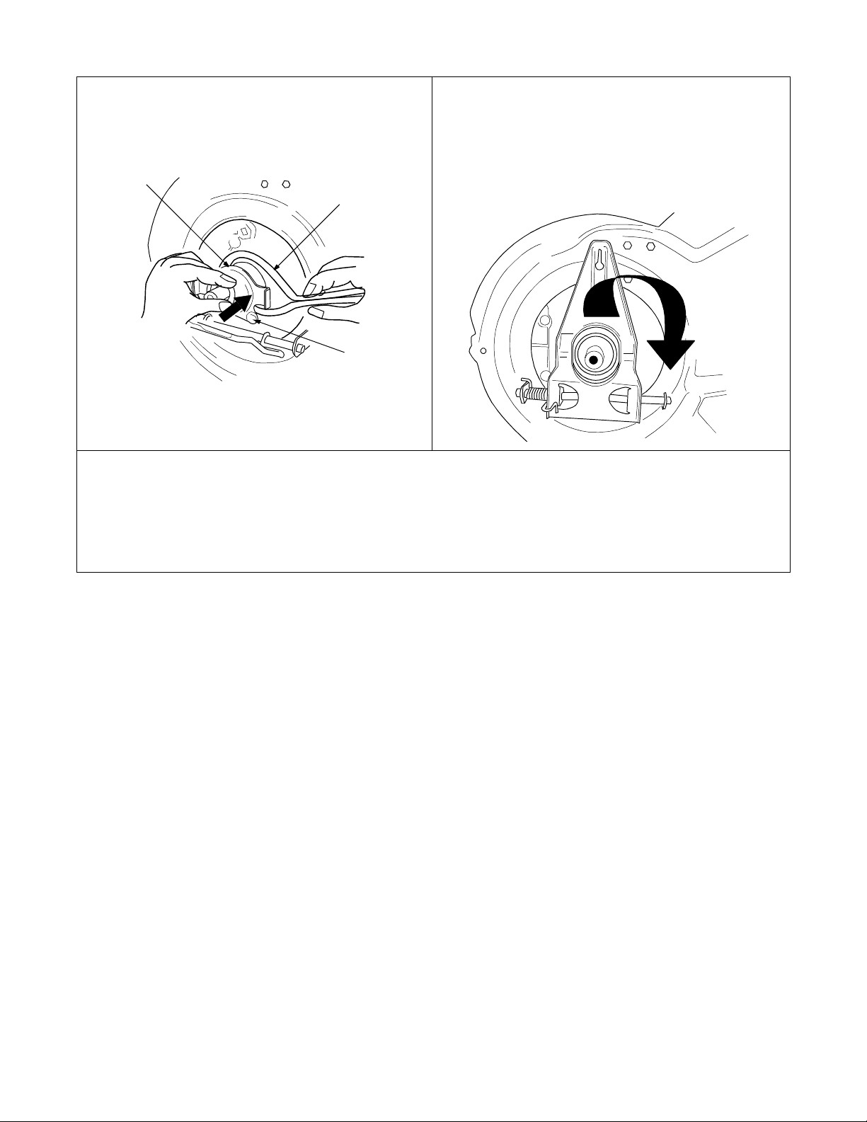
Step 23. Pinch belt together so that it is not in the
pulley groove, and the lower pulley can be
pushed towards the engine.
Step 24. Pivot the control arm back to its original
position and reinstall the six-speed cable
into the slot.
Step 25. Check and make sure the belt is routed
Lower Pulley
Half
Belt
Belt
Guard
Pin
inside the pulley halves and the belt guard
pin.
Step 26. Reinstall the bolt securing transmission to rear mower housing.
Step 27. Pivot the baffle back to its original position and secure with three hex screws earlier removed. You
will need a 3/8” socket for these screws.
Step 28. Lightly lubricate the inside of the blade adapter and reinstall spacer, wave washer, blade adapter
assembly and the blade in the correct order.
Step 29. Tighten the hex bolt to secure the blade. Follow recommended torque which is 450-600 in. lbs.
20
Page 21
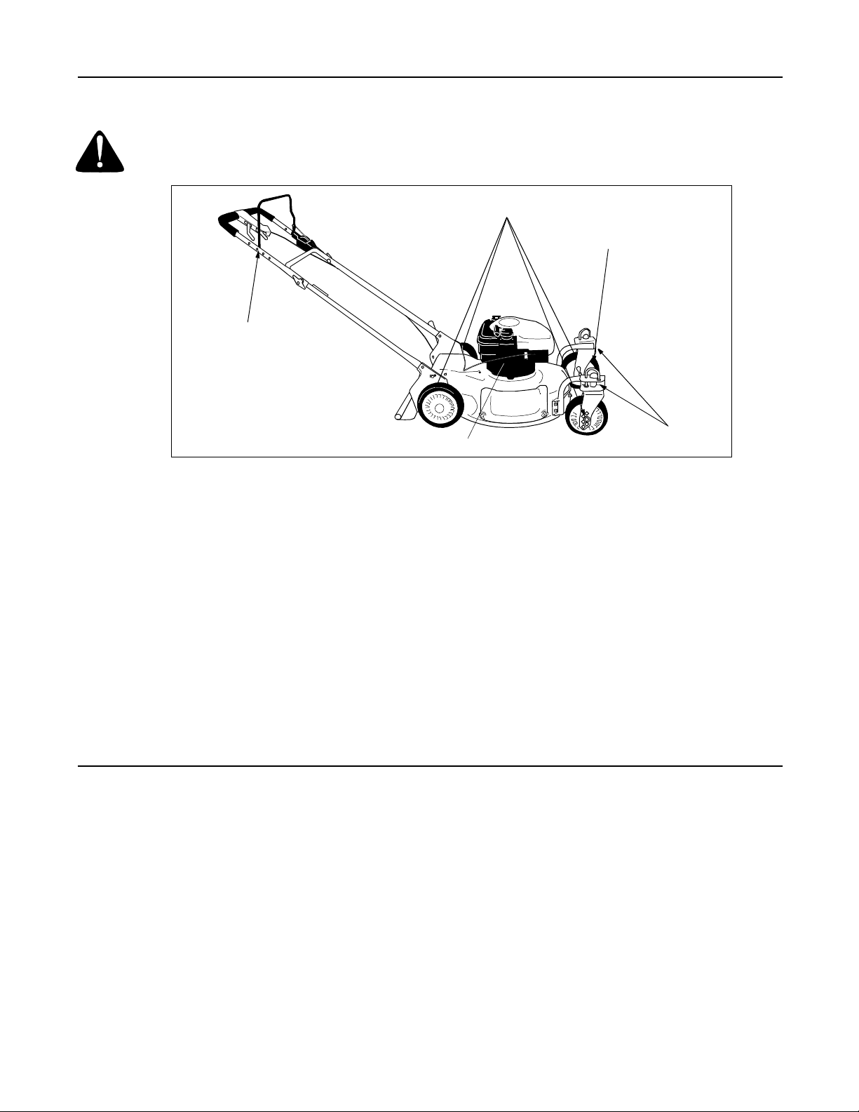
SECTION 9: SERVICE
WARNING: Always stop e ngine and disconnec t spark plug wire be fore cleaning, lubr icating or doing
any kind of work on the lawn mower.
Blade Control
Handle
LUBRICATE
Wheels
SEE ENGINE MANUAL
Figure 11
Caster Assembly
Blade Control
Lubricate the pivot points on the blade control handle and the brake cable at least once a season with light oil. See
Figure 11. The blade control must operate freely in both directions.
Wheels
Lubricate the wheel at least once a season with light oil (or engine oil). Also, if the wheels are removed for any
reason, lubricate the surface of the axle bolt and the inner surface of the wheel with light oil. See Figure 11.
Caster Assembly (960-969 Only)
Grease fittings are provided for easy lubrication of the swivel pins located on the front caster assembly.
Engine
Follow engine manual for lubrication instructions.
SECTION 10: OFF-SEASON STORAGE
The following steps should be taken to prepare lawn mower for storage.
• Clean and lubricate mower thoroughly as described in the lubrication instructions.
• We do not recommend the use of pressure washers or garden hose to clean your unit. They may cause damage
to electric components, spindles, pulleys, bearings or the engine. The use of water will result in shortened life
and reduce serviceability.
• Refer to engine manual for correct engine storage instructions.
• Coat mower’s cutting blade with chassis grease to prevent rusting.
• Follow battery storage instructions on 16 (Electric Start Units Only).
• Store mower in a dry, clean area. Do not store next to corrosive materials, such as fertilizer.
NOTE: When storing any type of power equipment in an unventilated or metal storage shed, care should be taken to
rust-proof the equipment. Using a light oil or silicone, coat the equipment, especially cables and all moving parts.
21
Page 22

SECTION 11: TROUBLE SHOOTING GUIDE
Trouble Possible Cause(s) Corrective Action
Engine fails to start Blade control han dle disenga ged.
Spark plug wire disconnected.
Throttle control lev er not in correct
starting position.
Fuel tank empty , or stal e fuel.
Blocked fuel line.
Faulty spark plug.
Engine flooded.
Engine runs erratic Unit running in START position.
Spark plug wire loose.
Blocked fu el line or stale fuel .
V ent in gas cap plugge d.
Water or d irt in fuel system.
Dirty air cleaner.
Carburetor out of adjustment.
Engine ov erheats Engine oil le ve l low .
Air flow restricted.
Carburetor not adjusted properly .
Occasional skip (hesit ates)
at high speed
Idles poorly Spark plug fou led, f aulty or gap too
Excessive vi bration Cutting bla de loose o r unbalanced .
Mower will not mulc h grass Engine speed too low .
Uneven cut Wheels not posi tioned correc tly.
Spark plug gap too close. Adjust gap to.030”.
wide.
Carburetor impro perly adjusted .
Dirty air cleaner.
Bent cutting blade.
Wet grass.
Excessively high gr ass.
Dull blade .
Dull blade .
Refer to separate engine manual packed with your mower for more engine related information.
Engage blade control hand le.
Connect wire to spark p lug.
Move throttle le ver to FAST or ST AR T position.
Fill tank with cle an, fresh gasol ine.
Clean fuel line .
Clean, adjust gap or replace.
Crank engine wi th throttle in F AS T position.
Move thr ottle lev er to FAST position.
Connect and tighten spark plug wire .
Clean fuel line; fi ll tank with clean, fresh
gasoline.
Clear vent.
Drain fuel tank. Refill wi th fresh fuel .
Clean air cleaner.
Adjust carb uretor .
Fill crankcas e with proper o il.
Remove b low er housing a nd clean .
Adjust carb uretor .
Reset gap to.030” or replace spark plug.
Adjust carb uretor .
Clean air cleaner.
Tighten blade and adapter. Bala nce blade.
Replace blade .
Run at full throttle.
Do not mow when grass is wet; wait until
later to cut.
Mow once at a high cut ting height, then
mow again at desired height or make a narrower cutting s wa th (1/2 widt h).
Sharpen or replace bla de.
Place all f our wheels in same heig ht position.
Sharpen or replace bla de.
NOTE: For repairs beyond the minor adjustments listed above, contact your nearest authorized service dealer or call
1-800-94WHITE.
22
Page 23
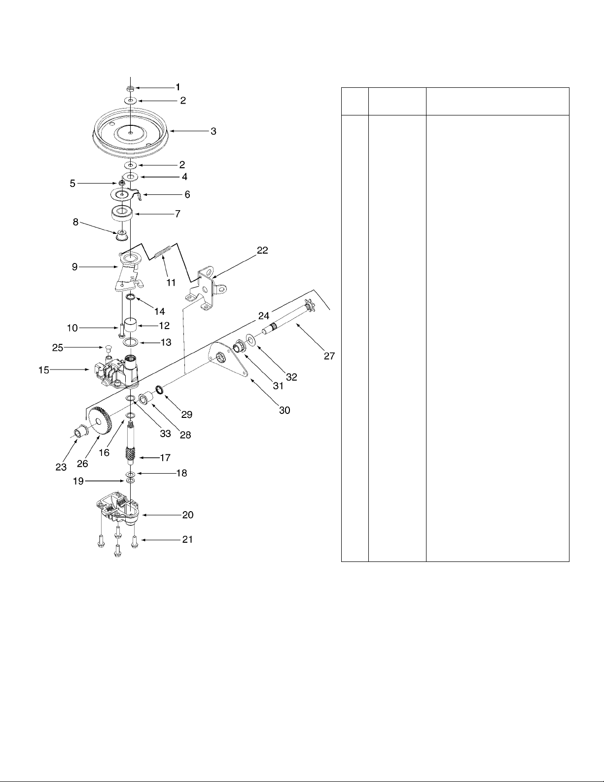
Models 950 thru E969
Ref.
No.
1 712-3025 Hx. Jam Nut 5/16-24
2 736-0425 Bell Wash. .325 x .930 x .045
3 756-0656 Pulley
4 736-3084 Fl. Wash . .510 x 1.1 20 x .06 0
5 712-0896 Hx. Jam Nut 1/4-28
6 782-7598 Belt Keeper
7 741-0600 Bearing
8 750-1050 Flange Spacer
9 682-0027A Idler Bracket Assembly
10 710-0299 Hx. Cap Scr. 1/4-28 x 1.00 Gr . 5
11 732-0849A Extension Spring
12 741-0682A Bearing Sleev e
13 736-0570 Fl. Wash. .885 x 1.1 45 x.030
14 721-0329 Oil Seal
15 618-0253 Upper Housing Assembly
16 736-0616 Thrust Wash. .504 x .70 0 x .030
17 717-1487 Pinion Shaft 10 T.
18 736-0314 Thr. Wash . 3/8 x .70 x .030
19 736-0569 Thr. Wash . .388 x .625 x .062
20 618-0252 Lower Housing Assemb ly
21 710-0642 Hx. Scr. 1/2-20 x .75
22 782-7601A Cable Brac ket
23 741-0674 Bearing
24 611-0066 Shaft Assembly
25 721-0325 Plug
26 717-1469 Gear 34 T .
27 711-1168 Output Shaft 6 T.
28 741-0673 Flange Bearing
29 721-0329 Oil Seal
30 782-7595 Pivot Bracket
31 741-0324 Flange Bearing
32 736-0369 Wash. Fl. .508 I.D . x 1.00 O .D. x
33 741-0690 Bearing
- 618-0263A Transmission Complete
Part No. Description
.020
23
Page 24
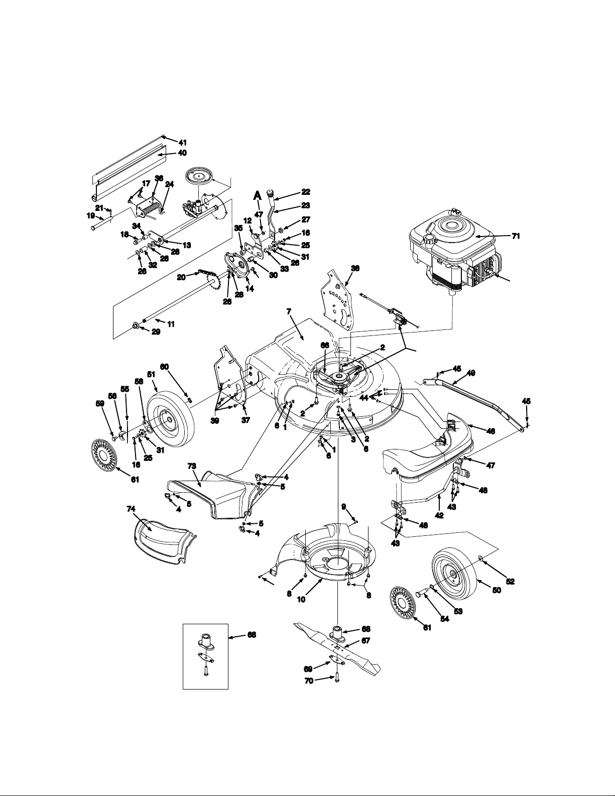
Models 950 thru 959
Transmission and pulley
for reference only
8
Pulley Assembly for
reference only
72
15
24
Page 25

Models 950 thru 959
Ref.
No.
1 710-0134 Scr . Carr . 1/4-20 x .62
2 710-0654A Scr. TT :3/8-18:1 .00
3 710-0703 Scr . 1 /4-20 x .750
4 712-0397 Wing Nut 1/4-20
5 726-0233 Nut, Pu sh .25 I.D. x .50 O.D .
6 736-0204 W ash. F l. .334 I .D .x .62 x .03
7 782-0046A-0662 Deck - 21”
8 710-0653 Scr. TT. 1/4-20 x .375
10 731-1828 Baffle
11 638-0012 Rear Axle Ass’y
12 682-0531 Pivot Arm Ass’y
13 682-7526 T rans . Axle Ass ’y
14 682-7528 Chain Cover Ass ’y
15 710-0969 Scr., Truss Machine TT 1.0”
16 710-0751 Cap Screw HH 1/4-20 x .6 20
17 710-0896 Scr., AB 1/4-14 x .825
18 710-1315 Scr., 3/8 116 x .25
19 711-0835 Clevis Pin .50 Dia. x 4.82 L g.
20 713-0453 Chain-Endls. #48 .500 P x 24L
21 714-0474 Cotter Pin .125O.D . x .75
22 720-0223 Grip
23 732-0803A Spring Lever
24 732-0832 T orsi on Spring
25 736-0270 Bell Wash. .285 x .75 x .082
26 736-0369 Fl. Wash..508 I.D . 1.000 x.0 20
27 738-0529 Nut Shld. .825 Dia. x .165 Lg.
28 741-0324 Hx.Flg. Brg..506 I.D . x .590 L.
29 741-0522 Hx.Flg. Brg. .506 I.D . x.715 L.
30 741-0978 Hx. Slv. Brg..504 I.D. x .830 L.
31 748-0318 Wheel Rachet
32 750-0151 Spa. .550 I.D . x /750 O. D .
33 750-0515 Spa. .51 .D. x .70 O .D . x 38 L.
34 750-0807 Spa. .385 x .624 x .700
35 750-1056 Shld. Spa. .385 I.D . X .7 15 Lg.
36 782-0568 Brkt. - Ht. Adj. Spring
37 682-3052-0662 Handle Brkt. Assembly R.H.
38 682-3053-0662 Handle Brkt. Assembly L.H.
Part No. Description
Ref.
No.
39 710-1348 Scr. AB 1/4-14 x .500
40 731-1901 T ra il Shield
41 732-0842 T rail Shield Wire
42 611-0064-0662 Fr. Axle Ass’y.
43 710-1241 Hx Scr. W ash H d. Hi.-Lo .
44 710-1242 Scr. Torx, Truss Hi.- Lo .
45 714-0104 Cotter Pin .072 x 1.12 Lg .
46 731-1834 Fr . Axle Cov er
47 736-0286 Bowed Washe r
48 741-0492A Bush. Block .505 Dia. x .62
49 782-0565-0662 Control Arm
50 734-1978 Wheel 8 x 2 Link G ray
51 734-1981 Wheel 9 x 2 Link G ray, Sleeve
52 736-0105 Spr. W ash. .4 01 x .870 x .o 63
53 736-0504 Wav e Wash .510 x .750 x .017
54 738-0102 Shldr Scr .498 x 1.445 x3/8 -16
55 10622B Spring, Ratchet, Plastic
56 748-0381 Pawl - R.H.
57 748-0188B Pawl - L.H. (Not Illustrated)
58 16855 Ratchet Pa wl Plate
59 738-0137A Hubcap - Gray
60 712-0414 T op Lock T ab W eld Nut 1/4-20
61
66 754-0460 Belt
67 742-0741 21” Mulching Blade
68 753-0609 Blade Adapter Kit
69 736-0524A Blade Bell Support
70 710-1257 Hex Bolt 3/8-24x2.5”Lg.
71 Engine
72 735-0639 Spark Plug Insulator
73 731-1832 Side Discharge Chute
74 731-1833 Mulch Cover
75 710-0604 Scr. He x.
76 725-0157 Cable Tie
Part No. Description
731-0981A Hubcap - Gray
5/15-18
25
Page 26
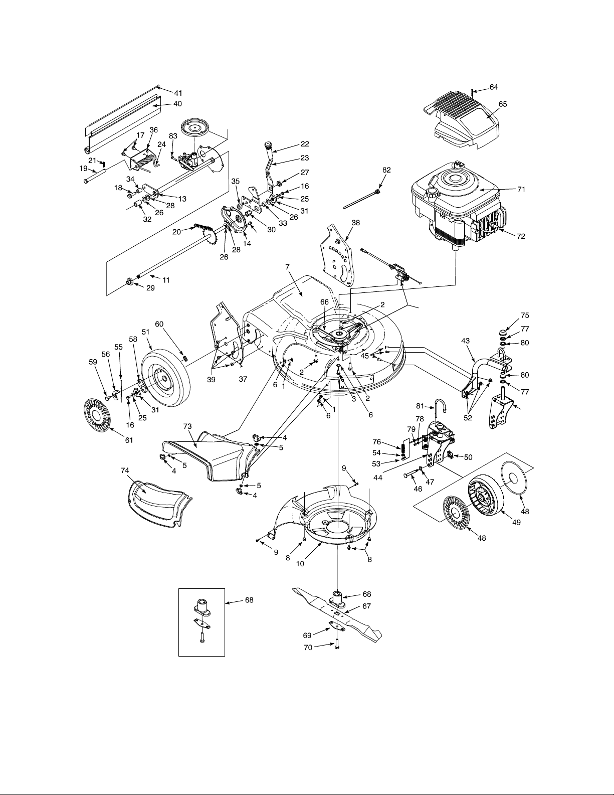
Models 960 thru E969
Transmission and pulley
for reference only
8
Pulley Assembly for
reference only
84
26
Page 27

Models 960 thru E969
Ref.
No.
1 710-0134 Scr. Carr . 1/4-20 x .62
2 710-0654A Scr. TT :3/8-18:1.00
3 710-0703 Scr. 1/4-20 x .750
4 712-0397 Wing Nut 1/4-20
5 723-0233 Nut, Push .25 I.D. x .50 O.D .
6 736-0204 Wash. Fl. .334 I.D .x . 62 x.03
7 782-0046A-
8 71 0-0653 Scr. TT. 1/4-20 x .375
9 710-0969 Scr. T russ Machi ne TT
10 731-1828 Baffle
11 638-0012 Rear Axle Ass’y
12 782-0566 Pivot Arm Ass’y
13 682-7526 T rans . Axle Ass’y
14 682-7528 Chain Cove r Ass’y
16 710-0751 Cap Screw HH 1/4-20 x .620
17 710-0896 Scr. AB 1/ 4-14 x .825
18 710-1315 Scr. 3/8 116 x .25
19 711-0835 Clevis Pin .50 Dia. x 4. 82
20 713-0453 Chain-Endls.
21 714-0474 Cotter Pin .125O .D . x .7 5
22 720-0223 Grip
23 732-0803A Spring Lev er
24 732-0832 T orsio n Spring
25 736-0270 Bell Wash . .285 x .75 x .082
26 736-0369 Fl. Wash..508 I.D.
27 738-0529 Nut Shld. .825 Dia. x .165
28 741-0324 Hx.Flg. Brg..506 I.D. x .590
29 741-0522 Hx.Flg. Brg. .506 I.D . x.715
30 741-0978 Hx. Slv . Brg..504 I .D . x .8 30
31 748-0318 Wheel Rachet
32 750-0151 Spa. .550 I.D . x / 750 O .D .
33 750-0515 Spa. .51 .D . x .70 O .D . x 38
34 750-0807 Spa. .385 x .624 x .700
35 750-1056 Shld. Spa. .385 I.D. X .715
36 782-0568 Brkt. - Ht. Adj. Spring
37 682-3052-
38 682-3053-
39 710-1348 Scr. AB 1/ 4-14 x .500
40 731-1901 T r ail Shield
41 732-0842 T r ail Shield W ire
42 682-9020A-
Part No. Description
Deck - 21”
0662
Handle Brkt. Assembly R.H.
0662
Handle Brkt. Assembly L.H.
0662
Caster Ass’y R.H (Not Shown)
0662
Ref.
No.
43 682-9021A-
44 682-9024A-
45 710-0260 Carr. Bolt 5/16-18 x . 62
46 711-1146 Caster Axle .374 Dia. x 2.50”
47 736-0232 Wave W ash.
48 731-1887 Hub Cap Whole Gra y
49 734-1857 Wheel 7 x 2, Caster Black
50 712-0397 Wing Nut 1/4-20 Thd.
51 734-1837 Wheel 9 x 2 Link Gra y,
52 712-3004A Lock Nut 5/1 6-18
53 714-0104 Pin, Cotter .072 x 1.12
54 736-0264 Fl. Wash. .330 x .830 x . 06
55 10622B Spring, Ratchet, Plastic
56 748-0381 Pawl - R.H.
57 748-0188B Pawl - L.H. (Not s hown)
58 16855 Ratchet Pa wl Pla te
59 738-0137A Shld. Scr. .34 0 x .285
60 712-0414 Top L ock W eld Nut 1/4-20
61 731-0981A Hubcap - Gra y
62 710-1237 Screw .620 Hx. Slt. Wsh.
63 751B213146 Casing Clamp , Throttle
64 710-1256 Scr. Hi-Lo #10 x 1.25
65 751B281451 Shroud - Gra y
66 754-0460 Belt
67 742-0741 21” Mulching Blade
68 753-0609 Blade Adapter Kit
69 736-0524A Blade Bell Support
70 710-1257 Hex Bolt 3/8-24x2.5”Lg.
71 — Engine
72 735-0639 Spark Plug Insulator
73 731-1832 Side Discharge Chute
74 731-1833 Mulch Cover
75 726-0214 Push Cap
76 732-0306 Compression Spring
77 736-0366 Fl. Wash. 5/8 O. D . x 1” O.D.
78 736-0931 Fl. Wash. .203 I.D . x .403
79 737-3000 Fitting - Lube
80 741-0685 Flange Bearing
81 747-0924 Lock Pin: Front Wh eel
82 725-0157 Cable Tie
83 710-0604 Hex Scr. 5/16-18
84 682-9026-
Part No. Description
Caster Ass’y L.H.
0662
Brkt. Ass’y , Wheel Caster RH
0662
Bracke t Assembl y, Wheel Caster LH
0662
27
Page 28
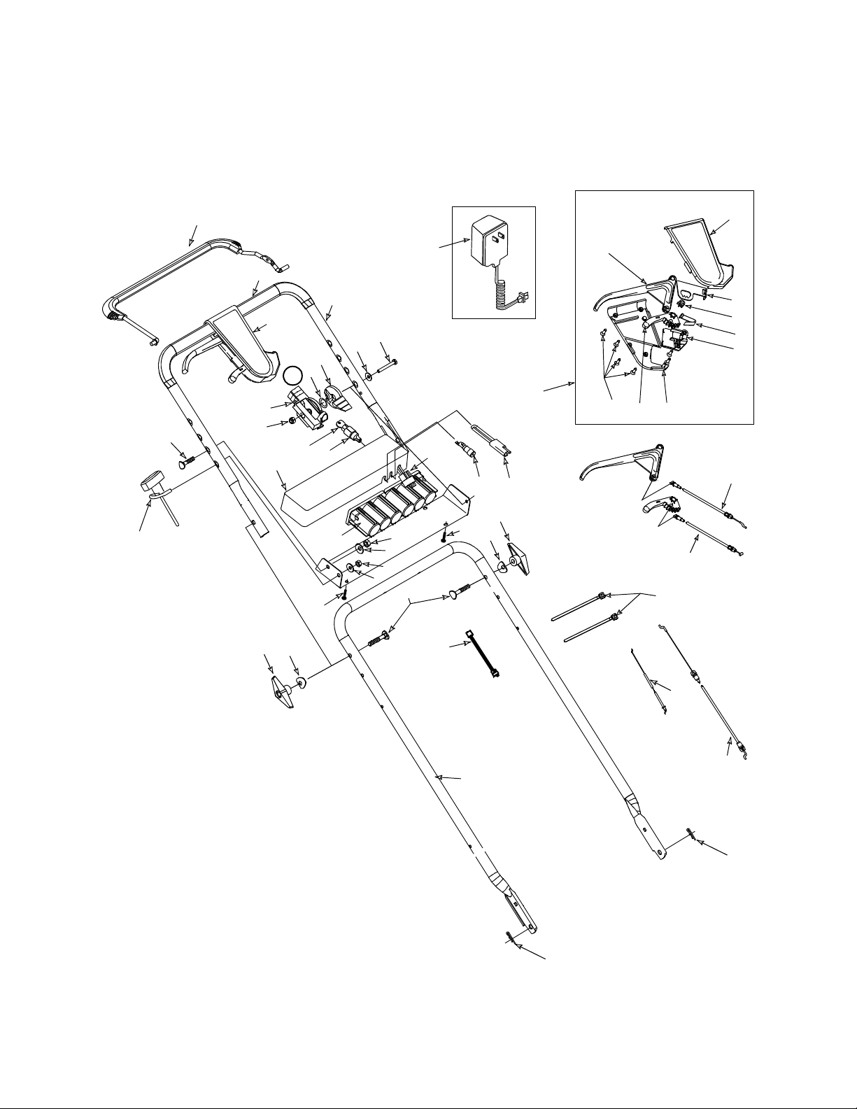
Model E969
27
28
A
13
10
55
29
46
47
9
24
16
21
18
20
23
A
12
37
7
11
40
42
51
41
39
47
50
54
38
45
43
44
3
51
5
1
19
17
22
26
25
4
3
5
52
15
14
30
2
2
28
Page 29

Model E969
Ref.
No.
1 710-1174 Bolt Cur. Car r. 5/16-18 x 2. 0
2 714-0104 Cotter Pin .072 x 1.12 Lg.
3 720-0241 Knob Assembly
4 726-0240 Strap 4.3 Lg.
5 736-0451 Wash. Sad. .320 ID x.830 OD
7 710-1205 Eyebolt
9 746-0876 Throttle Lever
10 736-0501 Spring W ash.C urved
11 712-0324 Nut 1/4-20 Top locknut Ins ert
12 646-0875 Housing, Th rottle
13 811-00303 Throttle Cont rol (Includes ref erence
14 746-0557 Control Cable 47” Lg.
15 746-0841 Cable Thro ttle 60” Lg.
16 731-0904 Upper Control Housi ng
17 731-0924 6 Speed Shi ft Lev er
18 713-0397 Gear Inse rt
19 710-0841 C Sunk Tap Screw #10 x .75 L
20 732-0627 Shift Le ver Spring
21 16864 6 Spd. Rack Cable Brkt.
22 731-0905 Low er Control Housing
23 731-0906 Cabl e Mounting Cap
24 731-0620 Control Lever
25 746-0939 6 Spd. Cable
Part No. Description
9,10,11 & 12)
Ref.
No.
26 746-0710A S.P. Cable
27 747-0824 Control Handle
28 720-0294 Foam Grip (2 Reqd. )
29 749-0439B Upper Handle
30 749-0907A Lower Handle
37 710-1250 Cur . Carr . Bol t 5/16-18 x 1” Lg.
38 712-0267 Hex Nut 5/16-18 T hd.
39 725-1276 Battery P ack - 12 Volt
40 731-0891A Battery T ray
41 725-0873 Ignition Switch
42 725-0201 Ignition K ey
43 425-1428
44 725-1206 Plug
45 725-1442 Wire Harness
46 710-0501 Hex Bo lt 1/4-20 x 2 ” Lg.
47 736-0270 Bell W ash 1 /4” I.D.
49 782-9012 Lowe r Battery Tray
50 736-0242 Bell W ash. 5/16 ” I.D .
51 710-0969 Truss Mch. T ap Scr . 1” Lg.
52 725-1538 Harness Ext.
54 712-0287 Hex Nut 1/4-20
55 725-0727 Battery Charger
Part No. Description
Fuse Holder
725-0298
Fuse 7-1/2 Amp
(Not shown)
Labels
Ref.
No.
N/I 77 7S30116 Danger - right rear
N/I 77 7S30118 Danger - discharge chute
N/I 77 7S30128 Warning - deck abo ve openi ng
N/I 777D02253 White LC 210 Lo go (959)
N/I 777-4724 White LC 215 Logo (96 9)
N/I 777-4725 White Logo
Part No. Description
(E969)
Ref.
No.
N/I 777D00299 W heel Cov er Label
N/I 777I20291 Height Adjustment La bel
N/I 777I20293 Drive le ver on Handle
N/I 777-5242 Caster Wheel Lock (969, E969)
N/I 777-5902 Electric Start Instructions
N/I 777-4857 White - On Battery P ack
Part No. Description
(E969)
(E969)
29
Page 30
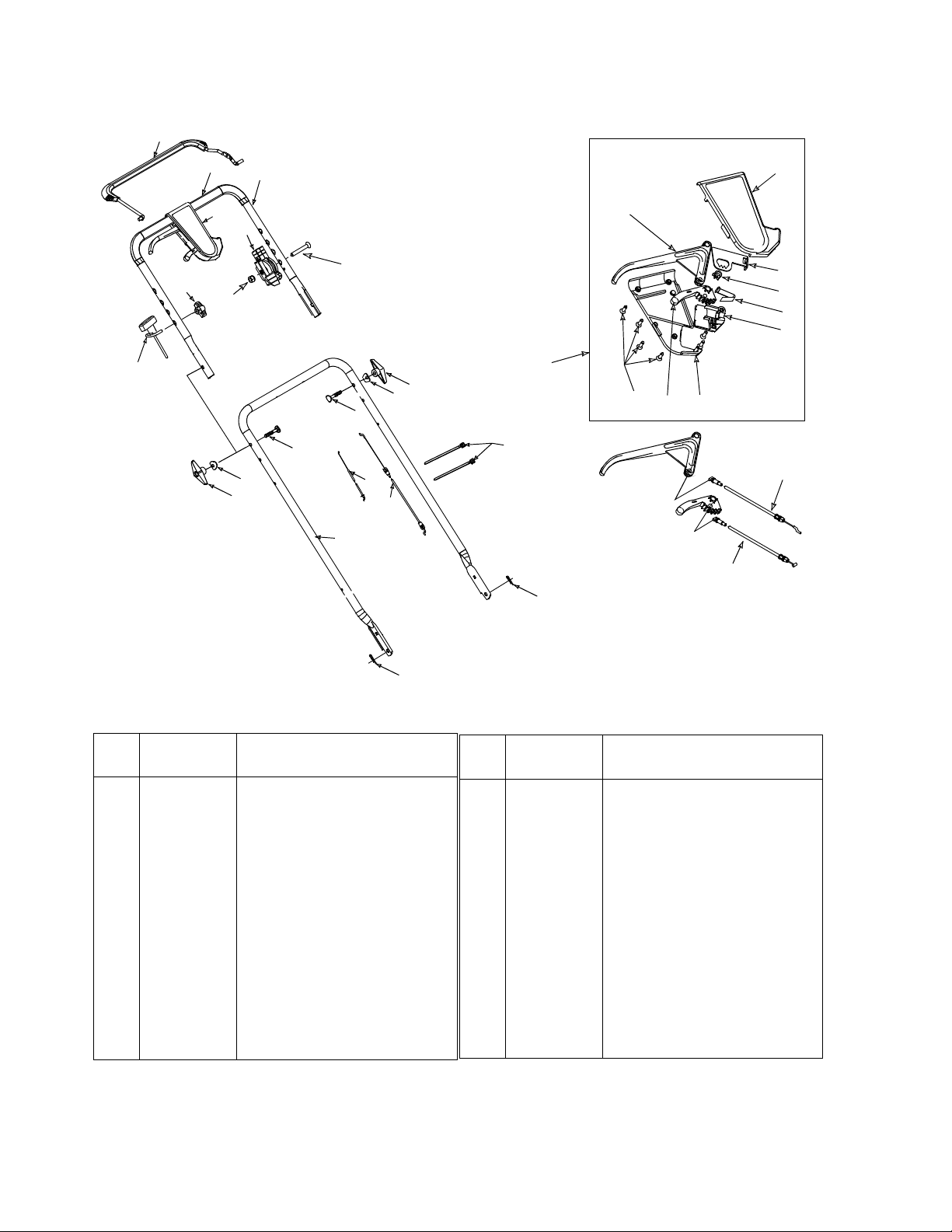
Models 950 thru 969
27
28
6
7
A
11
29
24
13
8
A
3
5
1
1
5
3
15
14
30
4
2
19
17
22
25
16
21
18
20
23
26
2
Ref.
No.
1 710-1174 Bolt Curv. Carr . 5/16-18 x 2.0
2 714-0104 Cotter Pin .072 x 1.12 Lg.
3 720-0241 Knob Assembly
4 726-0240 Strap
5 736-0451 Wash. Sad. .320 ID x.830 OD
6 720-0279 Knob Handle ERS - 1/4-20
7 710-1205 Rope Guide Eyebolt
8 710-1270 Oval C-Sunk Screw
11 7 12-0324 Nut 1/4-20 Top lock Nut Insert
13 746-0883 Control Housing
14 7 46-0912 Control Cabl e 44” Lg.
16 7 31-0904A Upper Control Housing
17 731-0924 6 Speed Shift Lever
18 713-0397 Gear Insert
Part No. Description
Ref.
No.
19 7 10-1667A CSunk Tap Scr #10 x .75 L
20 7 32-0627 Shift Lever Spring
21 1 6864 6 Spd. Rack Ca ble B rkt.
22 7 31-0905A Lower Contro l Housing
23 731-0906 Cable Mounting Cap
24 731-0620 Control Lever
25 7 46-0939 6 Spd. Cable
26 7 46-0713 S.P. Cable
27 647-0004 Control Handle
28 7 20-0294 Foam Grip (2 Reqd.)
29 7 49-0439C Upper Handle
30 7 49-0907A Lower Handl e
Part No. Description
30
Page 31
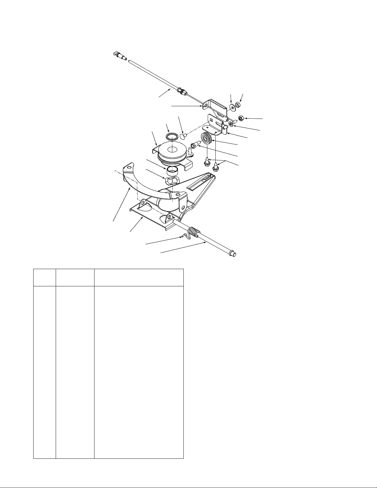
Models 950 thru E969
1
15
3
13
2
6
8
19
9
16
14
12
10
18
17
7
5
Ref.
No.
1 746-0939 6 Spd. Cable
2 656-0613 Pulley Ass’y Mu lt - Spd.
3 710-0167 Scr. 1 /4-20 x .50 Ca rr.
4 710-0896 Scr. AB 1/4-14 x .625 Hex hd.
5 711-1114 Pivot Shaft
6 712-0287 Nut 1/4-20
7 732-0807 T o rsion Spring LH
8 736-0270 Bell Wash. .265 X .75 X .062
9 736-0329 Lock W ash. 1/ 4 Reg Duty
10 736-0526 Wav e W ash. 1.38 x .88 x .029
11 738-0924 Shld.Scr. . 375 x 1/4 -1 4AB
12 750-1070 Slev Spcr ..88 I D 1.00 OD x.48
13 750-1071 Slev Spcr .88 ID x 1.13 ID x .12
14 756-0625 Roller Cable
15 782-7574-
16 782-7575-
17 782-7596 6 Sp. Control Arm
18 782-7597 6 Sp. Pivo t Brack et
19 712-0138 Hex Nut 1/4-28
Part No. Description
Wsh.
6 Spd. Cable Adj. Bracket
0662
6 Spd. Cable Mt. Bracket
0662
11
4
31
Page 32

MANUFACTURER’S LIMITED WARRANTY FOR:
The limite d warrant y set for th be low is gi ven by White Outdoor Products Co. with respect to new merchandise purchased and used in the United States, its possessions and
territories.
White Outdoor Products Co. warrants this product against
defects in material and workmanship for a period of two (2)
years commencing on the date of original purchase and
will, at its option, repair or replace, free of charge, any part
found to be defective in material or workmanship. This limited warranty shall only apply if this product has been operated and maintained in accordance with the Operator’s
Manual furnished with the product, and has not been subject to misuse, abuse, commercial use, neglect, accident,
improper maintenance, alteration, vandalism, theft, fire,
water or damage because of other peril or natural disaster.
Damage resulting from the installation or use of any acce ssory or attachment not approved by White Outdoor Products Co. for use with the product(s) covered by this manual
will void your warranty as to any resulting damages.
Normal wear parts or components thereof are subject to
separate terms as follows: All normal wear part or component failures will be covered on the product for a period of
90 days regardless of cause. After 90 days, but within the
two year period, normal wear part failures will be covered
ONLY IF caused by defects in material or workmanship of
OTHER component parts. Normal wear parts and components include, but are not limited to, belts, blades, blade
adapters, grass bags, rider deck wheels, seats, snow
thrower skid shoes, shave plates and tires. Batteries are
covered by a 90-day limited replacement warranty.
HOW T O OBTAIN SERVICE: W arr anty service is a v aila b le ,
WITH PROOF OF PURCHASE THROUGH YOUR LOCAL
WHITE OUTDOOR DEALER. To locate the dealer in your
area, please check for a listing in the Yellow Pages or contact the Customer Dealer Referral Line of White Outdoor
Co. by calling 1-330-225-8883 or writing to P.O. Box
361131, Clev e la nd, Ohio 44136-0019.
This limited warranty does not provide coverage in the
following cases:
a.The engine or component parts thereof. These items
carry a separate manufacturer’s warranty. Please refer
to the applicable manufacturer’s warranty on these
items.
b.Routine maintenance items such as lubricants, filters,
blade sharpening and tune-ups, or adjustments such
as brake adjustments, clutch adjustments or deck
adjustments; and normal deterioration of the exterior
finish due to use or exposure.
c. Log splitter pumps, valves and cylinders have a sepa-
rate one year warranty.
d. White Outdoor Co. does not extend any warranty for
products sold or exported outside of the United States
of America, its possessions and territories, except
those sold through White Outdoor Co. authorized
channels of export distribution.
No implied warranty, including any implied warranty of
merchantability or fitness for a particular purpose,
applies after the applicable period of express written
warranty above as to the par ts as ident ified. No o ther
express war ranty or guaranty, whether wri tten or or al,
except as mentioned above, given by any person or
entity, including a dealer or retailer, with respect to any
product shall bind White Outdoor Co. During the
period of the Warranty, the exclusive remedy is repair
or replacement of the product as set forth above.
(Some states do not allow limitations on how long an
implied warranty lasts, so the above limitation may not
apply to you.)
The provisions as set f orth in this W a rranty pr o vide the
sole and exclusive remedy arising from the sales.
White Outdoor Co. shall not be liable for incidental or
consequential loss or damages including, without limitation, expenses incurred for substitute or replacement lawn care services, for transportation or for
related expenses, or for rental expenses to temporarily
replace a warranted product. (Some sta tes do not allow
the exclusion or limitation of incidental or consequential
damages, so the above exclusion or limitation may not
apply to you.)
In no event shall recover y of any kind be greater than the
amount of the purchase price o f the pro duct sold . Alter ati on
of the safety features of the product shall void this Warranty. You assume the risk and liability for loss, damage, or
injury to you and your property and/or to others and their
property arising out of the use or misuse or inability to use
the product.
This limited warranty shall not extend to anyone other than
the original purchaser, original lessee or the person for
whom it was purchased as a gift.
How State Law Relates to this Warranty: This limited
warranty gives you specific legal rights, and you may also
have other rights which vary from state to stat e.
 Loading...