

Page 1
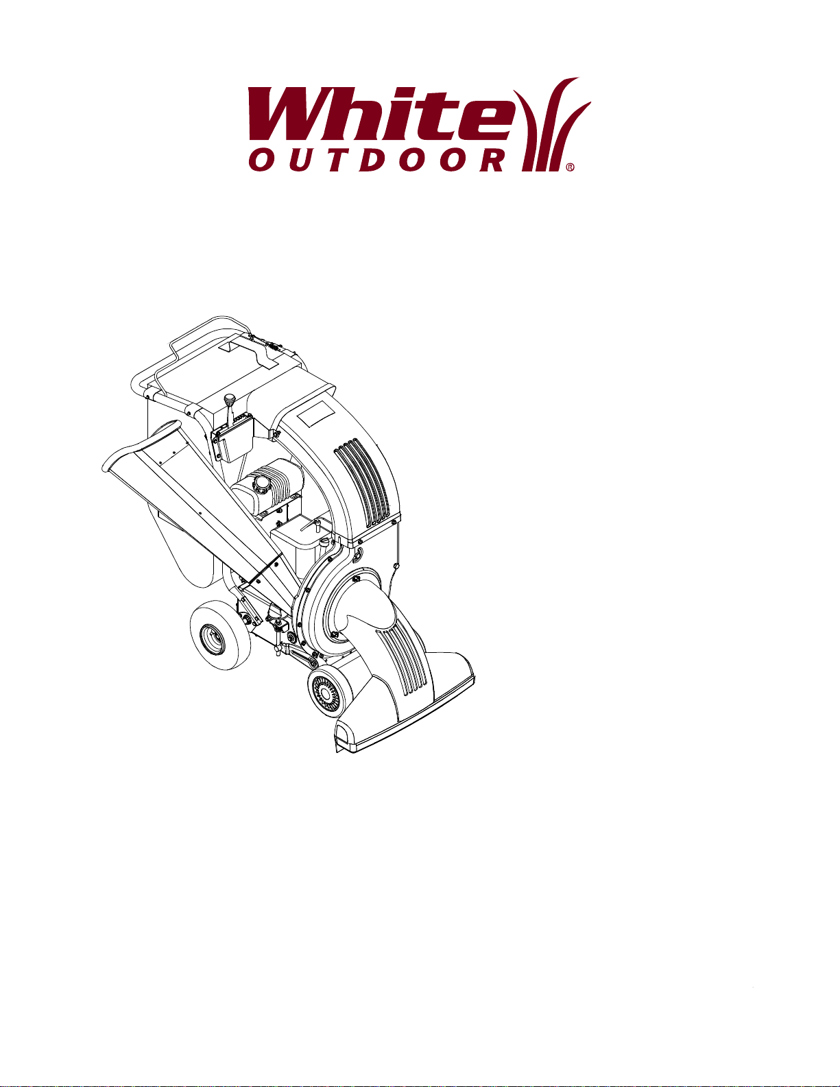
OPERATOR’S MANUAL
Chipper Shredder
Vacuum
Model Number
Yard Boss 950
IMPORTANT: READ SAFETY RULES AND INSTRUCTIONS CAREFULLY
Warning: This unit is equipped with an internal combustion engine and should not be used on or near any unimproved forest-
covered, brush-covered or grass-covered land unless the engine’s exhaust system is equipped with a spark arrester meeting
applicable local or state laws (if any). If a spark arrester is used, it should be maintained in effective working order by the operator.
In the State of California the above is required by law (Section 4442 of the California Public Resources Code). Other states may have
similar laws. Federal laws apply on federal lands. A spark arrester for the muffler is available through your nearest engine authorized
service dealer or contact the service department, P.O. Box 361131 Cleveland, Ohio 44136-9722.
WHITE OUTDOOR PRODUCTS COMPANY P.O. BOX 361131 CLEVELAND, OHIO 44136-9722
PRINTED IN U.S.A.
FORM NO.
770-10052C.fm
(8/01)
Page 2
TABLE OF CONTENTS
Content Page
Important Safe Operation Practices...................................................................3
Assembling Your Chipper Shredder Vacuum ....................................................5
Know Your Chipper Shredder Vacuum..............................................................7
Operating Your Chipper Shredder Vacuum .......................................................8
Adjusting Your Chipper Shredder Vacuum ........................................................10
Maintaining Your Chipper Shredder Vacuum.....................................................10
Troubleshooting.................................................................................................14
Parts List............................................................................................................16
FINDING MODEL NUMBER
This Operator’s Manual is an important part of your new chipper shredder vacuum. It will help you
assemble, prepare and maintain the unit for best performance. Please read and understand what it says.
Before you start assembling your new equipment, please locate the model plate on the
equipment and copy the information from it in the space provided below. The information on
the model plate is very important if you need help from our Customer Support Department or
an authorized dealer.
• You can locate the model number by standing behind the unit and looking down at the frame below
the engine. A sample model plate is explained below. For future reference, please copy the model
number and the serial number of the equipment in the space below.
(Model Number)
(Serial Number)
WHITE OUTDOOR
PRODUCTS COMPANY
P.O. B OX 361131
CLEVELAND, OHIO 44136
Copy the model number here:
Copy the serial number here:
CALLING CUSTOMER SUPPORT
If you have difficulty assembling this product or have any questions regarding the controls, operation or
maintenance of this unit, please call the Customer Dealer Referral Line.
Call 1- (800)-949-4483 to reach the Customer Dealer Referral Line. Please have your unit’s
model number and serial number ready when you call. See previous section to locate this
information.
For more details about your machine, visit our website at www.whiteoutdoor.com
2
Page 3

SECTION 1: IMPORTANT SAFE OPERATION PRACTICES
WARNING: This symbol points out important safety instructions which, if not followed, could
endanger the personal safety and/or property of yourself and others. Read and follow all instructions in
this manual before attempting to operate this machine. Failure to comply with these instructions may
result in personal injury. When you see this symbol - heed its warning.
WARNING: Th e Engine Exhaust from this pr oduct contains chemicals kno wn to the
State of Californi a to cause cancer, birt h defects or other re productive h arm.
DANGER: This machine was built to be operated according to the rules for safe operation in this
manual. As with any type of power equipment, carelessness or error on the part of the operator can
result in serious injury. This machine is capable of amputating hands and feet and throwing objects.
Failure to observe the following safety instructions could result in serious injury or death.
TRAINING
1. Read, understand, and follow all instructions on the
machine and in the manual(s) before attempting to
assemble and operate. Keep this manual in a safe
place for future and regular reference and for
ordering replacement parts.
2. Be familiar with all controls and their proper
operation. Know how to stop the machine and
disengage them quickly.
3. Never allow children under 16 years old to operate
this machine. Children 16 years old and over
should read and understand the operation
instructions and safety rules in this manual and
should be trained and supervised by a parent.
4. Never allow adults to operate this machine without
proper instruction.
5. Keep bystanders, helpers, pets, and children at
least 75 feet from the machine while it is in
operation. Stop machine if anyone enters the area.
6. Never run an engine indoors or in a poorly
ventilated area. Engine exhaust contains carbon
monoxide, an odorless and deadly gas.
7. Do not put hands and feet near rotating parts or in
the feeding chambers and discharge opening.
Contact with the rotating impeller can amputate
fingers, hands, and feet.
8. Never attempt to unclog either the feed intake or
discharge opening, remove or empty vacuum bag,
or inspect and repair the machine while the engine
is running. Shut the engine off and wait until all
moving parts have come to a complete stop.
Disconnect the spark plug wire and ground it
against the engine.
PREPARA TION
1. Thoroughly inspect the area where the equipment
is to be used. Remove all rocks, bottles, cans, or
other foreign objects which could be picked up or
thrown and cause personal injury or damage to the
machine.
2. Always wear safety glasses or safety goggles
during operation or while performing an adjustment
or repair, to protect eyes. Thrown objects which
ricochet can cause serious injury to the eyes.
3. Wear sturdy, rough-soled work shoes and closefitting slacks and shirts. Loose fitting clothes or
jewelry can be caught in movable parts. Never
operate this machine in bare feet or sandals. Wear
leather work gloves when feeding material in the
chipper chute.
4. Before starting, check all bolts and screws for
proper tightness to be sure the machine is in safe
working condition. Also, visually inspect machine
for any damage at frequent intervals.
5. Maintain or replace safety and instructions labels,
as necessary.
6. To avoid personal injury or property damage use
extreme care in handling gasoline. Gasoline is
extremely flammable and the vapors are explosive.
Serious personal injury can occur when gasoline is
spilled on yourself or your clothes which can ignite.
Wash your skin and change clothes immediately.
a. Use only an approved gasoline container.
b. Extinguish all cigarettes, cigars, pipes, and
other source s of i gnitio n.
c. Never fuel machine indoors.
d. Never remove gas cap or add while the
engine is hot or running.
e. Allow engine to cool at least two minutes
before refueling.
f. Never over fill fuel tank. Fill tank to no more
than 1/2 inch below bottom of filler neck to
provide space for fuel expansion.
g. Replace gasoline cap and tighten securely.
h. If gasoline is spilled, wipe it off the engine
and equipment. Move machine to another
area. Wait 5 minutes before starting the
engine.
i. Never store the machine or fuel container
inside where there is an open flame, spark,
or pilot light (e.g. furnace, water heater,
space heater, clothes dryer, etc.)
3
Page 4

j. To reduce a fire hazard, keep machine free
of grass, leaves, or other debris build-up.
Clean up oil or fuel spillage and remove any
fuel soaked debris.
k. Allow machine to cool at least 5 minutes
before storing.
OPERATION
1. Do not put hands and feet near rotating parts or in
the feeding chambers and discharge opening.
Contact with the rotating impeller can amputate
fingers, hands, and feet.
2. Before starting the machine, make sure the chipper
chute, feed intake, and cutting chamber are empty
and free of all debris.
3. Thoroughly inspect all material to be shredded and
remove any metal, rocks, bottles, cans, or other
foreign objects which could cause personal injury
or damage to the machine.
4. If the impeller s trik es a fo reig n obj ect or if yo ur
machine should start making an unusual noise or
vibration, immediately shut the engine off. Allow the
impeller to come to a complete stop. Disconnect
the spark plug wire, ground it against the engine
and perform the following steps:
a. Inspect for damage.
b. Repair or replace any damaged parts.
c. Check for any loose parts and tighten to
assure continued safe operation.
5. Do not allow an accumulation of processed
material to build up in the discharge area. This can
prevent proper discharge and result in kickback of
material through the feed opening.
6. Do not attempt to shred or chip material larger than
specified on the machine or in this manual.
Personal injury or machine damage could result.
7. Never attempt to unclog either the feed intake or
discharge opening while the engine is running.
Shut the engine off, wait until all moving parts have
stopped, disconnect the spark plug wire and
ground it against the engine before clearing debris.
8. Never operate without vacuum bag and discharge
chute properly attached to the machine. Never
empty or change vacuum bag while the engine is
running. Zippered end of vacuum bag must be kept
closed at all times during operation.
9. Never operate without either the inlet nozzle or
optional hose attachment properly attached to the
machine. Never attempt to attach or change either
attachment while the engine is running.
10. Keep all guards, deflectors and safety devices in
place and operating properly.
11. Keep your face and body back and to the side of
the chipper chute while feeding material into the
machine to avoi d acci dent al kick back i njur ies.
12. Never operate this machine without good visibility
or light. Always be sure of your footing and keep a
firm hold on the handles.
13. Do not operate this machine on a gravel surface.
14. Do not operate this machine while under the
influence of alcohol or drugs.
15. Muffler and engine become hot and can cause a
burn. Do not touch.
16. Never pick up or carry machine while the engine is
running.
MAINTENANCE AND STORAGE
1. Never tamper with safety devices. Check t heir
proper operation regularly.
2. Check bolts and screws for proper tightness at
frequent intervals to keep the machine in safe
working condition. Also, visually inspect machine
for any damage and repair, if needed.
3. Before cleaning, repairing, or inspecting, stop the
engine and make certain the impeller and all
moving parts have stopped. Disconnect the spark
plug wire and ground it against the engine to
prevent unintended starting.
4. Do not change the engine governor settings or
overspeed the engine. The governor controls the
maximum safe operating speed of the engine.
5. Maintain or replace safety and instruction labels, as
necessary.
6. Follow this manual for safe loading, unloading,
transporting, and storage of this machine.
7. Never store the machine or fuel container inside
where there is an open flame, spark or pilot light
such as a water heater, furnace, clothes dryer, etc.
8. Always refer to the operator’s manual for proper
instructions on off-season storage.
9. If the fuel tank has to be drained, do this outdoors.
10. Observe proper disposal laws and regulations for
gas, oil, etc. to protect the environment.
4
Page 5
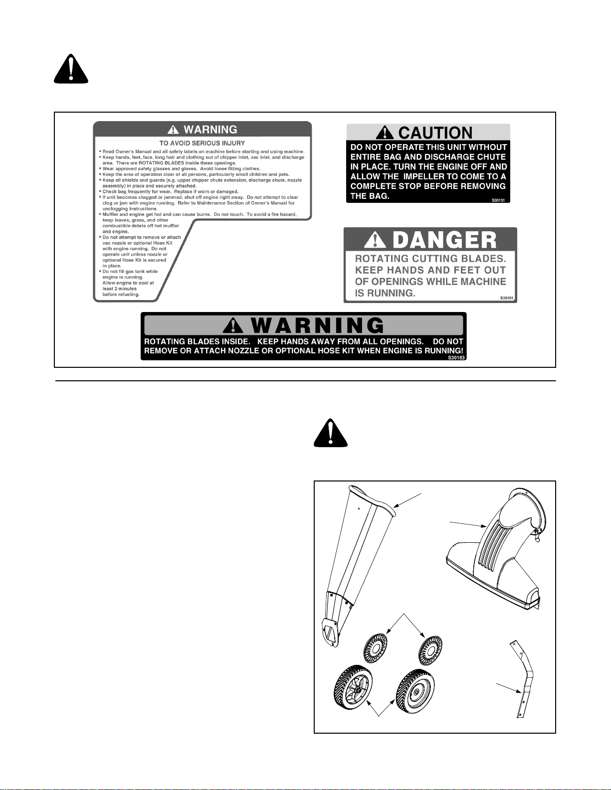
WARNING: - YOUR RESPONSIBILITY: Restrict the use of this power machine to persons who read,
understand and follow the warnings and instr uctions in this manual and on the machine.
NOTE: Not all safety labels shown may apply to your chipper shredder vacuum.
SECTION 2: ASSEMBLING YOUR CHIPPER SHREDDER VACUUM
IMPORT ANT :
in the engine. Be certain to service engine with gasoline
and oil as instructed in the separate engine manual
before operating your mower.
NOTE: Reference to right or left hand side of the
chipper shredder vacuum is observed from the
operating position.
Removing Unit From Carton
• Remove staples, break glue on top flaps, or cut
tape at carton end and peel along top flap to open
carton.
• Remove loose parts if included with unit (i.e.,
operator’s manual, etc.)
• Cut along corners, lay carton down flat, and remove
packing material.
• Roll or slide unit out of carton and check carton
thoroughly for loose parts.
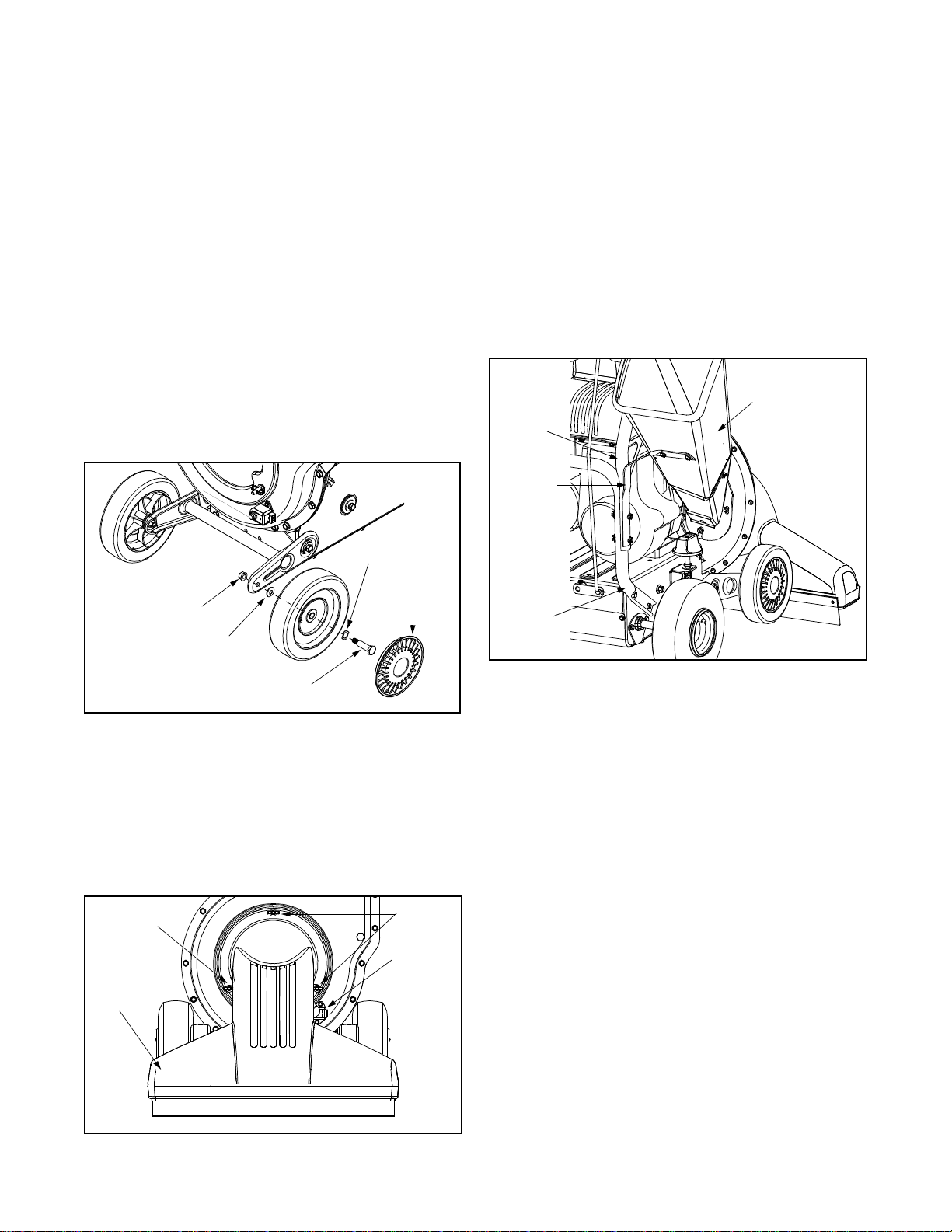
Loose Parts In Carton (See Figure 1)
• Front Wheels
• Hub Caps
• Nozzle
• Chipper Chute
• Support Bracket
• Bag and Safety Glasses (Not Shown)
This unit is shipped without gasoline or oil
WARNING: Before setting up your chipper
shredder vacuum, disconnect the spark
plug wire from the spark plug and ground
against the engine.
Chipper
Chute
Nozzle
Hub Caps
Support
Bracket
Front Wheels
Figure 1
5
Page 6
Attaching The Front Wheels
• Tilt the unit backward, so that it rests on the handle
(place a piece of cardboard under handle to avoid
scratches). Remove the packing material around
the wheel brackets.
• Remove the hex lock nuts and shoulder bolts from
the ends of the wheel bracket. See Figure 2.
• Place a wave washer on each shoulder bolt and
insert bolt through each wheel with the flat side of
wheel facing out.
• Place the cupped washer on shoulder bolt with the
crowned side against the wheel.
• Assemble each wheel to outside of wheel bracket
and secure with hex lock nut previously removed.
• Attach hub caps to wheels by placing hub cap
against the inner hub of wheel. Press firmly around
the center portion of hub cap in a circular motion.
The hub caps are flexible and it will snap over the
wheel hubs.
NOTE: The met al tab on the nozzle must de press the
safety switch button attached to the front of chipper
shredder vacuum or the engine will not start.
See Figure 3
• Set unit in the upright position.
Attaching The Chipper Chut e
• Remove the two hex bolts, flat washers, and hex
nuts that are attached to the support bracket.
• Attach the support bracket under the chipper chute
loosely using the hardware previously removed.
The hex bolts and washers should be inserted from
the inside of the chipper chute. See Figure 4.
Upper
Handle
Support
Bracket
Chipper Chute
Wave
Washer
Hub Cap
Hex Lock
Nut
Cupped
Washer
Shoulder
Bolt
Figure 2
Attaching The Nozzle
• Remove three wing nuts from the front of the
chipper shredder vacuum.
• Place nozzle in position over the three studs on unit
and secure with wing nuts just removed.
See Figure 3.
Wing
Nut
Nozzle
Wing
Nuts
Safety
Switch
Lower
Handle
Figure 4
• Remove the two he x lock nuts f rom t he he x bol ts
that secure the right side of the upper handle to the
lower handle. Leave the bolts and washers in
place. See Figure 4.
• Remove three cupped washers and hex nuts from
the weld studs besides the opening on the right
side of the chipper shredder vacuum.
• Place the chipper chute over the weld studs with
the slot at the bottom. Secure with cupped washers
(cupped side of washer goes against the chipper
chute) and hex nuts just removed and only tighten
the nuts slight ly for ease of further a ssembly.
• Place the support bracket through the two bolts in
the handle. Lifting up on the chipper chute will aid in
the alignment of the holes in the support bracket
with the bolts in the handle.
• Tighten all hardware securely on the chipper chute,
support bracket, and handle.
Figure 3
Attaching The Clutch Cable To Handle
• Loosen the hex nuts at the cable bracket and back
the bottom he x nut all the way down .
• While holding the drive clutch handle up, hook the
“Z” end of the cable into the drive clutch handle
from the outside. See Figure 5.
6
Page 7
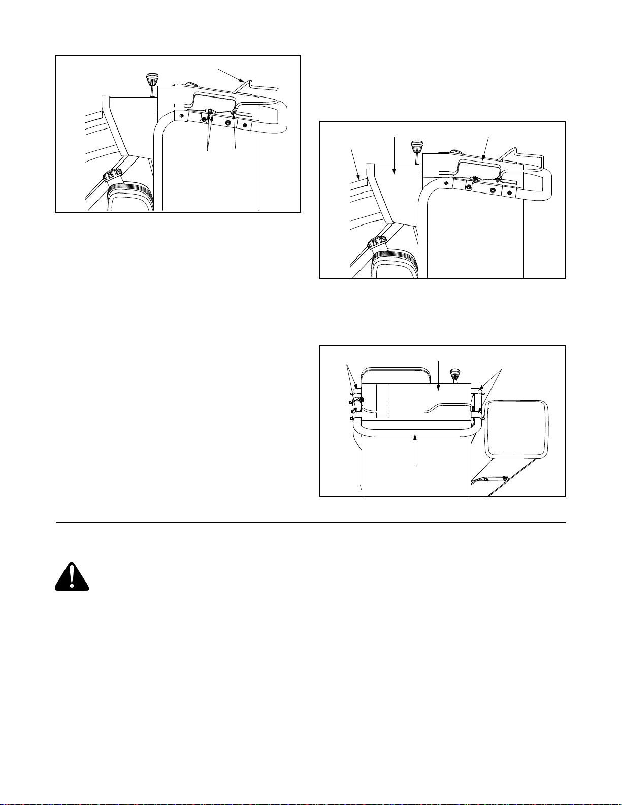
Drive Clutch
Handle
Hex
Z End
Nuts
Figure 5
Clutch Cable Adjustment
Adjust the hex nuts at the cable bracket so there is no
slack in the cable, but the cable should not be tight. Do
not overtighten the cable. See Figure 5.
To check the clutch adjustment, proceed as follows:
• Push the chipper shredder vacuum backward and
forward with the drive clutch handle released. It
should move freely.
• If it does not, loosen both hex nuts at the cable
bracket. Turn bottom nut clockwise to loosen the
cable. See Figure 5.
• Engage the drive clutch handle and try to push unit
backward and forward. The wheels should lock up.
• If the wheels do not lock up, loosen both hex nuts at
the cable bracket. Turn bottom nut counterclockwise to tighten the cable.
• Recheck adjustment and tighten both hex nuts
when correct adjustment is reached.
Attaching The Bag
• Place bag under of upper handle assembly and slip
the front opening on the bag over the discharge
chute, making certain it is over the rim on the
discharge chute. See Figure 6.
Discharge
Chute
• Place the four straps on the top of the bag over
upper handle, hooking them on the studs to secure
in place. Be sure the bag is under the drive clutch
handle. See Figure 7.
Bag Straps
Bag Opening
Figure 6
Bag
Upper Handle
Bag
Bag Straps
Figure 7
SECTION 3: KNOW YOUR CHIPPER SHREDDER VACUUM
WARNING: Be familiar with all controls
and their proper operation. Know how to
stop the machine and disengage them
quickly.
Bag
Collects shredded or chipped material fed through the
chipper chute or vacuumed up through the nozzle.
See Figure 8.
Chipper Chute
Allow twigs and small branches up to 3” in diameter to
be fed into the impeller for chipping. See Figure 8.
Nozzle Height Adjustment Knob
Used to adjust the nozzle ground clearance that will
provide the best performance for the operating
conditions. See Figure 8.
Nozzle
Yard waste such as leaves and pine needles can be
vacuumed up through the nozzle for shredding. See
Figure 8.
Drive Clutch Handle
The drive clutch handle is located above the upper
handle assembly. Squeezing the drive clutch handle
against the upper handle engages the wheel drive.
Release the drive clutch handle to stop the wheel drive.
See Figure 8.
7
Page 8
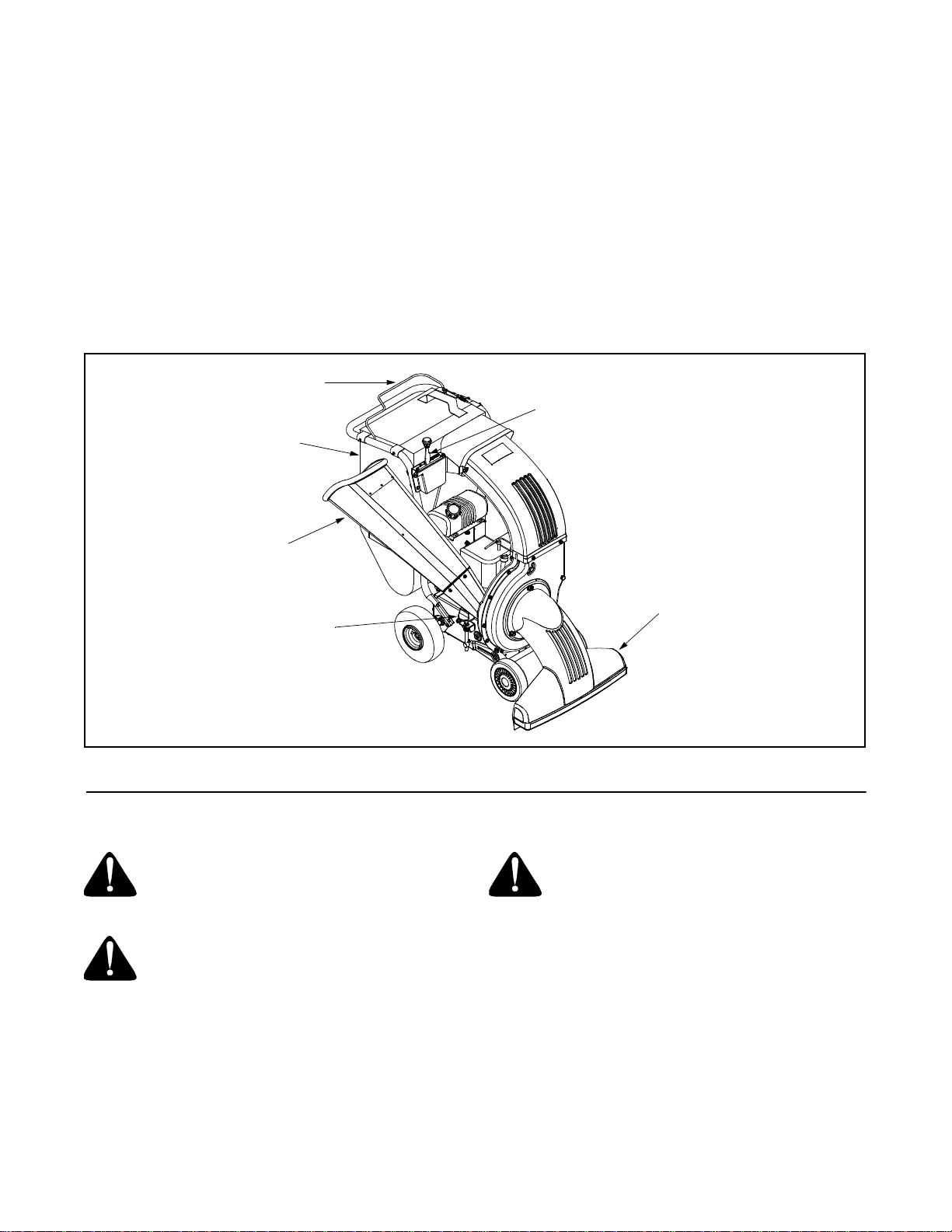
Shift Lever
The shift lever is located on the top right hand side of
unit. It is used to adjust the ground speed of the chipper
shredder vacuum when the drive clutch handle is
engaged. The shift lever can be place in one of eight
positions: six forward and two reverse positions.
See Figure 8.
Starter Handle (Not Shown)
The starter handle is located on the engine. Pull the
starter handle to start engine.
Engine Controls
See the separate engine manual for the location and
function of the controls on the engine.
Drive Clutch
Handle
Bag
Throttle Control Lever (Not Shown)
The throttle control lever is located on the engine. It
controls the engine’s speed and stops the engine. See
separate engine manual packed with unit for details.
Stopping Engine
• Move throttle control lever to STOP or OFF
position.
• Disconnect spark plug wire from spark plug and
ground against the engine.
Shift Lever
Chipper
Chute
Nozzle Height
Adjustment Knob
Figure 8
Nozzle
SECTION 4: OPERATING YOUR CHIPPER SHREDDER VACUUM
WARNING: Read, understand, and follow
all instructions and warnings on the
machine and in this manual before
operating.
WARNING: Always wear the safety
glasses provided with this machine during
operation or while performing any adjustments or repairs. Thrown objects which
ricochet can cause serious injury to the
eyes.
Gas And Oil Fill-Up
Service the engine with gasoline and oil as instructed in
the separate engine manual packed with your chipper
shredder vacuum. Read instructions carefully.
Starting Engine
• Attach spark plug wire to spark plug. Make certain
• Make certain drive clutch handle is in the
WARNING: Use extreme care when
handling gasoline. Gasoline is extremely
flammable and the vapors are explosive.
Never fuel machine indoors or while the
engine is hot or running. Extinguish
cigarettes, cigars, pipes, and other
sources of ignition.
the metal c ap on the end o f the spar k plug i s
fastened securely over the metal tip on the spark
plug.
disengaged (released) position.
8
Page 9
• Engines with choke lever:
Move choke lever on engine to CHOKE position. (A
warm engine may not require choking).
• Engines with primer:
Prime engine as instructed in separate engine
manual.
• The throttle control lever is located on the engine.
Move engine throttle control lever to FAST or
START position.
• Place one foot on the left rear wheel to prevent the
unit from skidding while starting.
• Grasp starter handle and pull rope out slowly until
engine reaches start of compression cycle (rope
will pull slightly harder at this point).
• Pull rope with a rapid, continuous, full arm stroke.
Keep a firm grip on starter handle. Let rope rewind
slowly.
• Repeat the previous steps until engine fires. When
engine starts, move choke control (if equipped)
gradually to RUN position.
WARNING: Keep bystanders, helpers,
pets, and children at least 75 feet fro m the
machine before starting and while
operating. Do not operate this machine
unless the discharge chute and bag have
been properly installed and secured to the
machine.
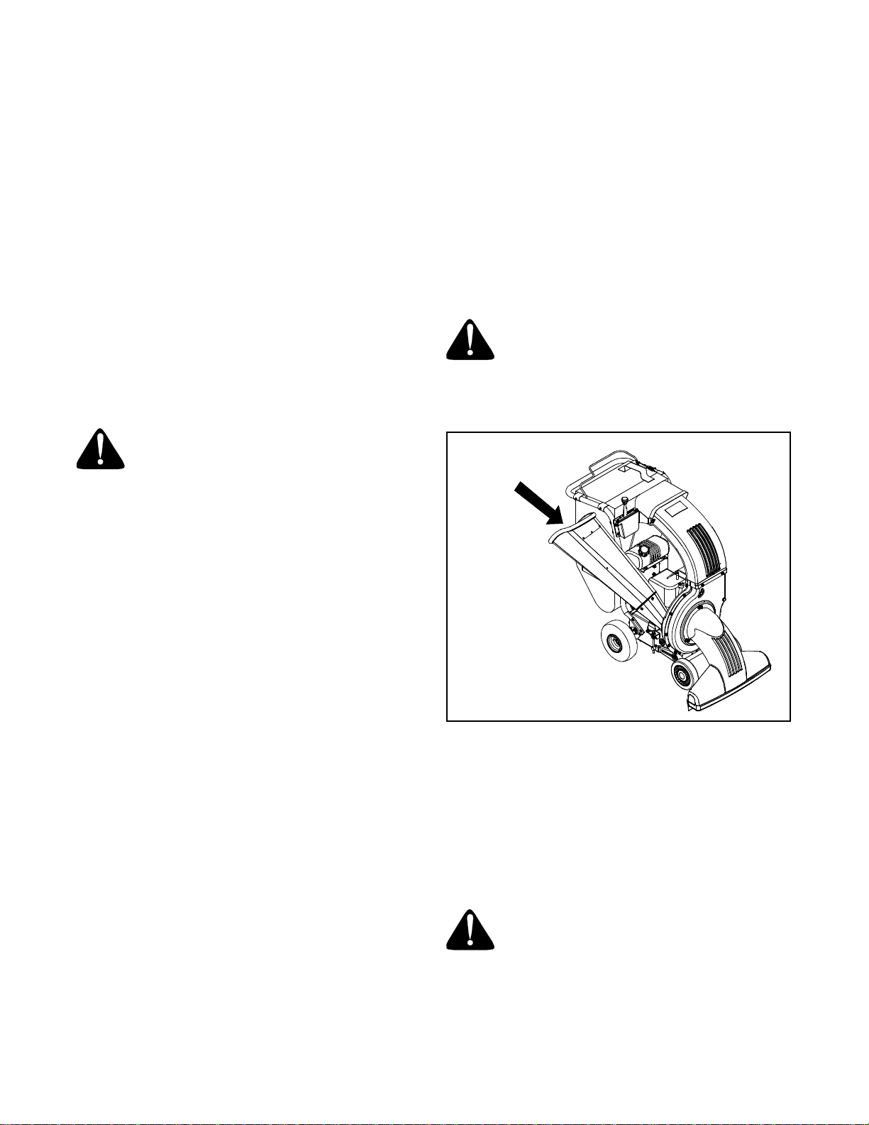
Using the Chipper Shre dder Vac uum
Place both hands on top of upper handle to push unit
over yard waste. Yard waste such as leaves and pine
needles can be vacuumed up through the nozzle for
shredding. After material has been shredded by the
blades on the impeller assembly, it will be discharged
into catcher bag. Do not attempt to shred or chip any
material other than vegetation found in a normal yard
(i.e. branches, leaves, twigs, etc.) Avoid fibrous plants
such as t omato vines until they are thor oughl y dri ed
out. Materials such as stalks or heavy branches up to 3”
in diameter may be fed into the chipper chute. See
Figure 9.
WARNING: Do not attempt to shred, chip,
or vacuum any material larger than
specified on the machine or in this
manual. Personal injury or damage to the
machine could result.
To Empty Bag
The bag is designed to be emptied without being
removed from unit. Open the large zipper in the rear of
the bag to empty the contents. If bag is removed for any
reason, follow the instructions for attaching the bag in
the ASSEMBLY section. Be certain the zipper is closed
completely when operating the unit.
To Engage Drive
IMPORT ANT :
before moving the shift lever.
With the engine running at top speed and drive clutch
handle disengaged, move shift lever into one of the six
FORWARD positions or two REVERSE positions.
Select a speed appropriate for the conditions that exist.
Use the slower speeds until you are familiar with the
operation of the chipper shredder vacuum.
To engage the wheel drive, hold the drive clutch handle
against the upper handle. Releasing the drive clutch
handle stops the wheels from driving. Release the drive
clutch handle to slow down when negotiating an
obstacle, making a turn, or stopping. Engage handle
slowly to prevent the front wheels from lifting up.
Always release the drive clutch handle
Figure 9
IMPORT ANT :
housing in the discharge area. If the flail screen
becomes clogged, remove and clean as instructed in
MAINTAINING YOUR CHIPPER SHREDDER
VACUUM. For best performance, it is also important to
keep the chipper blade sharp.
The flail screen is located inside the
Tire Pressure (Pneumatic Tires Only)
WARNING: Maximum tire pressure under
any circumstance is 30 psi. Equal tire
pressure should be maintained at all
times.
9
Page 10
SECTION 5: ADJUSTING YOUR CHIPPER SHREDDER VACUUM
WARNING: Do not at any time make any
adjustments without first stopping engine,
disconnecting spark plug wire, and
grounding it against the engine.
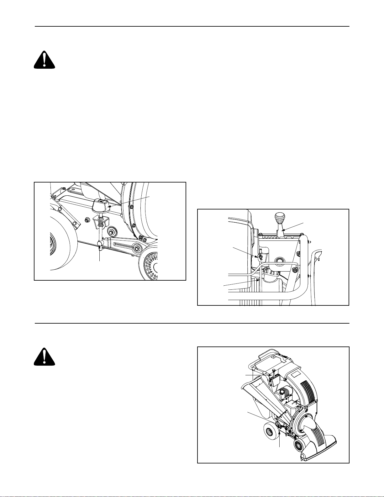
Height Adjustment
The height adjustment knob is located on the lower
right hand side of the chipper shredder vacuum. Turn
the knob clockwise to raise the nozzle and turn the
knob counterclockwise to lower the nozzle. The best
height for the nozzle will vary according to the
conditions. Adjust the height of the nozzle to find the
setting which gives the best performance for operating
conditions. In general, raise the nozzle to vacuum a
thick layer of leaves and lower the nozzle for smooth
surfaces. See Figure 10.
Height
Adjustment
Knob
Clutch Cable Adjustment
To adjust the clutch cable, refer to the Clutch Cable
Adjustment in the ASSEMBLY section.
Shift Rod Adjustment
If the shift rod needs adjustment proceed as follows:
• Remove the bag from the unit.
• Remove the hairpin clip and flat washer from the
upper end of the shift rod. Pull the ferrule out of the
hole in the shift lever, making certain the wave
washer remains in place on the ferrule.)
See Figure 11.
• Place the shift lever in 6th position (all the way to
the left).
• Push down on the shift rod and thread the ferrule
up or down the shift rod until the ferrule lines up with
the upper hole in the shift lever.
• Secure ferrule to the shift lever with flat washer and
hairpin clip.
Shift Leve r
Hairpin Clip &
Flat Washer
Ferrule
Figure 10
Shift
Rod
Figure 11
SECTION 6: MAINTAINING YOUR CHIPPER SHREDDER VACUUM
WARNING: Before performing any maintenance or repairs, stop the engine, wait
until the machine comes to a complete
stop, disconnect the spark plug wire and
ground against the engine to pr event unintended starting.
Lubrication
Wheels: Lubricate the rear wheels with light oil once a
season. See Figure 12.
Nozzle Height Pivot Bracket: Lubricate the pivot
points of the nozzle height pivot bracket once a season
with light oil. See Figure 12.
Shift Lever: Lubricate the pivot points on the shift lever
once a season with light oil. See Figure 12.
10
Lubricate
Lubricate
Lubricate
Figure 12
Page 11
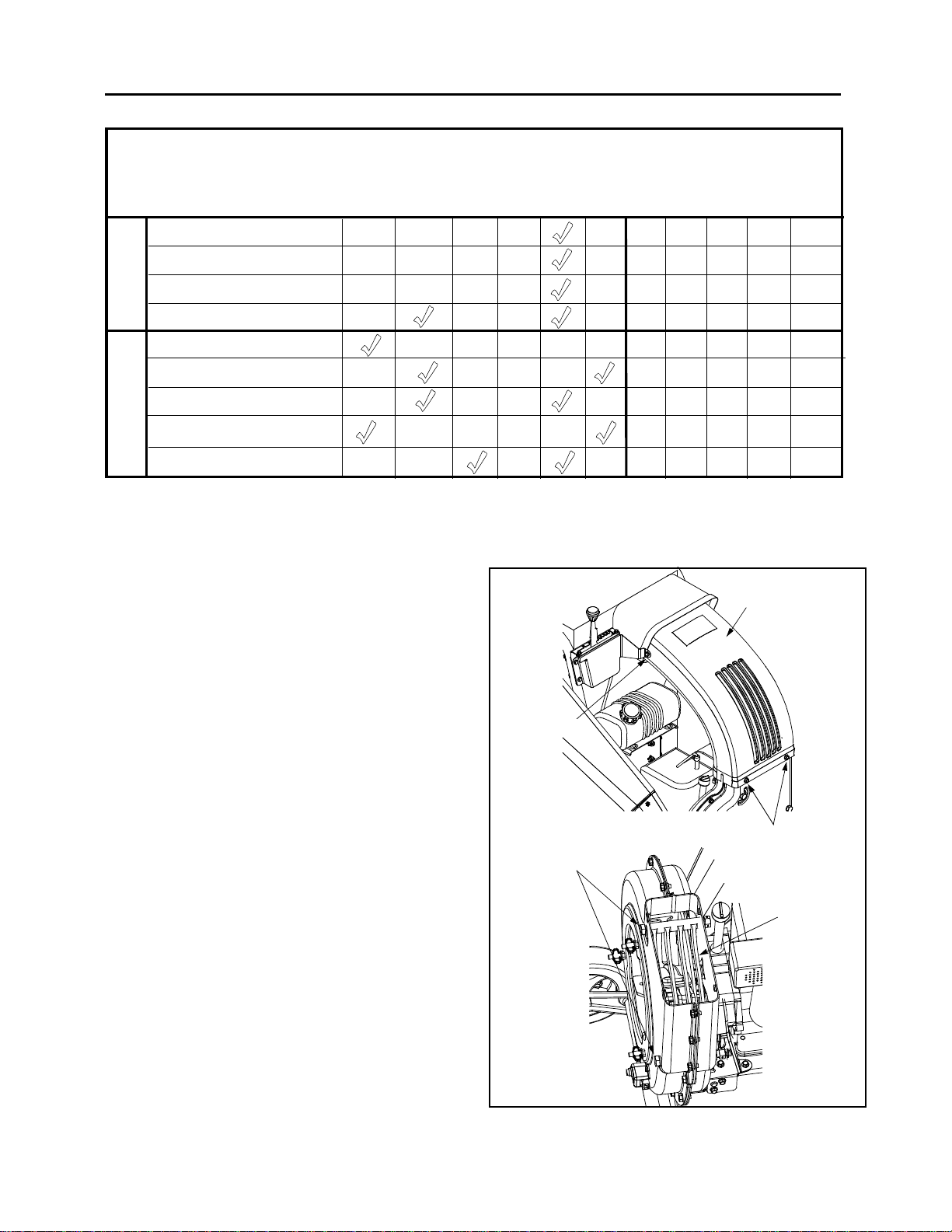
Customer Responsibilities
MAINTENANCE
SCHEDULE
Lubricate Wheels
T
C
Lubricate Shift Lever
U
D
O
Lubricate Pivot Bracket
R
P
Check Chipper Blades
Check Oil
Change Oil
E
Check Air Filter
N
I
G
N
Clean Engine
E
Check Spark Plug
e
s
u
h
c
a
e
e
r
o
f
e
B
E
s
r
u
o
h
5
2
y
r
e
v
u
o
h
0
5
y
r
e
v
v
E
E
s
s
r
r
u
o
h
0
0
1
y
r
e
O
n
e
o
g
s
a
r
a
o
e
t
s
s
a
e
r
e
o
f
c
e
n
B
SERVICE
DATES
Maintenance
Engine
Refer to the separate engine manual for all engine
maintenance instructions.
• Check engine oil level before each use as
instructed in the separate engine manual packed
with your unit. Read and follow instructions
carefully.
• Clean air cleaner every 25 hours under normal
conditions or once a season. Clean every few hours
under extr emely dusty co nditions. To service th e air
cleaner, refer to the separate engine manual
packed with your unit.
• The spar k plug should be cleaned and the gap
reset once a season. Check engine manual for
correct plug type and gap specifications.
Removing The Flail Scr een
If the discharge area becomes clogged, remove the flail
screen and clean area as follows:
• Stop the engine and make certain the chipper
shredder vacuum has come to a complete stop.
• Disconnect spark plug wire from spark plug and
ground against the engine.
• Remove the vacuum bag from the unit.
• Remove the four self-tapping screws from the
bottom of the discharge chute, and the hex bolt, flat
washer and hex nut from the top. Remove the
discharge chute assembly. See Figure 13.
• Remove the two hex bolts and hex nuts which
extend through the impeller housing. Lift the flail
screen from the inside the housing. See Figure 13.
• Clean the screen by scraping or washing with water
and reinstall the screen.
Discharge
Chute Assembly
Hex Bolt
Flat Washer
Hex Nut
Self-Tapping
Hex Bolts
Hex Nuts
Screws
Flail Screen
Figure 13
11
Page 12
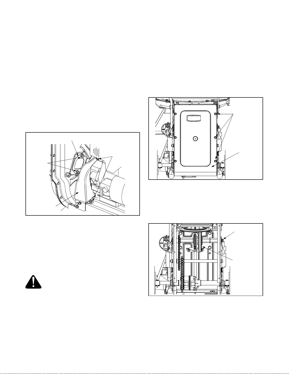
NOTE: Be certain to reassemble the flail screen with
the curved side down.
• Reattach the discharge chute assembly with the
hardware previously removed and connect the bag
to unit.
Sharpening Or Replacing Chipper Blad es
NOTE: When tipping the unit , empty the fuel tank and
keep spark plug side up.
• Disconnect the spark plug wire and ground it
against the engine.
• Remove the flail screen as instructed in the
previous section.
• Remove the plastic belt cover on the front of the
engine by removing the two self-tapping screws.
See Figure 14.
Access Plate
Changing The Friction Wheel Rubb er
The rubber on the friction wheel is subject to wear and it
should be checked or replaced after 50 hours of
operation. Replace friction wheel rubber if any signs of
wear or cracking are found.
• Drain the gasoline and oil from the chipper
shredder vacuum.
• Tip the unit backward so it rests on the handles.
• Remove the frame cover by removing eight self-
tapping screws from underneath the chipper
shredder vacuum. See Figure 15.
Self-Tapping
Screws
Self-Tapping
Hex
Lock Nuts
Belt
Cover
Screws
Figure 14
• Remove the access plate by removing two hex lock
nuts. See Figure 14.
• Locate one of the chipper blades in the access
opening by rotating the impeller assembly by hand.
Remove the chipper blade using a 3/16” allen
wrench and a 1/2” wrench.
• Remove other blade in the same manner to replace
or sharpen.
WARNING: Use caution when replacing
the blade, wear heavy gloves to avoid a
contact injury with the weld bolts or the
housing while loosening or tightening the
blade.
• When sharpening blade, follow the original angle of
grind. Also, make sure to remove an equal amount
from each blade and torque hardware 250 - 300 in.
lbs.
NOTE: Ma ke certain blades are r eassembled with the
sharp edge facing upward.
Frame
Cover
Figure 15
• Remove the hex shaft from the unit by removing the
hex bolts, lock washers, and flat washers from each
side of the frame. See Figure 16.
• Hold the friction wheel assembly and slide the hex
shaft out of the unit toward the right side.
Hex Bolt
Lock Washer
Flat Washer
Friction
Wheel
Figure 16
• Remove the six screws, three from each side, from
the friction wheel assembly and remove the friction
wheel rubber from between the friction wheel
plates.
• Attach the new friction wheel rubber to the friction
wheel assembly and tighten the six screws in
rotation and with equal force.
12
Page 13
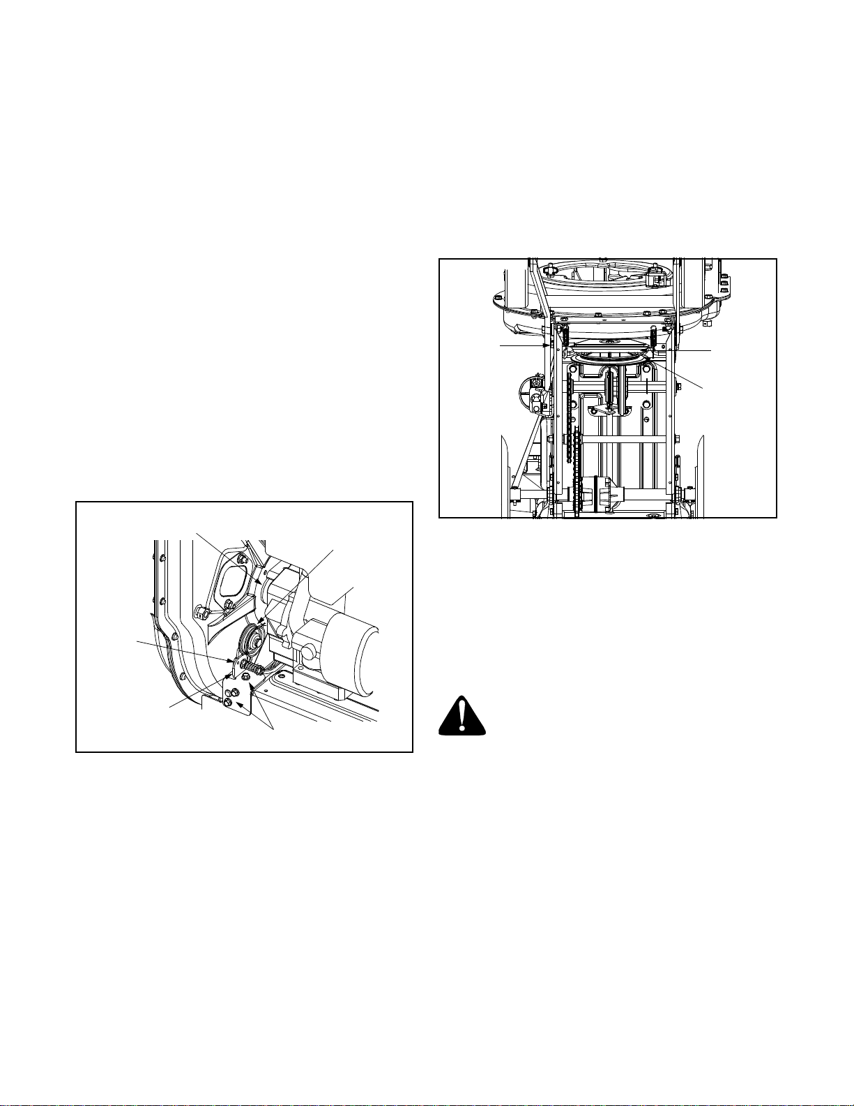
• Slide the friction wheel assembly up onto the shift
mechanism and then slide the hex shaft back into
the unit.
• Reassemble in reverse order and readjust the
clutch cable referring to the ASSEMBLY section.
• Loosen the nut on the stop bolt until there is
clearance between the support bracket and the
friction wheel disc. See Figure 18.
• Slip the belt between the friction wheel and the
friction wheel disc to remove and replace.
Belt Removal And Replacement
• Disconnect the spark plug wire and ground it away
from the spark plug.
• Drain the gasoline and oil from the chipper
shredder vacuum.
• Remove the plastic belt cover on the front of the
engine by removing two self-tapping screws. Refer
to Figure 14.
• Tip the unit backward so that it rests on the
handles.
• Remove the frame cover by removing eight selftapping screws from underneath the chipper
shredder vacuum. Refer to Figure 15.
• To remove the idler pulley bracket, first take the
tension off the belt by pivoting the idler and lining up
the holes in the idler bracket assembly. Then insert
a nail or similar object through the holes to hold the
idler pulley in the position. See Figure 17.
Engine
Pulley
Idler Pulley
Hole
NOTE: The suppo rt bracket must rest on the stop bolt
after the new belt has been assembled.
• Reassemble following the previous steps in reverse
order.
Hex Nut
Support
Bracket
Friction
Wheel Disc
Figure 18
Storing Y our Chipper Shredder V acuum
• Clean the equipment thoroughly.
• Wipe equipment with an oiled rag to prevent rust.
• Refer to engine manual for correct engine storage
instructions
• Store unit in a clean, dry area. Do not store next to
corrosive materials such as fertilizer.
Idler Bracket
Assembly
Self-Tapping Screws
Figure 17
• Remove the three self-tapping screws and lift off
the idler brac ket assembl y.
• Remove the hex bolt and lock washer from the
engine pulley and slip the engine pulley off the
engine shaft, removing the belt from the pulley.
WARNING: Never store the machine or
fuel container indoors where there is an
open flame, spark, or pilot light such as on
a water heater, furnac e, clothes dryer, or
other gas appliance.
13
Page 14

SECTION 7: TROUBLESHOOTING
Problem Cause Remedy
Engine fails to start 1. Spark plug wire disconnected.
2. Fuel tank empty or stale fuel.
3. Throttle control lever not in correct
starting position. (If Equipped)
4. Choke not in CHOKE posit ion.
(If Equipped)
5. Blocked fuel line.
6. Faulty spark plug.
Engine runs er ratic 1. Spark plug wire loos e.
2. Unit running on CHOKE.
(If Equipped)
3. Blocked fuel line or stale fuel.
4. Water or dirt in fuel system.
5. Dirty air cleaner.
6. Carburetor out of adjustment.
Too much vibration 1. Loose parts or damaged impeller. 1. See authorized service dealer.
Engine overheats 1. Engine oil level low.
2. Dirty air cleaner.
3. Carburetor not adjusted properly.
Occasional skip (hesitates)
at high speed
Unit does not discharge 1. Discharge chute clogged.
Rate of discharge slows
considerably or
composition of discharged
material changes.
NOTE: For repairs beyond the minor adjustments listed above, contact your nearest authorized service dealer.
1. Spark plug gap too close. 1. Adjust gap to .030”.
2. Foreign object lodged in impeller.
3. Low engine RPM
4. Vacuum bag is full.
1. Low engine RPM.
2. Chipper blade dull.
1. Connect wire to spark plug.
2. Fill tank with clean, fresh gasoline.
3. Move throttle lever to FAST position.
4. Move choke to CHOKE position.
5. Clean fuel line.
6. Clean, adjust gap, or replace.
1. Connect and tighten spark plug wire.
2. Move choke lever to OFF position.
3. Clean fuel line; fill tank with clean, fresh
gasoline
4. Drain fuel tank. Refill with fresh fuel.
5. Clean or replace air cleaner.
6. See authorized service dealer.
1. Fill crankcase with proper oil.
2. Clean or replace air cleaner.
3. See authorized service dealer.
1. Stop engine immediately and
disconnect spark plug wire. Clean flail
screen and inside of discharge opening.
2. Stop engine and disconnect spark plug
wire. Remove lodged object.
3. Always run engine at full throttle.
4. Empty bag.
1. Always run engine at full throttle.
2. Replace chipper blade or see your
authorized service dealer.
14
Page 15

NOTES
15
Page 16
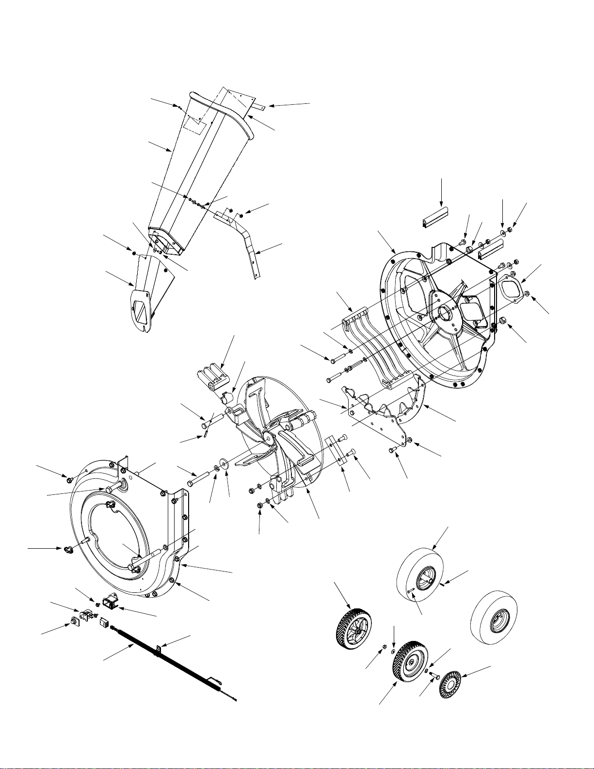
Model 950
3
4
5
6
6
7
9
5
27
28
2
7
1
11
14
15
12
10
8
18
19
20
13
16
17
13
38
36
42
37
41
40
44
36
39
31
30
29
43
32
12
33
35
34
19
21
26
48
25
49
24
50
22
17
23
45
46
47
51
53
16
48
52
Page 17

Model 950
Ref.
No.
1. 781-0633 Chute Flap Strip
2. 735-0249 Chute Flap
3. 72 8-0175 Pop Rivet
4. 731-1574 Chipper Chute
5. 710-0751 Hex Cap Screw 1/4-20 x .620
6. 73 6-01 73 Fl at Washer .28 ID x .74 OD
7. 712-3027 Hex Lock Nut 1/4-20
8. 781-0625 Support Bracket
9. 681-0068A Chipper Chute Assembly
10. 681-0059 In ner Hous in g Asse mbly
11. 723-0438 Rubber Seal
12. 710-0604 Hex Washer Screw 5/16-18 x .60
13. 712-0384 Hex Lock Nut 1/2-13
14. 736-0242 Bell Washer .345 ID x .88 OD
15. 712-3010 Hex Nut 5/16-18
16. 781-0627 Chipper Blade Cover
17. 712-3004A Hex Lock Nut 5/16-18
18. 719-0326 Flail Screen
19. 736-0119 Lo ck Washer 5/16
20. 710-0772 Hex Cap Screw 5/16-24 x 2.0
21. 781-0598 Lower Shredder Blade
22. 781-0599 Upper Shredder Blade
23. 710-3008 Hex Cap Screw 5/16-18 x .75
24. 710-1054 Hex Cap Screw 5/16-24 x 1.0
25. 781-0544 Chipper Blade
26. 681-0078 Impeller Assembly
27. 719-0329 Flail Blade
Part No. Part Description
Ref.
No.
28. 781- 073 5 Pin Clip
29. 711-0833B Clevis Pin
30. 715-0166 Pin
31. 710-1273 Hex Cap Screw 3/8-24 x 2.75
32. 736-0217 Lock Washer 3/8
33. 736-0247 Flat Washer 3/8 x 1.25
34. 712-0411 Hex Lock Nut 5/16-24
35. 681-0060 Outer Housing Assembly
36. 710-0607 Hex Washer Screw 5/16-18
37. 710-0382 Hex Cap Screw 1/2-13 x 5.0
38. 712-0421 Knob 5/16-18 x .70
39. 731-1613 Safety Switch Mounting Cover
40. 710-1268 Hex Washer Screw #10-16 x .30
41. 725-3166 Snap Mount Switch
42. 725-1700 Switch Cover
43. 726-0272 Clamp
44. 629-0241 Wire Harness
45. 634- 010 0 Wheel Assem b l y 10 x 4.0
46. 714-0104 Cotter Pin
47. 711-1017 Clevis Pin
48. 734-1513B Wheel Assembly 8 x 2.0
49. 712-0431 Hex Lock Nut 3/8-16
50. 736-0105 Bell Washer .401 ID x .870 OD
51. 736-0232 Wave Washer .53 ID x .78 OD
52. 738-0213 Shoulder Bolt
53. 731-0982A Hubcap
Part No. Part Description
NOTE: For painted parts, please refer to
the list of color codes below. Please add the
applicable color code, wherever needed, to
the part number to order a replacement part.
For instance , if a part, numbered 700 -xxxx,
is painted Oyster Gray, the part number to
order would be 700-xxxx-0662.
Oyster Gray: 0662
Powder Black: 0637
17
Page 18
Model 950
1
29
10
2
7
3
4
5
9
11
12
6
8
6
28
11
8
14
12
15
13
16
17
12
12
20
18
21
25
17
19
16
22
23
24
26
27
10
30
31
18
Page 19

Model 950
Ref.
No.
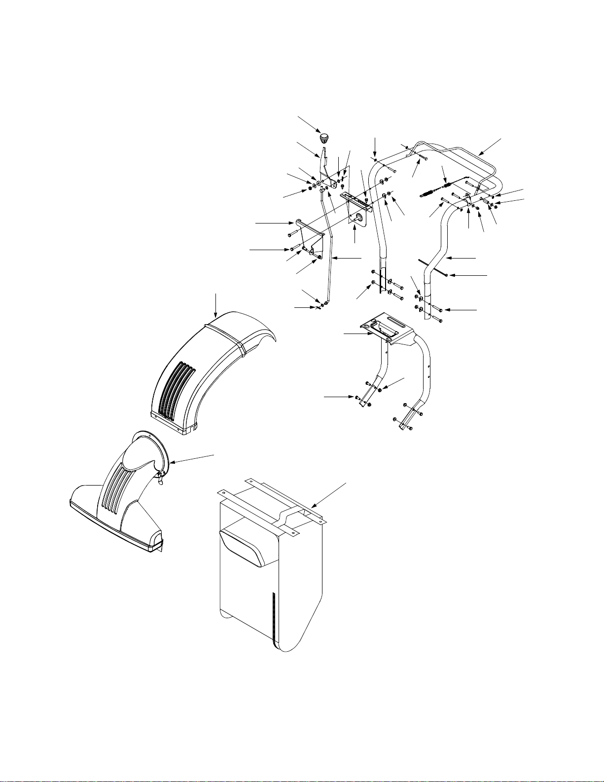
1. 720-0232 Shift Knob
2. 784-0297A Shift Lever
3. 73 5-0126 Rubber Washer
4. 736-0300 Flat Washer
5. 71 2-01 16 Lock Nut 3/8-24
6. 736-0413 Spring Washer
7. 736-0117 Flat Washer .375 ID x .620 OD
8. 714-0104 Cotter Pin
9. 781-0626 Shift Cover
10. 710-3103 Hex Cap Screw 5/16-18 x 2.0
11. 710-3008 Hex Cap Screw 5/16-18 x .75
12. 712-3004A Flange Lock Nut 5/16-18
13. 747-0626 Shift Rod
14. 681-0076 Shift Bracket Assembly
15. 710-0896 Hex Washer Screw 1/4-14 x .625
16. 1539-019 Push N ut .250
Part No. Part Description
Ref.
No.
17. 736-0451 Shoulder Washer .320 ID x .93 OD
18. 711-0737 Pin .250 x 1.75
19. 747-1133 Drive Clutch Handle
20. 746-1080 Clutch Cable
21. 710-0136 Hex Cap Screw 1/4-20 x 1.75
22. 736-0275 Flat Washer 5/16
23. 750-1185 Spacer .345 ID x .51 OD
24. 712-0442 Lock Nut 1/4-20
25. 781-0157 Cable Mounting Bracket
26. 749-1083 Upper Handle
27. 725-0157 Cable Tie
28. 649-0012 Lower Handle
29. 731-1573 Discharge Chute
30. 631-0028 Nozzle Assembly
31. 764-04 72 Vacuum Bag
Part No. Part Description
19
Page 20
Model 950
1
2
3
4
5
6
7
8
13
14
16
17
22
23
15
9
10
12
11
19
18
20
21
20
25
9
24
37
28
31
35
34
36
26
43
40
41
30
27
29
30
32
38
42
39
33
45
44
47
49
46
52
48
50
50
49
51
52
48
54
53
20
Page 21

Model 950
Ref.
No.
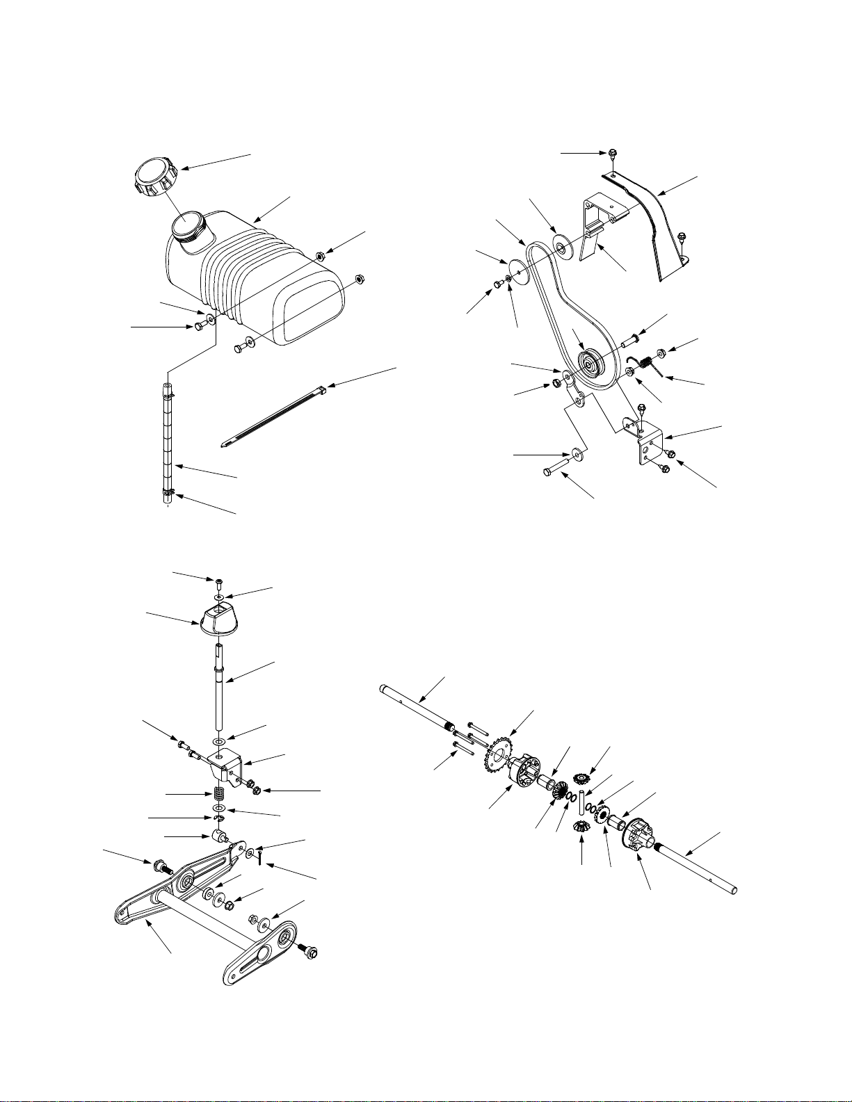
1. 75 1-06 03 Fuel C ap
2. 751-0610 Gas Tank - 1 Gallon
3. 71 2-3027 Hex Loc k Nut 1/4-20
4. 73 6-01 73 Flat Washer .28 ID x .74 OD
5. 710-0751 Hex Cap Screw 1/4-20 x .620
6. 726-0209 Cable Tie
7. 75 1-05 35 Fuel Lin e
8. 726-0205 Hose Clamp
9. 710-0896 Hex Washer Screw 1/4-14 x .625
10. 731-1584 Belt Cover
11. 719-0330A Engine Mounting Adapter
12. 756-0987 Pulley Half
13. 754-0256 V-Belt
14. 756-0986 Pulley Half
15. 736-0329 Lock Washer 1/4
16. 710-0230 Hex Cap Screw 1/4-28 x .50
17. 781-0614 Idler Bra cket
18. 756-0313 Flat Idler
19. 710-0723 Hex Cap Screw 3/8-16 x 1.25
20. 712-3004A Hex Lock Nut 5/16-18
21. 732-0745 Torsion Spring
22. 712-0266 Lock Nut 3/8-16
23. 748-0234 Shoul der Spac er
24. 710-0646 Hex Cap Screw 5/16-18 x 2.0
25. 781-0611 Idler Pivot Bracket
26. 710-0924 Machine Screw 1/4-20 x .75
27. 736-0270 Bell Washer .265 ID x .75 OD
Part No. Part Description
Ref.
No.
28. 720-0236 Knob
29. 747-03 61 Hei ght Adju stment Rod
30. 736-0369 Flat Washer .508 ID x 1.0 OD
31. 710-3008 Hex Cap Screw 5/16-18 x .75
32. 781-06 05 Hei ght Adju st ment Bracket
33. 712-3004A Hex Lock Nut 5/16-18
34. 732-0645 Compression Spring
35. 716-0104 E Ring
36. 711-1041 Adjustment Ferrule
37. 738-0955 Shoulder Screw 3/8-16
38. 736-0300 Flat Washer .406 ID x .875 OD
39. 714-0115 Cotter Pin
40. 711-0242 Spacer
41. 712-0431 Flange Lock Nut 3/8-16
42. 736-0247 Flat Washer .375 ID x 1.25 OD
43. 681-0096 Pivot Wheel Bracket Assembly
44. 711-1038 Axle Shaft .750 x 9.8
45. 710-1206 Hex Washer Screw 1/4-20 x 2.375
46. 713-04 45 Spro cket 22T
47. 719-0334 Differential Housing LH
48. 748-03 83 Flange Bearing .75 ID x 1.0 O D x 1 .5
49. 717-1358 Differential Gear 14T
50. 717-1437 Differential Gear 10T
51. 711-1035 Cross Shaft .427 x 2.7
52. 716-0232 Retaining Ring
53. 719-0333 Differential Housing RH
54. 711-1037 Axle Shaft .750 x 10.954
Part No. Part Description
IMPORTANT: For a proper
working machine, use Factory
Approved Parts.
V-BELTS are especially designed
to engage and disengage safely.
A substitute (non OEM) V-Belt can
be dangerous by not disengaging
completely.
21
Page 22
Model 950
3
2
1
14
16
15
44
17
13
27
29
7
12
35
8
36
34
30
37
26
36
4
3
39
35
38
40
38
41
42
43
6
4
12
18
19
5
3
21
11
10
9
20
8
33
31
28
5
32
24
22
23
26
25
22
Page 23

Model 950
Ref.
No.
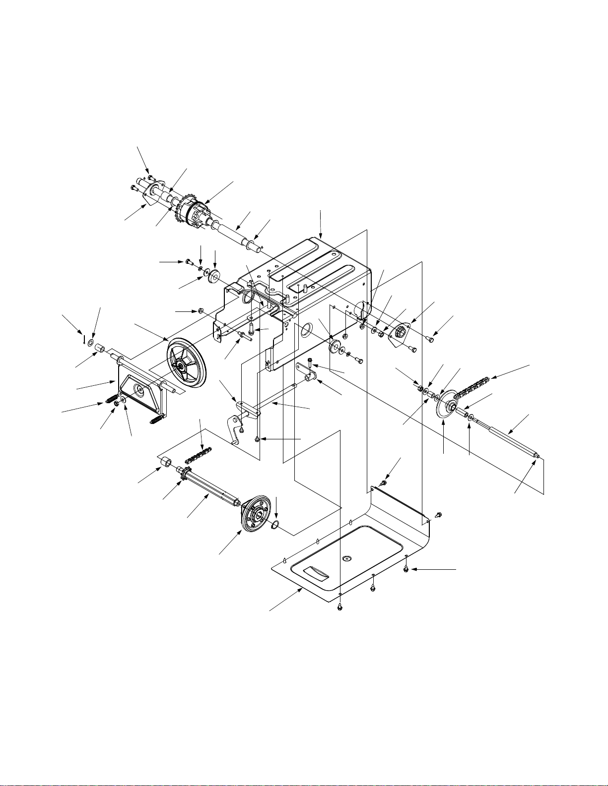
1. 618-0168 Transmission Assembly
2. 750-0981 Spacer .782 ID x 1.0 OD
3. 71 0-3008 Hex Ca p Screw 5/16 -18 x .75
4. 68 1-00 58 Axle Bra cket Assembly
5. 736-0287 Flat Washer .793 ID x 1.24 OD
6. 750-0980 Spacer .782 ID x 1.0 OD
7. 681-0081 Frame Assembly
8. 741-0563 Ball Bearing
9. 73 6-01 19 Lock Washer 5/16
10. 736-3089 Flat Washer .312 ID x .934 OD
11. 712-3004A Flange Lock Nut 5/16-18
12. 656-0012A Friction Disc Assembly
13. 736-0160 Flat Washer .53 ID x .93 OD
14. 714-0111 Cotter Pin
15. 748-0382 Spacer .508 ID x .75 OD
16. 732-0209 Extension Spring .48 OD x 2.03
17. 712-0711 Jam Nut 3/8-24
18. 736-0105 Spring Washer .401 ID x .870 OD
19. 750-0998 Spacer .675 ID x 1.0 OD
20. 713-0284 Chain #41 36 Links
21. 713-0413 Sprocket 10T #41
22. 711-1073 Hex Shaft .875
Part No. Part Description
Ref.
No.
23. 684-0042B Friction Wheel Assembly
24. 716-0102 Snap Ring 1.0 Dia.
25. 781-0612A Bottom Frame Cover
26. 710-0896 Hex Washer Screw 1/4-14 x .625
27. 710-0653 Hex Washer Screw 1/4-20 x .375
28. 784-5590 Frame Shift Bracket
29. 681-0082 Shift Shaft Assembly
30. 681-0072 Shift Assembly
31. 738-0908 Idler Bolt 5/16-18 x 2.25
32. 710-0502A Hex Washer Screw 3/8-16 x 1.25
33. 781-0638A Frame Reinforcement Plate
34. 710-0788 Hex Washer Screw 1/4-20 x 1.0
35. 736-0105 Spring Washer .401 ID x .870 OD
36. 712-0241 Hex Nut 3/8-24
37. 750-0979 Spacer .407 ID x .625 OD
38. 736-0267 Flat Washer .375 ID x .870 OD
39. 713-03 30 Spro cket Assembly 9T & 22T
40. 750-0351 Sleeve .380 ID x .623 OD x 1.5
41. 713-0374 Chain #420 36L
42. 750-0978 Spacer .407 ID x .625 OD x 7.86
43. 711-1028 Jack Shaft .375 x 11.40
44. 681-0055 Friction Wheel Support Bracket
Part No. Part Description
23
Page 24

MANUFACTURER’S LIMITED WARRANTY FOR:
The limite d warrant y set for th be low is gi ven by White Outdoor Products Co. with respect to new merchandise purchased and used in the United States, its possessions and
territories.
White Outdoor Products Co. warrants this product against
defects in material and workmanship for a period of two (2)
years commencing on the date of original purchase and
will, at its option, repair or replace, free of charge, any part
found to be defective in material or workmanship. This limited warranty shall only apply if this product has been operated and maintained in accordance with the Operator’s
Manual furnished with the product, and has not been subject to misuse, abuse, commercial use, neglect, accident,
improper maintenance, alteration, vandalism, theft, fire,
water or damage because of other peril or natural disaster.
Damage resulting from the installation or use of any accessory or attachment not approved by White Outdoor Products Co. for use with the product(s) covered by this manual
will void your warranty as to any resulting damages.
Normal wear parts or components thereof are subject to
separate terms as follows: All normal wear part or component failures will be covered on the product for a period of
90 days regardless of cause. After 90 days, but within the
two year period, normal wear part failures will be covered
ONLY IF caused by defects in material or workmanship of
OTHER component parts. Normal wear parts and components include, but are not limited to, belts, blades, blade
adapters, grass bags, rider deck wheels, seats, snow
thrower skid shoes, shave plates and tires. Batteries are
covered by a 90-day limited replacement warranty.
HOW T O OBTAIN SERVICE: W arr anty service is a v aila b le ,
WITH PROOF OF PURCHASE THROUGH YOUR LOCAL
WHITE OUTDOOR DEALER. To locate the dealer in your
area, please check for a listing in the Yellow Pages or contact the Customer Dealer Referral Line of White Outdoor
Co. by calling 1-330-225-8883 or writing to P.O. Box
361131, Clev e la nd, Ohio 44136-0019.
This limited warranty does not provide coverage in the
following cases:
a.The engine or component parts thereof. These items
carry a separate manufacturer’s warranty. Please refer
to the applicable manufacturer’s warranty on these
items.
b.Routine maintenance items such as lubricants, filters,
blade sharpening and tune-ups, or adjustments such
as brake adjustments, clutch adjustments or deck
adjustments; and normal deterioration of the exterior
finish due to use or exposure.
c. Log splitter pumps, valves and cylinders have a sepa-
rate one year warranty.
d. White Outdoor Co. does not extend any warranty for
products sold or exported outside of the United States
of America, its possessions and territories, except
those sold through White Outdoor Co. authorized
channels of export distribution.
No implied warranty, including any implied warranty of
merchantability or fitness for a particular purpose,
applies after the applicable period of express written
warranty above as to the par ts as ident ified. No o ther
express war ranty or guaranty, whether wri tten or or al,
except as mentioned above, given by any person or
entity, including a dealer or retailer, with respect to any
product shall bind White Outdoor Co. During the
period of the Warranty, the exclusive remedy is repair
or replacement of the product as set forth above.
(Some states do not allow limitations on how long an
implied warranty lasts, so the above limitation may not
apply to you.)
The provisions as set f orth in this W a rranty pr o vide the
sole and exclusive remedy arising from the sales.
White Outdoor Co. shall not be liable for incidental or
consequential loss or damages including, without limitation, expenses incurred for substitute or replacement lawn care services, for transportation or for
related expenses, or for rental expenses to temporarily
replace a warranted product. (Some sta tes do not allow
the exclusion or limitation of incidental or consequential
damages, so the above exclusion or limitation may not
apply to you.)
In no event shall recover y of any kind be greater than the
amount of the purchase price o f the pro duct sold . Alter ati on
of the safety features of the product shall void this Warranty. You assume the risk and liability for loss, damage, or
injury to you and your property and/or to others and their
property arising out of the use or misuse or inability to use
the product.
This limited warranty shall not extend to anyone other than
the original purchaser, original lessee or the person for
whom it was purchased as a gift.
How State Law Relates to this Warranty: This limited
warranty gives you specific legal rights, and you may also
have other rights which vary from state to state.
 Loading...