

White Outdoor ZT Zero 17, 17AA5A4G790, 1E154G20133, ZT Zero 22 Service Manual

For Discount White Outdoor Parts Call 606-678-9623 or 606-561-4983
Service Manual
ZT Zero Turn Rider
NOTE: These materials are for use by trained technicians who are experienced in the service and repair of outd oor power
equipment of the kind described in this publication, and are not intended for use by untrained or inexperienced individuals.
These materials are intended to provide supplemental information to assist the trained technician. Untrained or inexperienced individuals should seek the assistance of an experienced and trained professional. Read, understand, and follow all
instructions and use common sense when working on power equipment. This includes the contents of the product’s Operators Manual, supplied with the equipment. No liability can be accepted for any inaccuracies or omission in this publication,
although care has been taken to make it as complete and accura te as possible at the time of publication. However, du e to
the variety of outdoor power equipment and continuing product changes that occur over time, updates will be made to these
instructions from time to time. Therefore, it may be necessary to obtain the latest materials before servicing or repairing a
product. The company reserves the right to make changes at any time to this publication without prior notice and without
incurring an obligation to make such changes to previously published versions. Instructions, photographs and illustrations
used in this publication are for reference use only and may not depict actual model and component parts.
MTD Products Inc. - Product Training and Education Department
© Copyright 2005 MTD Products Inc. All Rights Reserved
www.mymowerparts.com
FORM NUMBER - 769-01421
12/2004

For Discount White Outdoor Parts Call 606-678-9623 or 606-561-4983
TABLE OF CONTENTS
General Information .............................................................................................................. 1
deck leveling .........................................................................................................................1
PTO/Deck Belt Replacement ............................................................................................... 2
Deck Removal ...................................................................................................................... 2
Blade Drive Belt Removal .................................................................................................... 2
Idler Arm Removal ................................................................................................................ 2
Blade Spindle Removal ........................................................................................................ 3
Drive Belt Replacement ........................................................................................................ 3
Servicing Electric PTO Clutch .............................................................................................. 3
Transmission Replacement .................................................................................................. 4
Steering Linkage: Adjustment .............................................................................................. 6
Pivot Bar ............................................................................................................................... 9
Seat Removal ..................................................................................................................... 10
Console Removal ............................................................................................................... 11
Battery Removal ................................................................................................................. 13
Fuel Tank Removal ............................................................................................................ 14
Control Shaft Replacement ................................................................................................ 15
Deck Lift Shaft Replacement .............................................................................................. 16
Electrical System Components .......................................................................................... 19
Relays ................................................................................................................................ 21
www.mymowerparts.com
For Discount White Outdoor Parts Call 606-678-9623 or 606-561-4983
White Outdoor ZT 17
17AA5A4G790
1E154G20133
GENERAL INFORMATION
2004 is the first year for the ZT. There are two models
ZT17 and ZT22. New for the ‘05 model year is a Kohler
Command 19 HP model with a 50” cutting deck.
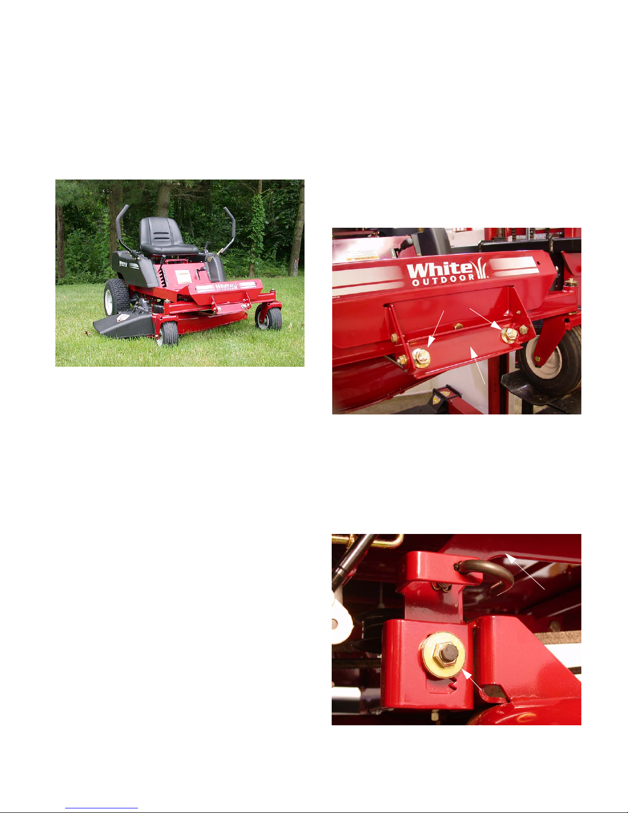
1. DECK LEVELING
1.1. To adjust the deck pitch, front to back, loosen or
tighten the jam nuts located on the front stabilizer bracket using a 15/16” socket and a 15/16”
wrench. The correct deck pitch should be 1/8” to
1/4” lower in the front than in the back, as measured from the blade tips. See Figure 1.1.
Jam Nuts
Front deck stabilizer bracket
Figure 1.1
This series of riders has the unique feature of not having to reset the PTO switch if the end us er tries to mow
in reverse. Once one lapbar is moved in to neutral or
forward the PTO will turn back on.
The “ZT 17” has a 17 HP Briggs & Stratton Intek which
is a single cylinder engine with full pressure lubrication.
The engine drives the dual Hydro-gear Hydrostatic
transmissions and the electric PTO. The PTO runs the
3-in-1blades on the 42” twin blade stamped deck. On
the front of the stamped frame is a large pivoting front
axle.
The “ZT 22” is very similar to the ZT 17 except for the
twin cylinder, 22 HP Briggs & Stratton Intek. Th ere are
also 4 wheels, instead of 2, on the 50” triple blade
stamped deck.
1.2. To level the deck, side to side, loosen the screw
on the left side adjustment gear using a 1/2”
socket. Using a 3/4” wrench, run the gear up or
down as necessary until each outside blade tip
is the same distance from the ground.
See Figure 1.2.
Deck hanger rod
Deck adjustment gear
Figure 1.2
www.mymowerparts.com
1
For Discount White Outdoor Parts Call 606-678-9623 or 606-561-4983
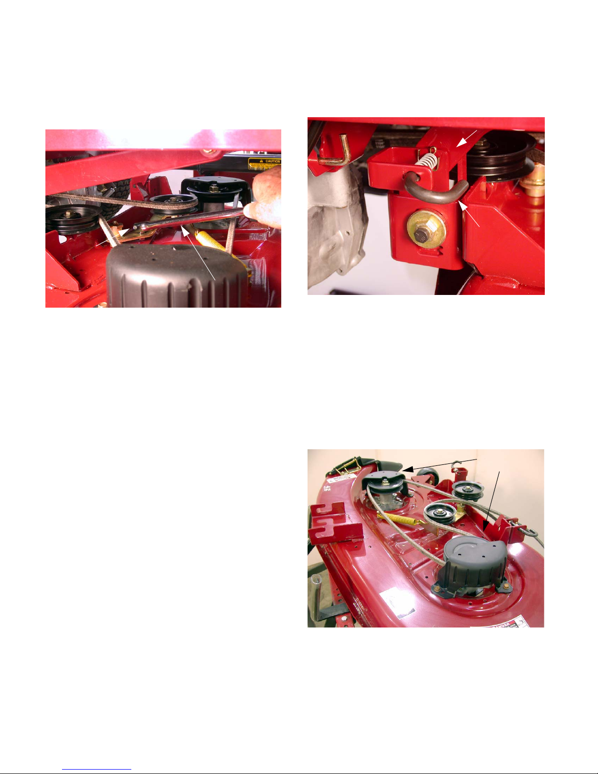
2. PTO / DECK BELT REPLACEMENT
2.1. Insert a 1/2” breaker bar into the square hole in
the tensioner arm located on top of the deck.
See Figure 2.1.
Idler arm
1/2” Breaker bar
Figure 2.1
2.2. Pivot the tensioner arm and pulley to slacken the
belt.
3. DECK REMOVAL
3.1. Release the deck J pins from the rear hanger
arms. See Figure 3.1.
Deck hanger rod
“J” Pin
Figure 3.1
3.2. Slide the deck forward until the front stabilizer
bar can be lifted away from the front mounting
bracket.
2.3. Remove the belt from the two stationary idler
pulleys and spindle pulleys.
NOTE: The spindle covers do not need to be
removed.
2.4. Remove the belt from the clutch.
3.3. Slide the deck out from underneath the unit.
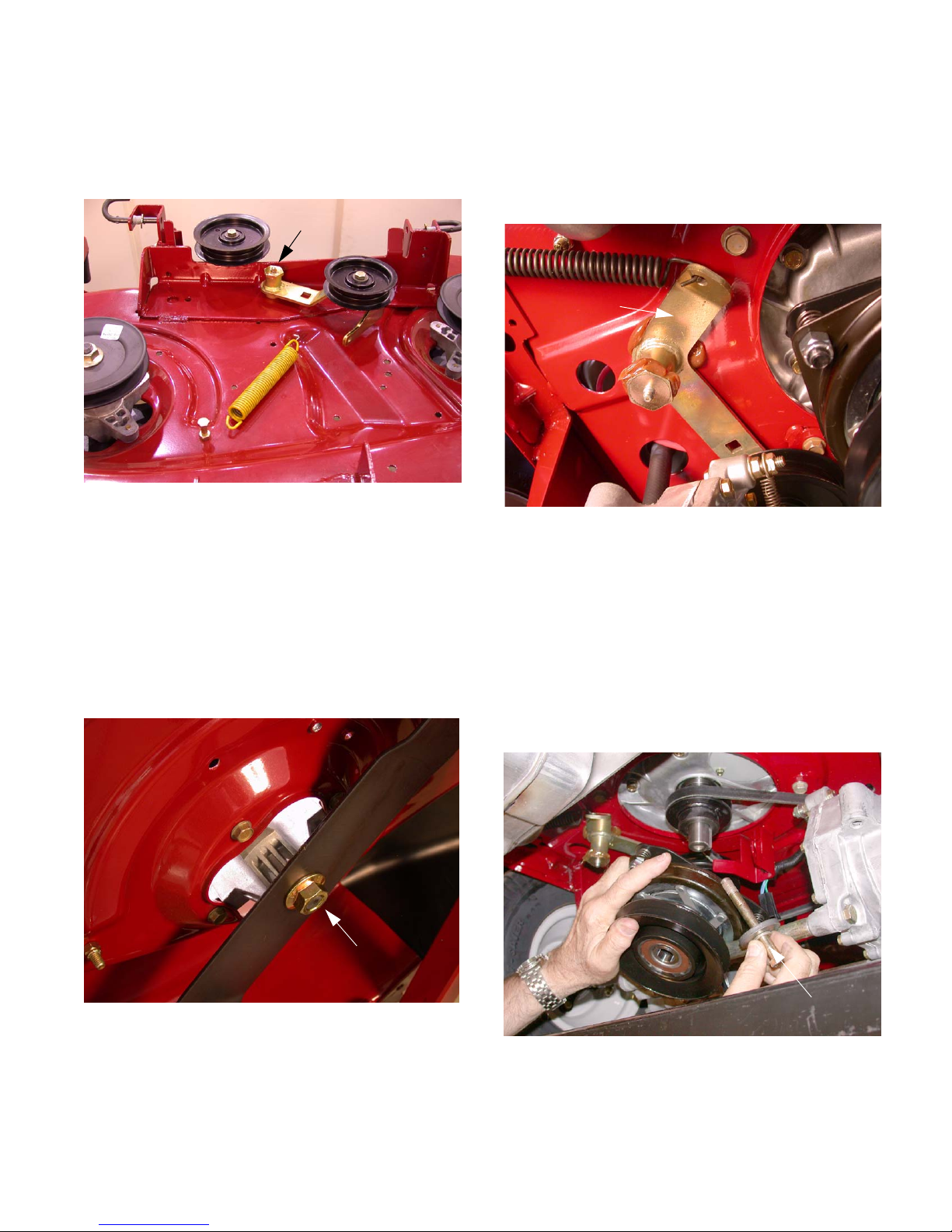
4. BLADE DRIVE BELT REMOVAL
4.1. Remove the deck from the unit.
4.2. Remove both belt covers. These belt covers are
identical and interchangeable. See Figure 4.2.
Belt Covers
Figure 4.2
www.mymowerparts.com
4.3. Remove the belt from around the pulleys.
4.4. Install the new belt. A belt routing diagram label
is adhered to the deck housing.
5. IDLER ARM REMOVAL
2
For Discount White Outdoor Parts Call 606-678-9623 or 606-561-4983
5.1. Remove the cutting deck from the unit.
5.2. Remove the shoulder screw and hex lock nut
securing the idler to the deck housing. See Figure 5.2.
Idler
Figure 5.2
5.3. Remove the idler and inspect for wear or damage.
6. BLADE SPINDLE REMOVAL
6.1. Remove the deck from the unit.
7.1. Insert a 3/8” breaker bar into the square hole on
the tensioner arm.
7.2. Pull the breaker bar to the right until it can be
braced in position at the pivot point of the tensioner arm. See Figure 7.2.
Idler arm
Figure 7.2
7.3. Remove the belt from the transmission pulleys,
tensioner pulley and the crankshaft pulley. Belt
is part number 754-04043
6.2. Remove the spindle covers and blade drive belt.
6.3. Using an impact wrench, remove the hex flange
nut securing the blade to the spindle assembly.
See Figure 6.3.
Hex Flange Lock Nut
Figure 6.3
6.4. Remove the four hex washer head tapp screws
securing the spindle assembly to the deck housing.
7. DRIVE BELT REPLACEMENT
8. SERVICING ELECTRIC PTO CLUTCH
8.1. Using a small flat blade screwdriver, unplug the
electrical connector on the PTO clutch.
8.2. Using a 5/8” socket and an impact wrench,
remove the clutch bolt. See Figure 8.2.
Clutch Bolt
Figure 8.2
8.3. Lower the clutch off of the crankshaft.
8.4. Remove the crankshaft key.
www.mymowerparts.com
3
For Discount White Outdoor Parts Call 606-678-9623 or 606-561-4983
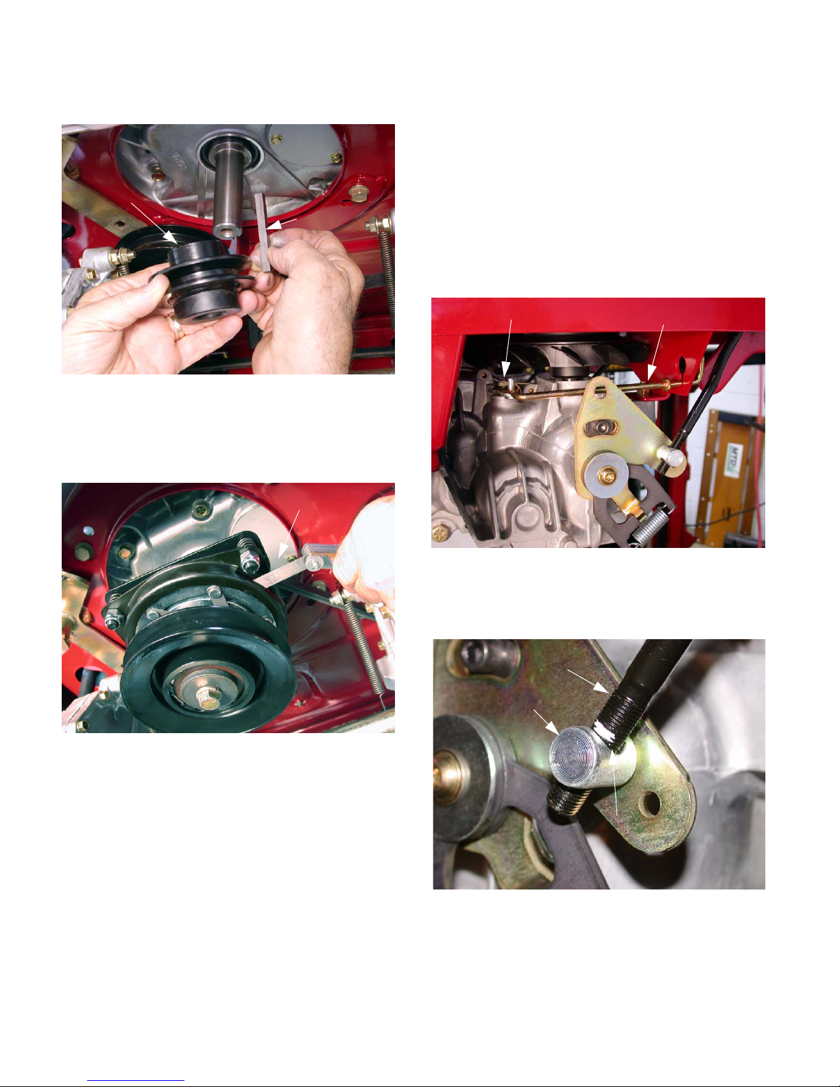
8.5. Remove the crankshaft pulley. See Figure 8.5.
Crankshaft pulley
Key
Figure 8.5
8.6. Use a 9/16” socket to adjust the air gap on the
clutch to between.010” and.015”.
See Figure 8.6.
.012 Feeler gage
9.3. Remove the belt from the transmission pulleys,
tensioner pulley and the crankshaft pulley.
9.4. Using a 3/4” socket and impact wrench, remove
the four lug nuts securing the rear wheel to the
axle hub.
NOTE: Insure the lap bar control rods and b rake
rods are not rubbing against the frame.
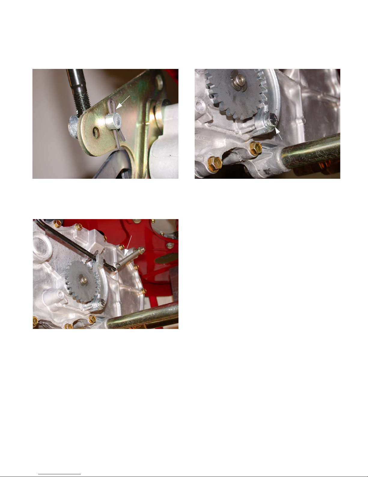
9.5. Remove the cotter pin securing the bypass rod
to the transmission bypass arm. Remove the
bypass rod. See Figure 9.5.
Cotter Pin
Bypass rod
Figure 8.6
NOTE: Clutch adjustment can be done with the
clutch in the unit. If a new clutch is being put in
the adjustment can be done on the bench.
9. TRANSMISSION REPLACEMENT
9.1. Insert a 1/2” breaker bar into the square hole on
the tensioner arm.
9.2. Pull the breaker bar to the right until it can be
braced in position at the pivot point of the tensioner arm.
Figure 9.5
9.6. Mark the lap bar control rod threads near the ferrule. See Figure 9.6.
Control Rod
Ferrule
Marking Paint
Figure 9.6
www.mymowerparts.com
4
For Discount White Outdoor Parts Call 606-678-9623 or 606-561-4983
9.7. Remove the hairpin securing the lap bar control
rod ferrule to the transmission return assembly. See Figure 9.7.
Hairpin
Figure 9.7
9.8. Disconnect the brake return spring from the
brake arm. See Figure 9.8.
9.9. Remove the bolt securing the brake arm to the
transmission using a 7/16” socket.
See Figure 9.9.
Brake Arm Bolt
Figure 9.9
NOTE: A spacer is located between the brake
arm and transmission housing.
Figure 9.8
Brake Return Spring
NOTE: During installation, the bottom ridge of
the brake arm needs to be below the embossment on the transmission housing. Improper
installation will prevent the brake from engaging.
9.10. Remove both bolts securing the tubular transmission brace using a 5/8” socket.
NOTE: When installing the brace bolts use loctite 242.
9.1 1. Remove the front transmission mounting bolt
using a 1/2” wrench and a 1/2” socket.
NOTE: Secure the transmission or use another
technician to support the transmission while performing the next step.
www.mymowerparts.com
5
For Discount White Outdoor Parts Call 606-678-9623 or 606-561-4983
9.12. Remove both transmission mounting bolts
securing the transmission to the mounting
bracket using two 1/2” wrenches.
See Figure 9.12.
Transmission Mounting Bolts
Figure 9.12
9.13. Rotate the transmission out and down until the
fan is clear of the front transmission mounting
bracket, and remove it from the frame.
9.14. Installation notes:
• Lift transmission into place a nd start a ll threaded
fasteners before tightening any individual fasteners.
10. STEERING LINKAGE: ADJUSTMENT
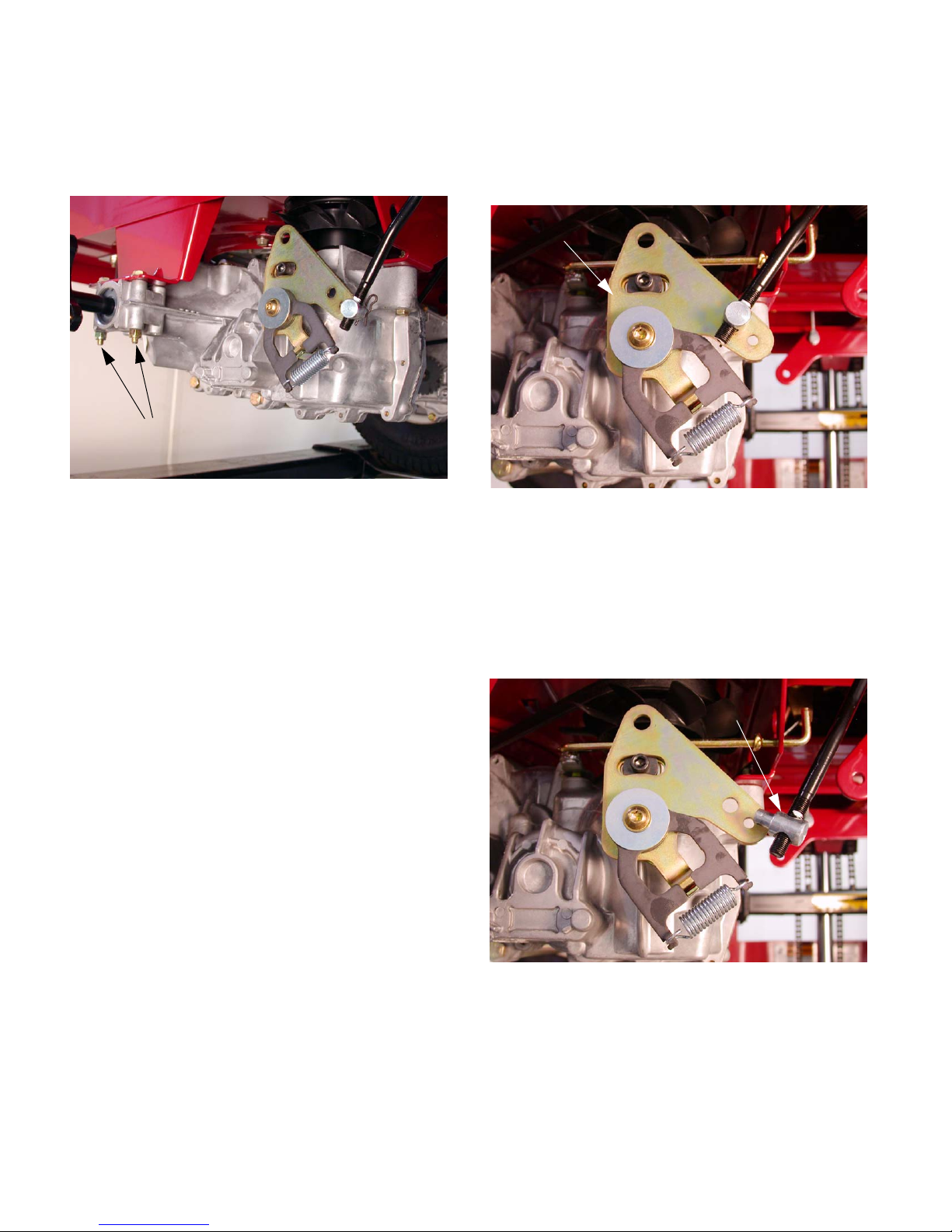
10.1. Begin to adjust the steering by confirming that
both hydros are correctly adjusted for neutral
control. See Figure 10.1.
Neutral Return Assembly
Figure 10.1
10.2. Lift and safely support the rear of the mower.
10.3. Disconnect the ferrule at the hydro end of each
lap bar control rod from the neutral return
assembly on each of the hydros. The ferrules
are secured to the neutral return assemblies with
hairpin clips. See Figure 10.3.
• Install the axle horn bolts from the top down,
tighten nuts to a torque of 90-120 in-lbs.
• Install the torque bracket bolt from the bottom
up, and tighten the nut to a torque of 90-120 inlbs.
• Install the bolts in the tubular transmission
braces and tighten them to a torque of 90-120 inlbs.
• The remainder of the installation process consists of reversing the removal process.
• Tighten the lug nuts to a torque of 350-500 inlbs.
• Tighten the center wheel hub nut to 100-160 Ft.
Lbs.
Ferrule
Figure 10.3
NOTE: In the course of normal service, it is very
unusual for the neutral return assemblies to
require adjustment unless someone has prev iously tampered with it. It is necessary to check
the adjustment because the rest of the proce-
www.mymowerparts.com
6
 Loading...