

Page 1
White Oak Tools, LLC
User Manual # 108000-06
Page 2
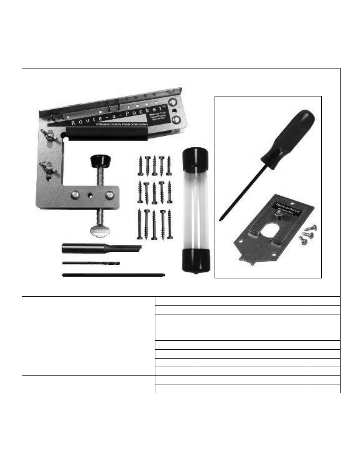
Route-a-PocketTM Components
i
White Oak Tools, LLC
Route-a-PocketTM
Hardware
Quantity
Component
Part #
1
Route-a-PocketTM assembly
101000
1
Route-a-PocketTM router bit
106008 1 9/64” dia. drill bit
104001
1
#2 ball tip square drive driver
106010
1
Storage tube
106012 5 #7 x 1” pocket screw
106060
5
#7 x 1-1/4” pocket screw
106061
5
#7 x 1-1/2” pocket screw
106062
Optional Hardware
1
Mounting plate with (3) screws
101001
1
#2 ball tip square drive screwdriver
106009
Patent Pending
Optional
Hardware
Page 3
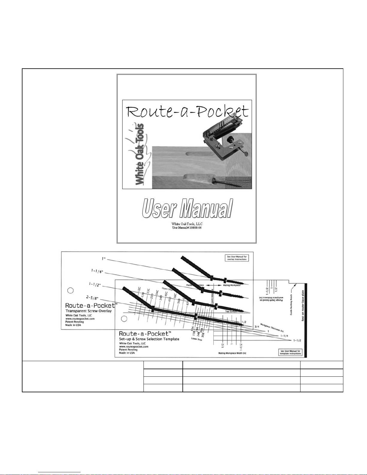
Route-a-PocketTM Components
www.routeapocket.com
ii
Route-a-PocketTM
User Manual, Overlay &
Template
Quantity
Component
Part # 1 User Manual
108000
1
Set-up & Screw Selection Template
108001
1
Transparent Screw Overlay
108002
Page 4
Route-a-PocketTM Components
iii
White Oak Tools, LLC
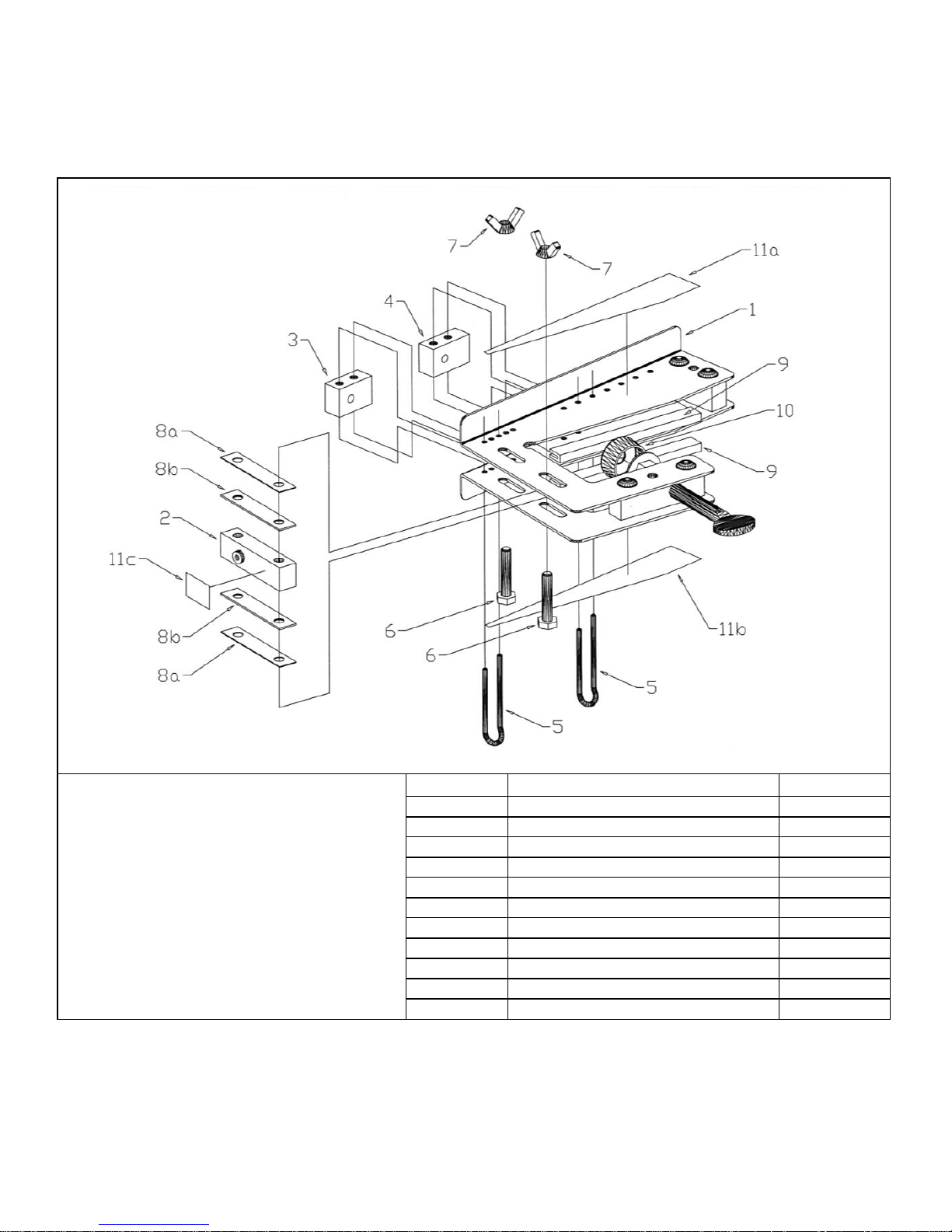
Exploded View of Main Assembly
Item #
Part Name
Part #
1
Body assembly
101002
2
Drill guide assembly
101003
3
Lower stop block assembly
101004
4
Upper stop block assembly
101005
5
Retaining pin
106002
6
Hex bolt
102002 7 Wing Nut
102003
8
Shim (set of 4)
106004
9
Edge pad
106003
10
Clamp pad
106011
11
Label (set of 4)
108003
Page 5
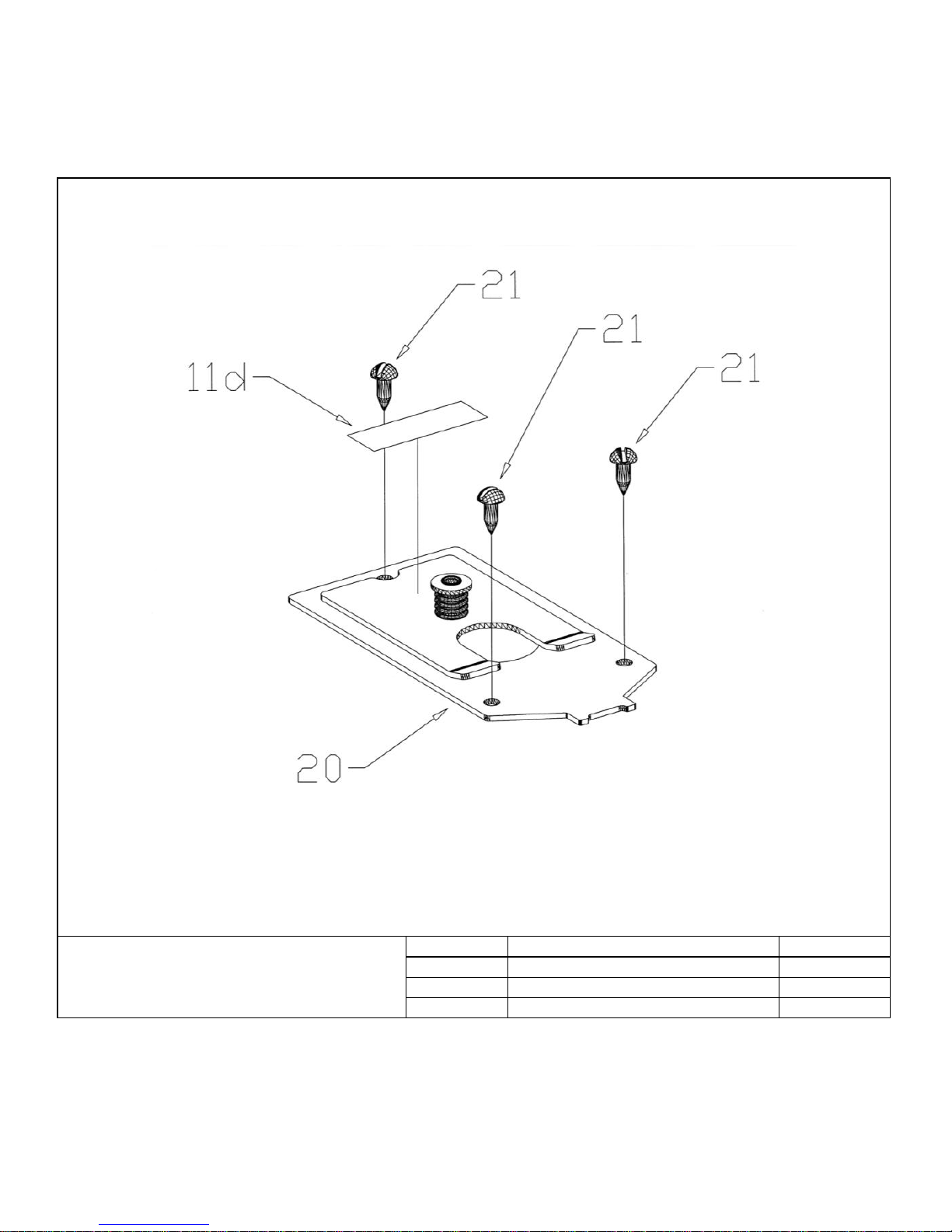
Route-a-PocketTM Components
www.routeapocket.com
iv
Exploded View of Optional
Mounting Plate
Item #
Part Name
Part #
11
Label (set of 4)
108003
20
Mounting plate assembly
101001
21
Wood screws
102007
Page 6

Table of Contents & Introduction
v
White Oak Tools, LLC
Table of Contents
Section
Page #
Route-a-PocketTM Components
i
Table of Contents & Introduction
v
Route-a-PocketTM Specifications & Required Tools
1
Using the Template & Adjusting the Stops
2
Setting the Drill Bushing Height
7
Plunge Router & Power Drill Set-up
8
Machining Procedure
11
Aligning the Pilot Hole with the Pocket
18
Assembling the Joint
20
Using the Optional Mounting Plate
24
Joining 2 or More Route-a-Pockets & Maintenance
27
Customer Support
28
Introduction:
Thank you for choosing Route-a-PocketTM. The Route-a-PocketTM has been designed to
produce professional quality pocket screw joinery with your plunge router and power
drill. Please take the time to read and understand this user manual in its entirety. By
doing so, you’ll be introduced to all the jig’s features. We also suggest you practice
using the Route-a-PocketTM on test pieces prior to using it on your next project. This step
will build your confidence with the jig and ensure you have configured the Route-aPocketTM to produce the anticipated results. Finally, don’t forget to visit the Route-aPocketTM website (www.routeapocket.com). The site includes an interactive “Set-up &
Screw Selection Template” along with other useful resources.
Page 7

Route-a-PocketTM Specifications & Required Tools
www.routeapocket.com
1
Route-a-PocketTM Specifications
Allowable Workpiece Thickness
Minimum: 1/2"
Maximum: 1-1/2”
Pocket Width
3/8”
Pocket Length
Minimum: 1/2”
Maximum: 4-1/8”
Pilot Hole Diameter
9/64”
Pocket & Pilot Hole Angle
10°
Screw Grip Length
Minimum: 7/16”
Maximum: 1-1/8”
Required Tools:
Plunge Router
For your safety, it is important that you select a good quality and well maintained plunge
router for use with the Route-a-PocketTM. Selecting the proper plunge router will also
make it easy to achieve the quality results you expect. The plunge router must accept a
router bit with a 1/2” shank and should have a plunge stroke of at least 2-3/8”. The
maximum suggested plunge router horsepower rating is 2-1/4.
Guide Bushing
The guide bushing must be compatible with your plunge router and have an outside
diameter of 3/4". The collar length should be 1/2" or longer.
Power drill
The power drill used to drive the pocket screws should be equipped with an adjustable
clutch.
Page 8
Using the Template & Adjusting the Stops
2
White Oak Tools, LLC
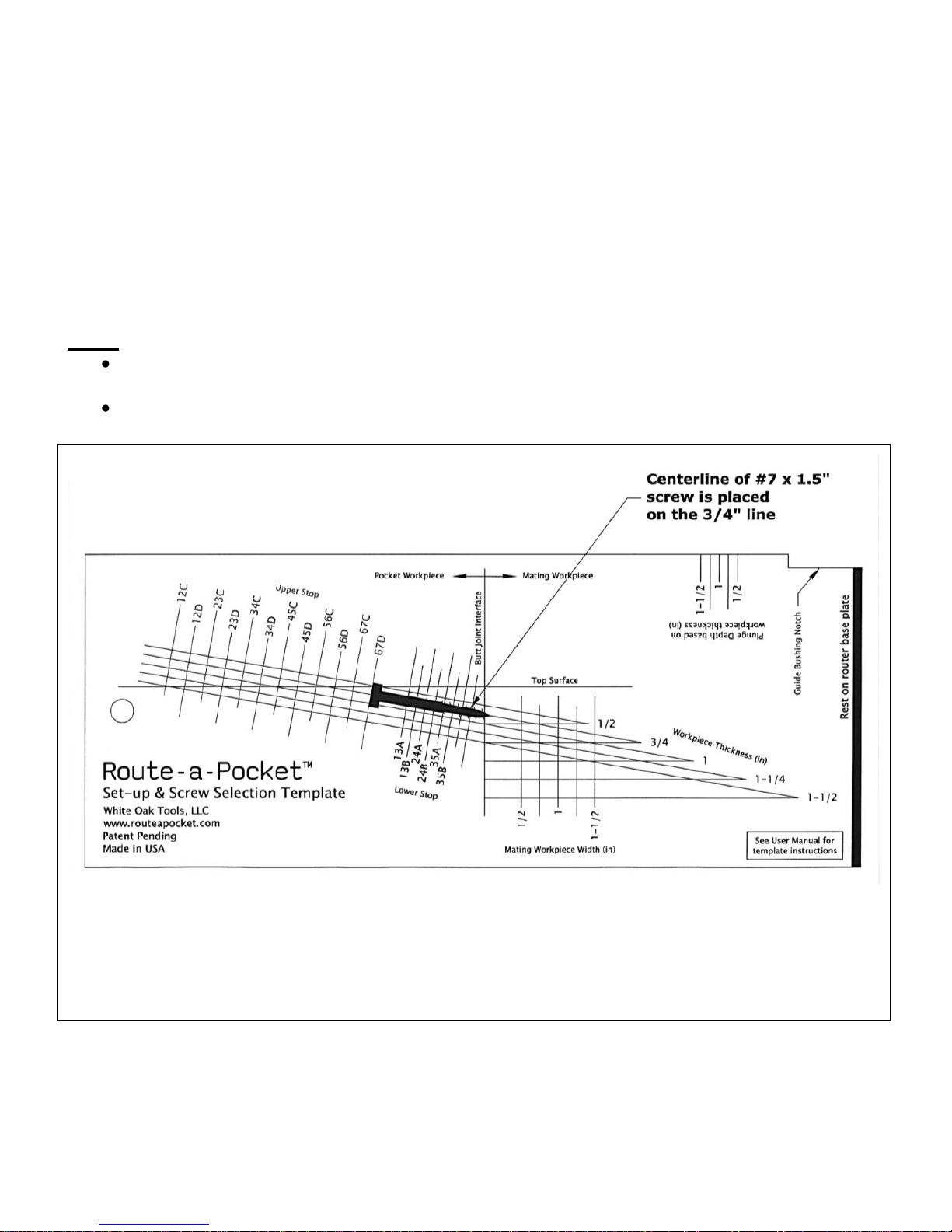
Included with your Route-a-PocketTM is the Set-up & Screw Selection Template. This
template makes it easy to select the appropriate screw and Route-a-PocketTM settings for
your joining application. The template may be used by placing an actual screw on the
card or by overlaying the transparent screw overlay, also included, on the card. This
section describes the process.
Notes:
For most applications, the suggested Route-a-Pocket settings are listed on the back cover of this
User Manual.
An interactive Set-up & Screw Selection Template is available on-line at www.routeapocket.com.
Figure 1a - Caution, template shown above is not full scale
Place the centerline of the desired screw on the sloped line corresponding to the
workpiece thickness. In this example, a #7 x 1-1/2” long screw is to be used with a 3/4”
thick workpiece.
Page 9
Using the Template & Adjusting the Stops
www.routeapocket.com
3
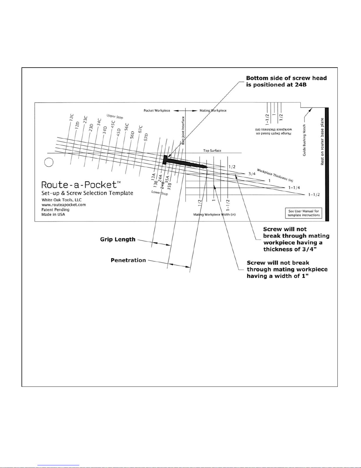
Figure 1b – Caution, template shown above is not full scale
Choose the lower stop position by sliding the screw along the sloped line and align the
bottom side of the screw head with the lower stop position that provides the desired grip
length and penetration. In this example, the screw is aligned with 24B.
Confirm that the screw penetration does not exceed the width or thickness of the mating
workpiece and adjust if necessary. In this example, the screw will not break through a
mating workpiece that is at least 1” wide and 3/4” thick
Record the selected lower stop position. In this example, 24B is recorded.
Page 10
Using the Template & Adjusting the Stops
4
White Oak Tools, LLC
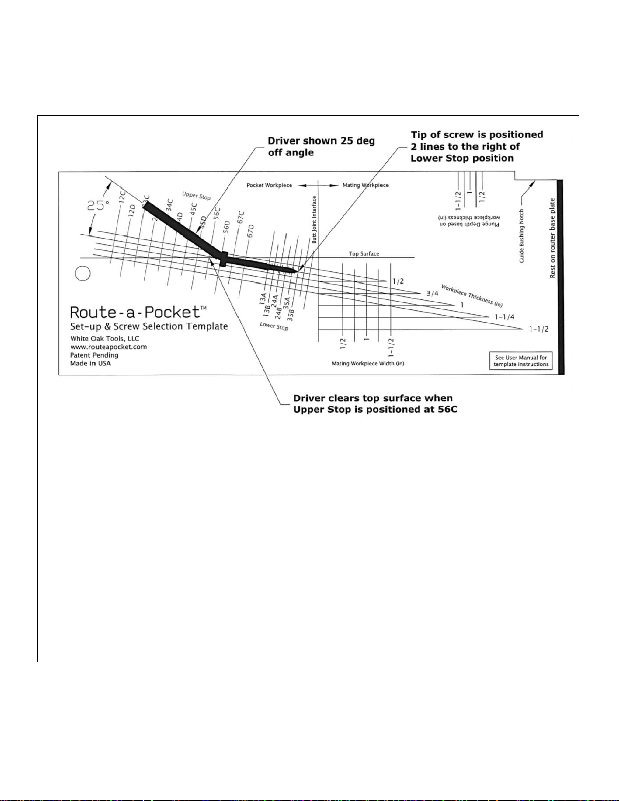
Figure 1c – Caution, template shown above is not full scale
Choose the upper stop position by repositioning the screw along the sloped line until the
tip of the screw is aligned with the second line to the right of the previously recorded
lower stop position. Positioning the tip at this location represents the tip of the screw
entering the pilot hole 1/4”. In this example, the tip of the screw is aligned with 35B.
Observe the upper stop position corresponding with the first line to the left of the screw
head. Confirm that there is adequate driver access and adjust if necessary. In this
example, the driver has adequate access when used at 25° off angle and the upper stop is
positioned at 56C.
Record the selected upper stop position. In this example, 56C is recorded.
Page 11
Using the Template & Adjusting the Stops
www.routeapocket.com
5
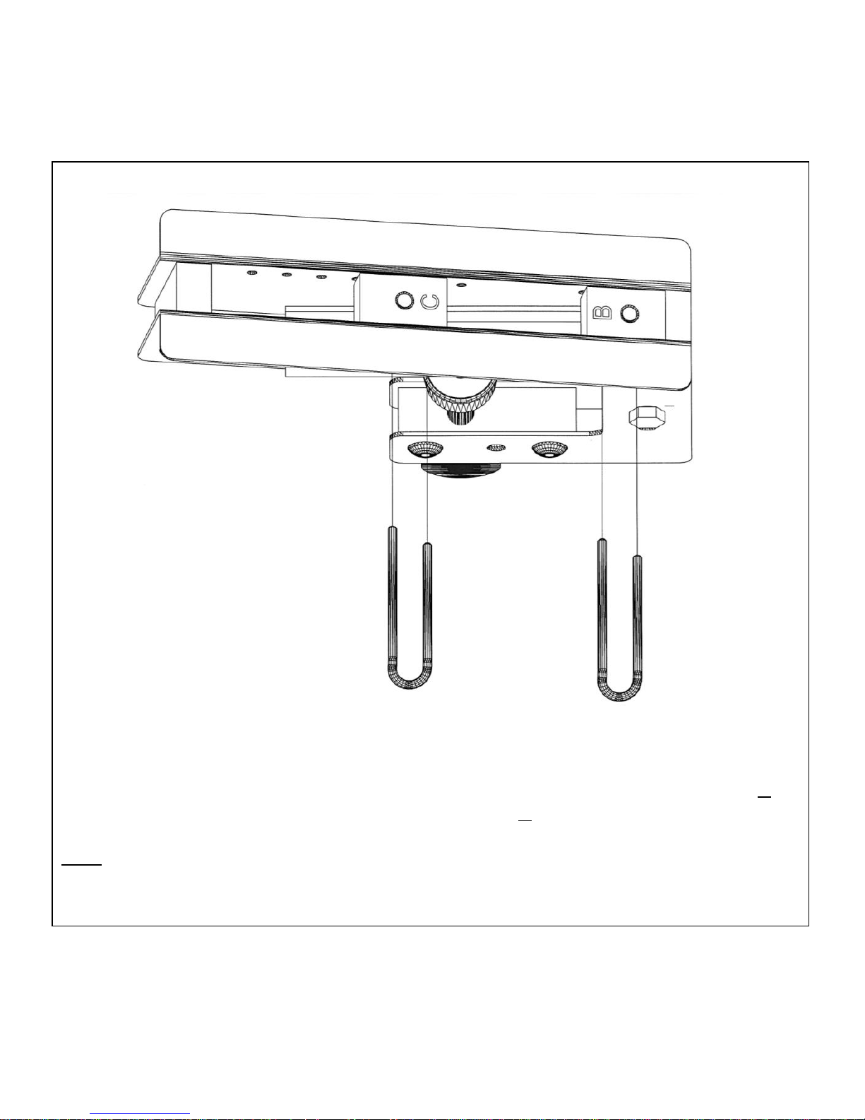
Figure 1d
Remove the pins and orient the stop blocks with the recorded stop block letters visible
from above. In this example, the lower stop block is oriented to the “B” position (24B).
The upper stop block is oriented to the “C” position (56C).
Note: The stop block letters must be oriented right side up when read from the drill guide end of the
Route-a-PocketTM. In this example, stop block letters “A” and “D” are hidden from view on the reverse side
of the stop blocks.
Page 12
Using the Template & Adjusting the Stops
6
White Oak Tools, LLC
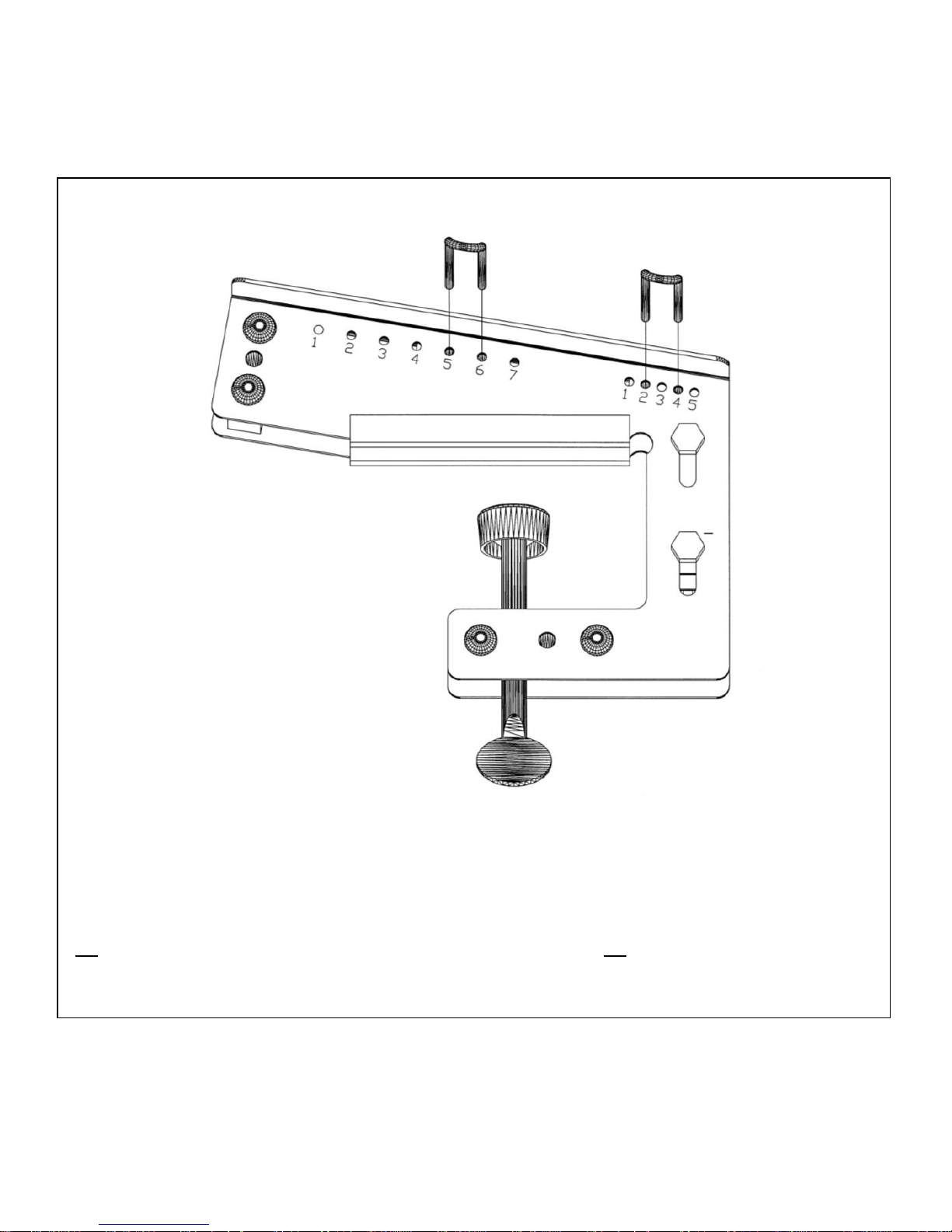
Figure 1e
Insert the pins through the recorded hole numbers making sure both legs pass through its
respective stop block. In this example, the lower pin is inserted through holes 2 & 4
(24B), while the upper pin is inserted through holes 5 & 6 (56C).
Page 13
Setting the Drill Bushing Height
www.routeapocket.com
7
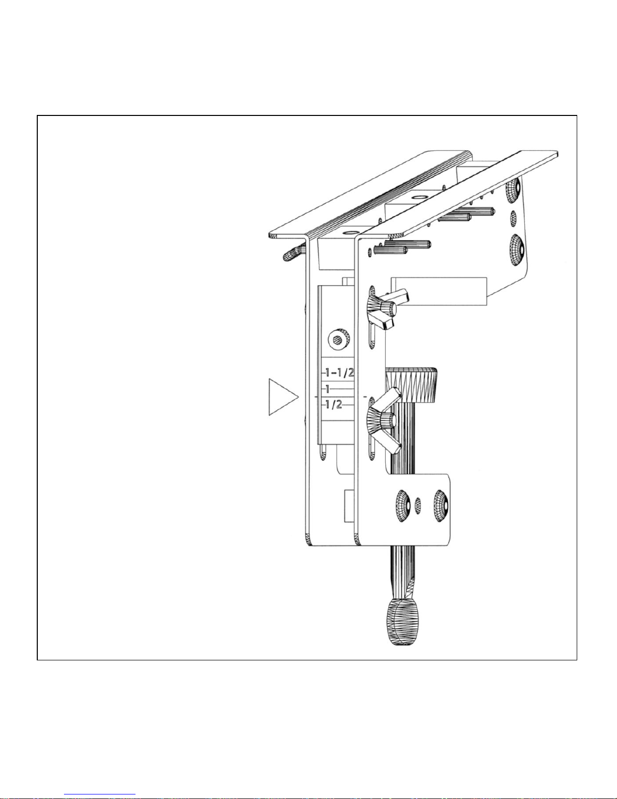
Figure 2a
Loosen the 2 wing nuts.
Slide the drill guide and scale
until the index (small slits on
each side plate) is aligned with
the mark corresponding to the
workpiece thickness. In this
example, the index is aligned
with 3/4”.
Tighten the 2 wing nuts.
Page 14
Plunge Router & Power drill Set-up
8
White Oak Tools, LLC
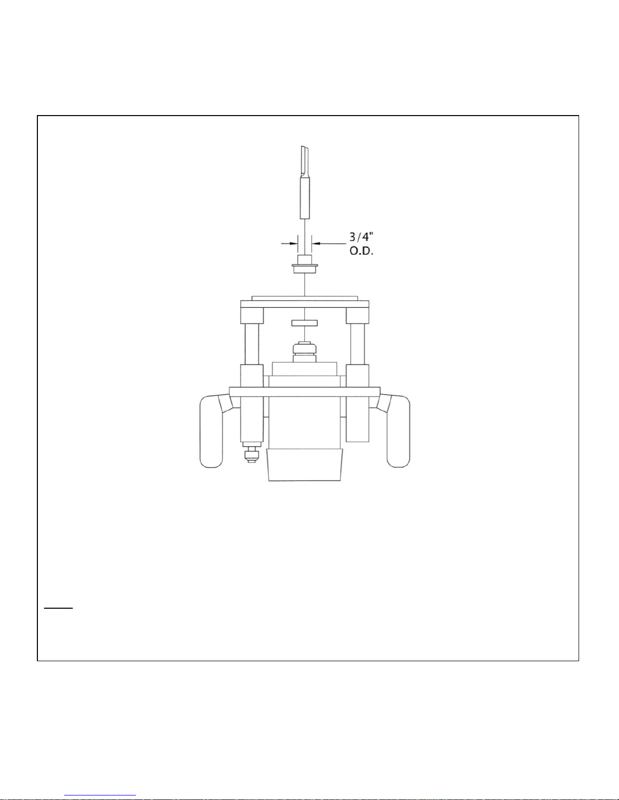
Figure 3a
Install a 3/4” outside diameter guide bushing (not included) and the supplied router bit
following the safety and operating instructions provided with your plunge router and
guide bushing.
Note: Confirm that the guide bushing is concentric (centered) to the router bit. If adjustment is necessary,
consult the operating/user manual that came with your router. Additional information on this topic can be
found in the section entitled Aligning the Pilot Hole with the Pocket.
Page 15
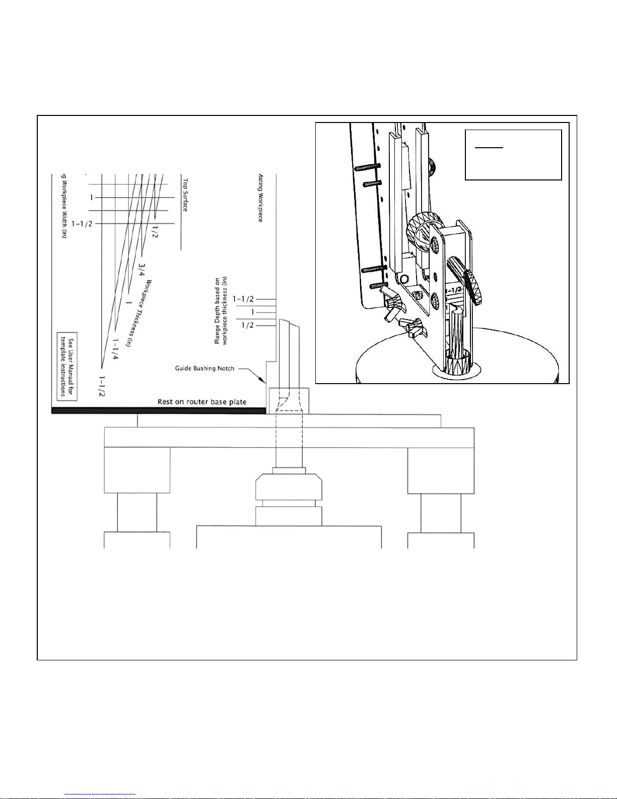
Plunge Router & Power drill Set-up
www.routeapocket.com
9
Figure 3b
Using the Set-up & Screw Selection Template, set the plunge depth by aligning the tip of
the router bit with the line corresponding to the workpiece thickness. On newer model
Route-a-Pockets, the plunge depth may be set using the scale located near the thumb
screw. In this example, the plunge depth has been set for a 3/4” workpiece.
Note: Scale not
included on
older models
Page 16
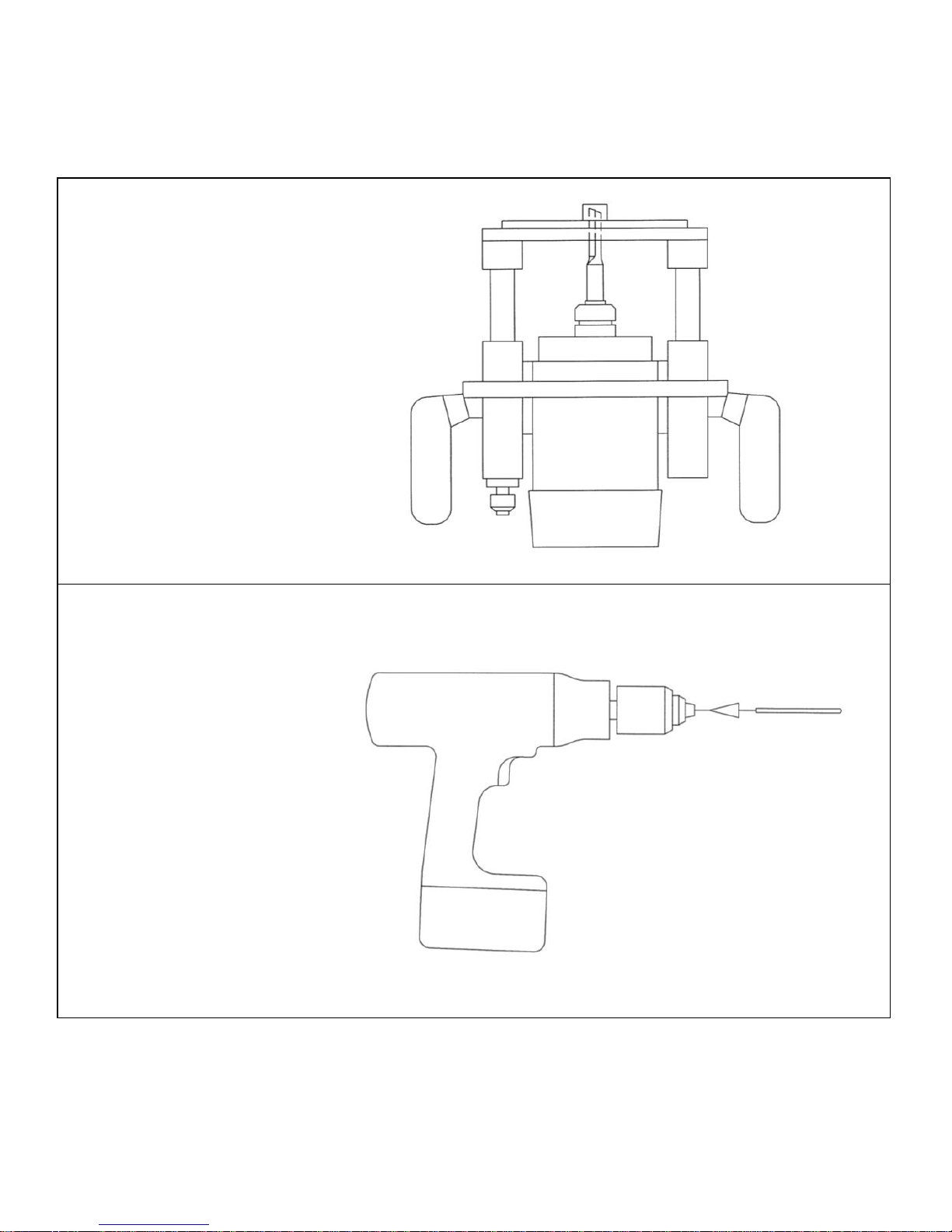
Plunge Router & Power Drill Set-up
10
White Oak Tools, LLC
Figure 3c
Adjust the plunge
stroke such that the
router bit fully retracts
into the guide bushing.
Confirm that the router
collet and bit do not
contact the guide
bushing or base plate
at any point through
the entire plunge
stroke.
Figure 3d
Install the supplied
9/64” diameter drill bit
following the safety
and operating
instructions provided
with your power drill.
Page 17
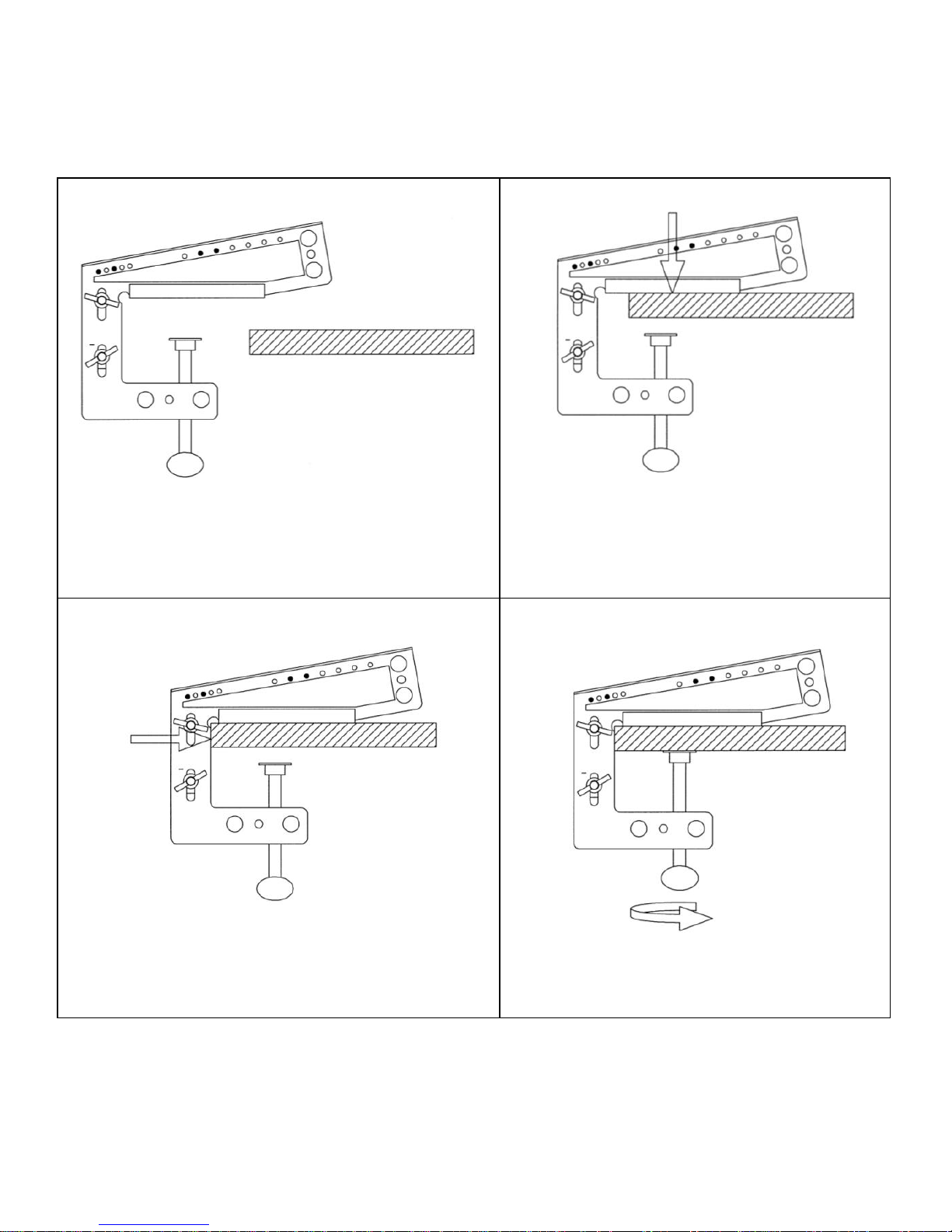
Machining Procedure
www.routeapocket.com
11
Figure 4a
Secure the workpiece to your workbench.
Position the Route-a-PocketTM near the
workpiece.
Figure 4b
Rest the Route-a-PocketTM on the
workpiece.
Figure 4c
Slide the Route-a-PocketTM over against the
edge of the workpiece.
Figure 4d
Securely tighten the thumb screw.
Page 18
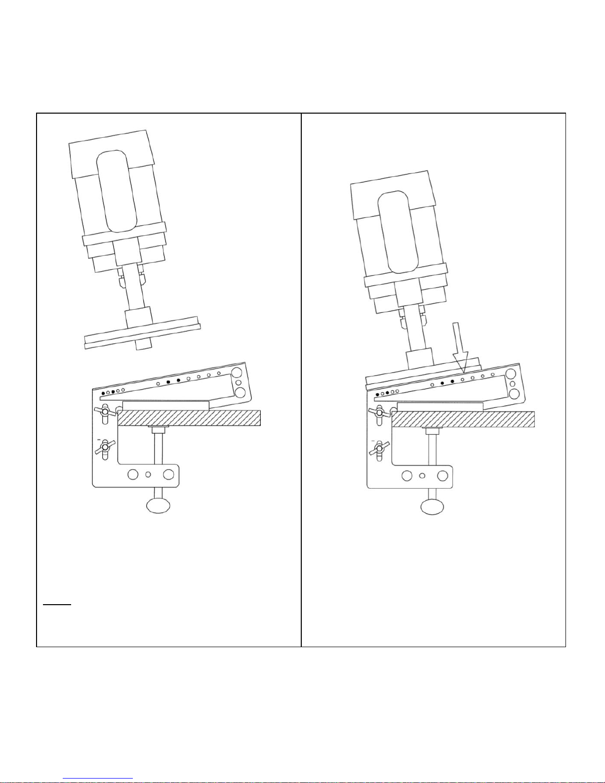
Machining Procedure
12
White Oak Tools, LLC
Figure 4e
Position the plunge router over the Routea-PocketTM.
Note: Follow the safety and operating instructions
that came with your plunge router.
Figure 4f
Rest the router base plate on the incline of
the Route-a-PocketTM. Make sure the guide
bushing is between the upper and lower
stops.
Page 19
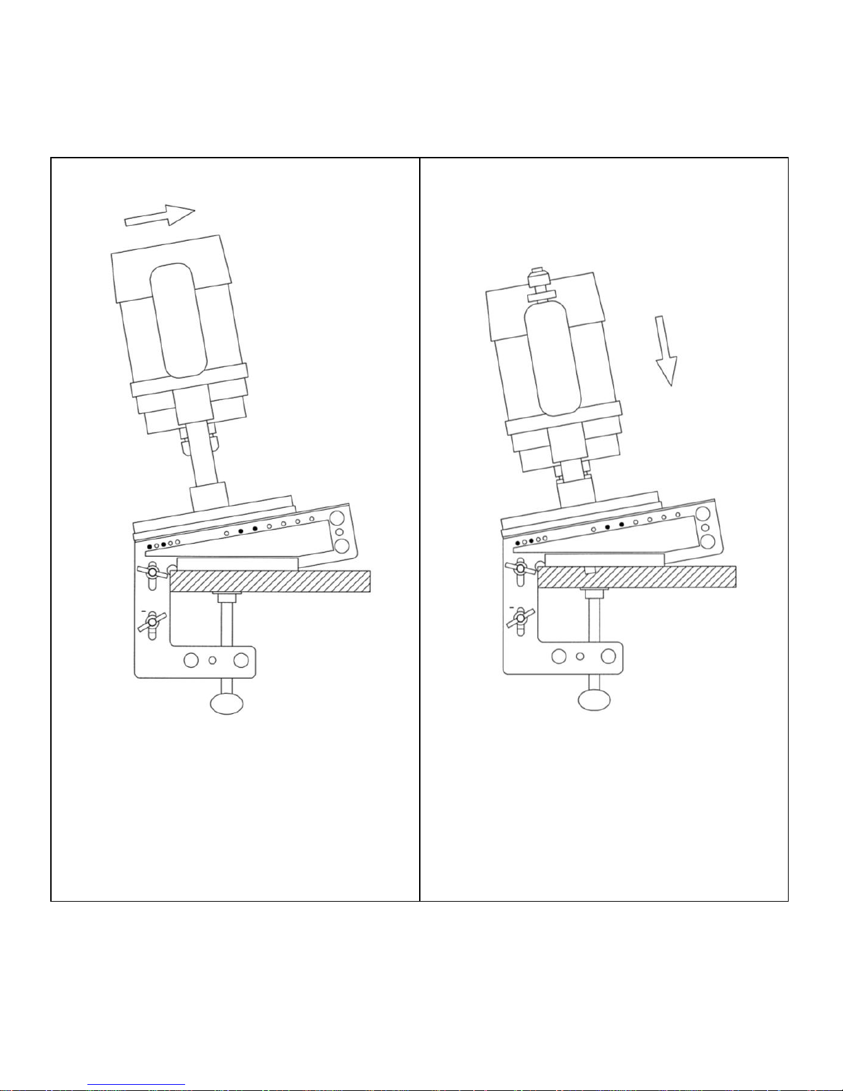
Machining Procedure
www.routeapocket.com
13
Figure 4g
Slide the router up the incline until the
guide bushing is against the upper stop.
Figure 4h
Turn the router on. Plunge the router to the
bottom of its plunge stroke.
Page 20
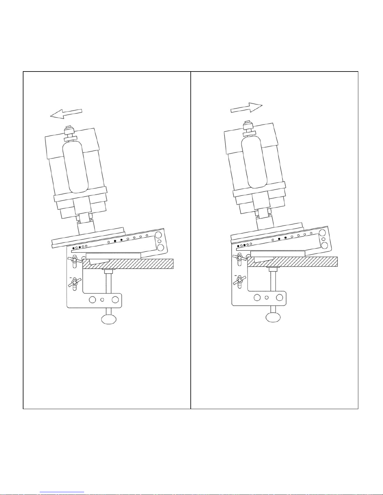
Machining Procedure
14
White Oak Tools, LLC
Figure 4i
Slide the router down the incline until the
guide bushing is against the lower stop.
Figure 4j
Slide the router back up the incline until
the guide bushing is against the upper stop.
This step clears the chips from the pocket.
Page 21
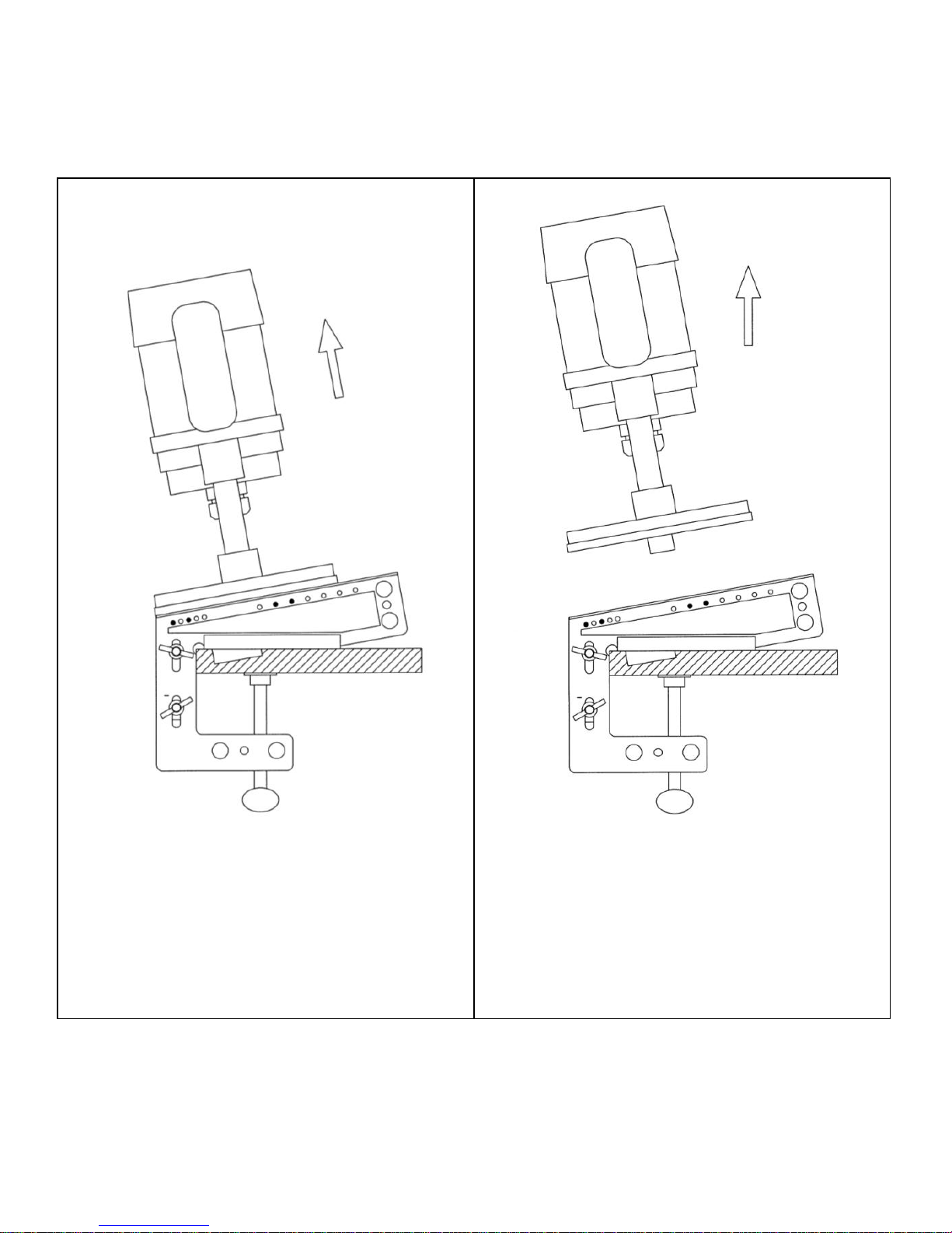
Machining Procedure
www.routeapocket.com
15
Figure 4k
Return the router to the top of its plunge
stroke.
Figure 4l
Turn the router off. Lift the router off the
Route-a-PocketTM.
Page 22
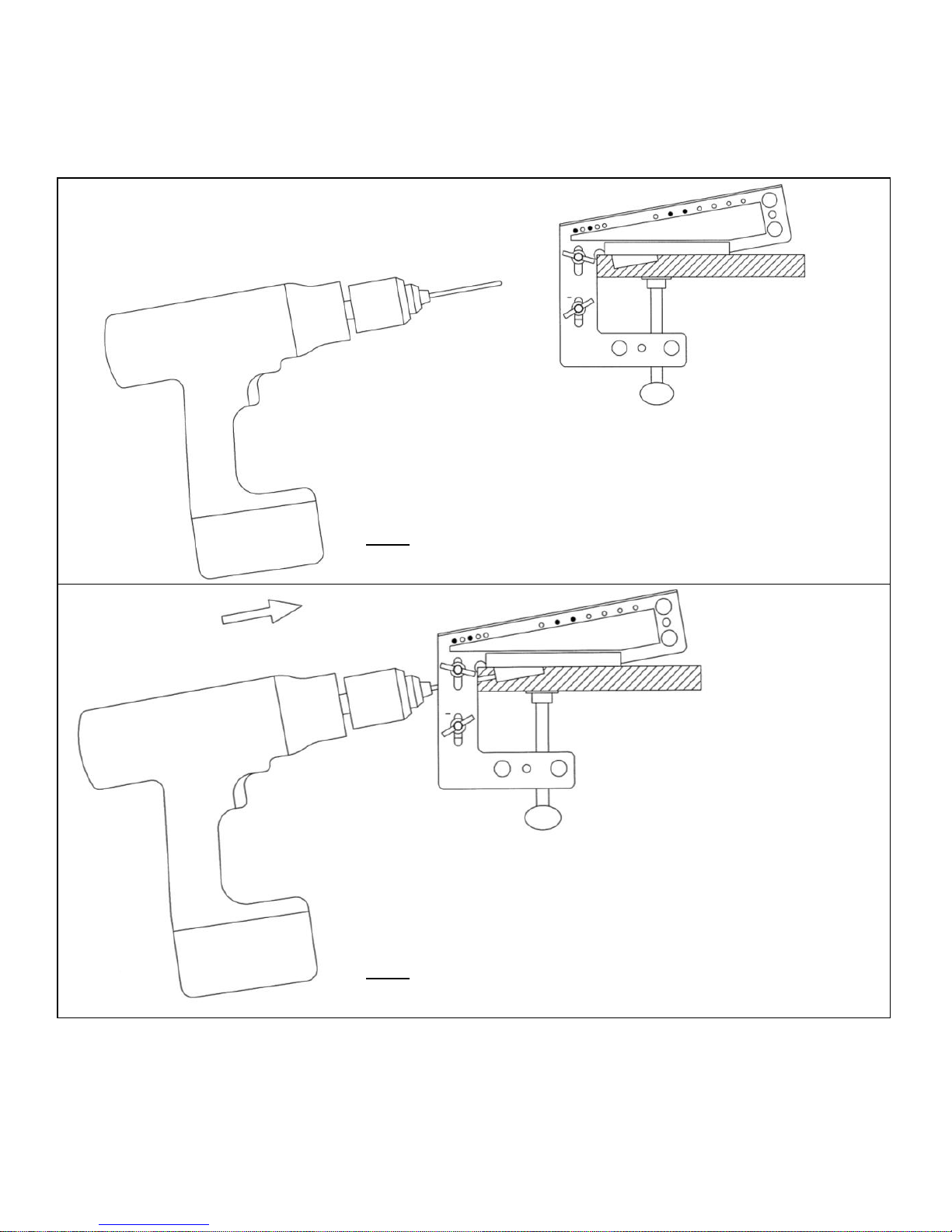
Machining Procedure
16
White Oak Tools, LLC
Figure 4m
Position the power drill near the front of the Route-aPocketTM.
Note: Follow the safety and operating instructions that came with
your power drill.
Figure 4n
Start the power drill. Guide the drill bit through the drill
bushing. Continue until the drill bit enters the pocket.
Note: It may be necessary to partially retract the drill bit, to clear
the chips, prior to the bit entering the pocket.
Page 23
Machining Procedure
www.routeapocket.com
17
Figure 4o
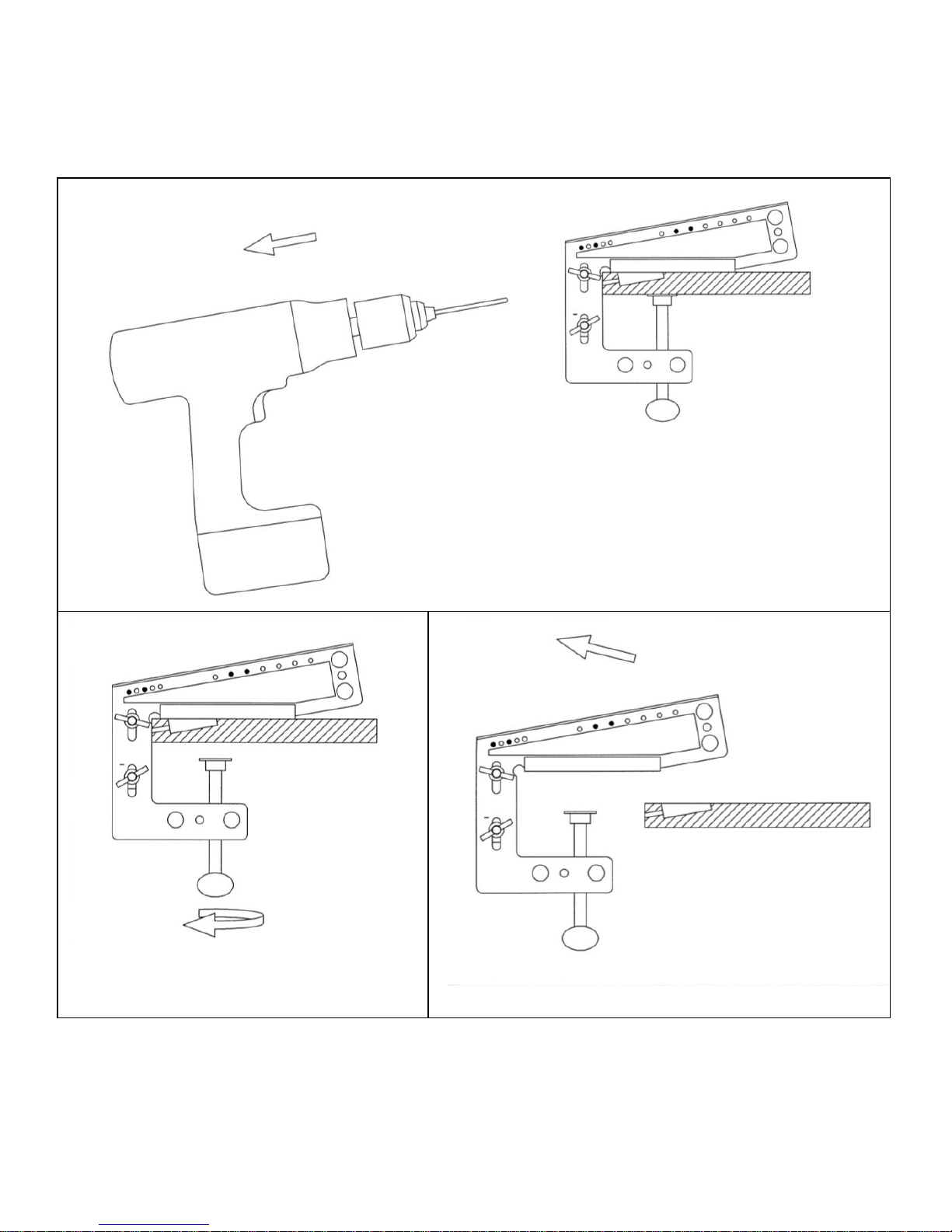
Back the drill bit out of the drill bushing. Stop
the power drill.
Figure 4p
Loosen the thumb screw.
Figure 4q
Remove the Route-a-PocketTM from the
workpiece.
Page 24
Aligning the Pilot Hole with the Pocket
18
White Oak Tools, LLC
Figure 5a
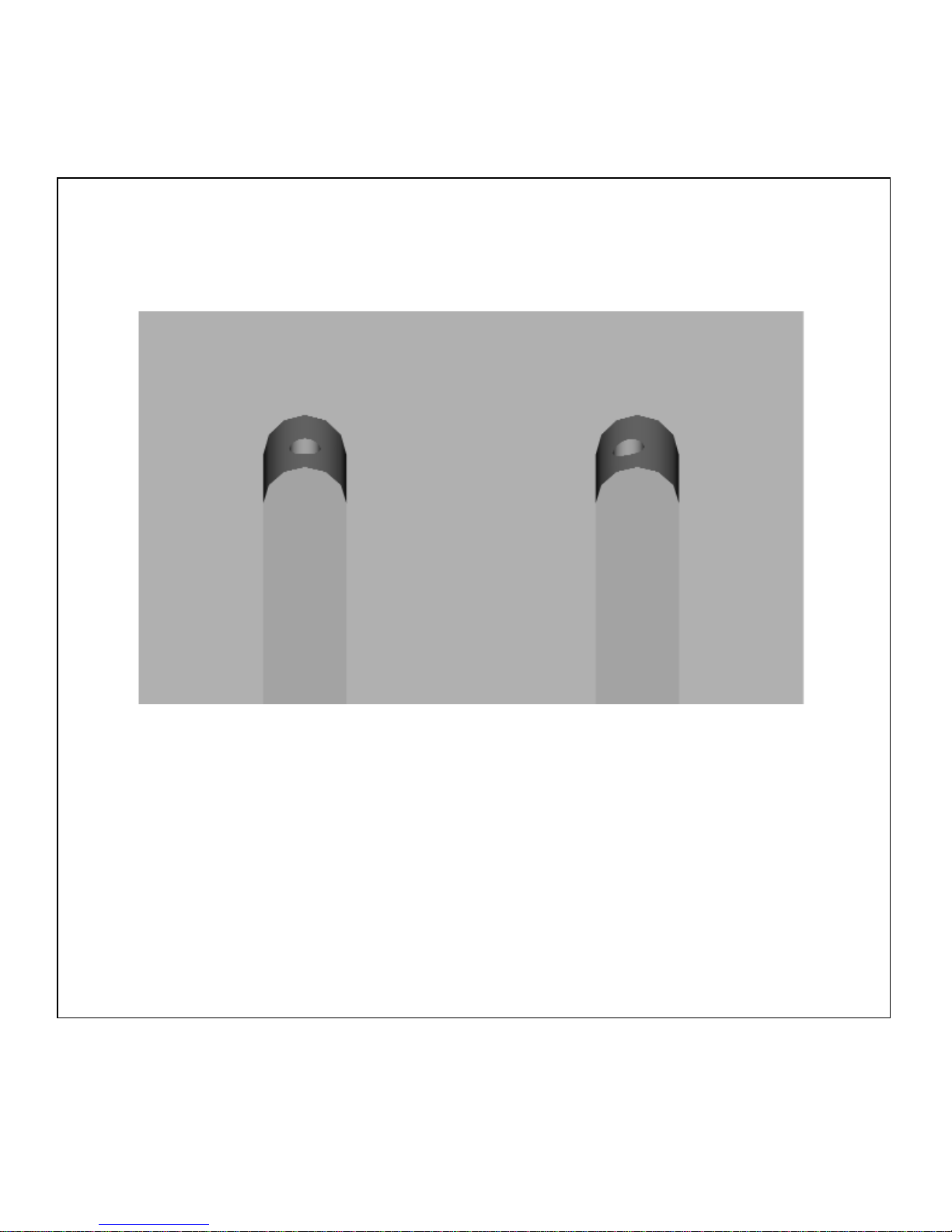
When looking into the pocket, the pilot hole should be centered in the pocket as shown at
“A”. If the pilot hole is off center, as shown at “B”, adjustment is required.
Start by confirming that the guide bushing is concentric (centered) to the router bit. If
they are not concentric to each other, consult the operating/user manual that came with
your plunge router and make the necessary adjustments.
A
B
Page 25
Aligning the Pilot Hole with the Pocket
www.routeapocket.com
19
Figure 5b
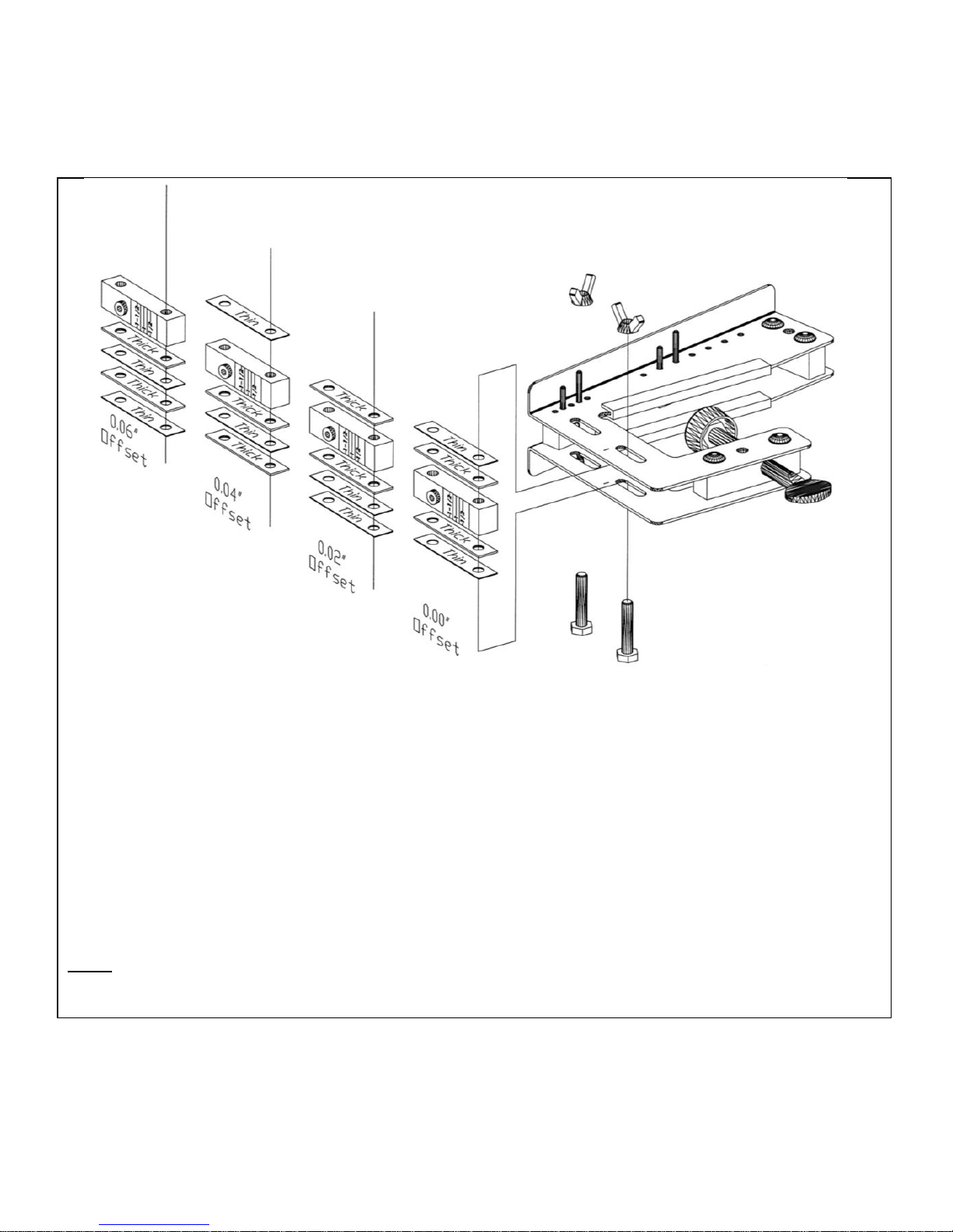
Often, it is difficult to make the guide bushing concentric with the router bit. For this
reason, your Route-a-PocketTM has been designed with shims on the sides of the drill
guide. These shims can be used to correct for misalignment between the pilot hole and
pocket. Your Route-a-PocketTM was shipped with (1) thin and (1) thick shim on each side
of the drill guide. By moving the shims from one side to the other, the pilot hole can be
shifted relative to the centerline of the pocket. Reposition the shims as needed to center
the pilot hole in the pocket. For reference, the thin shims are 0.02” thick and the thick
shims are 0.04” thick.
Note: To maintain proper side plate spacing, all (4) shims must be used at all times.
Page 26
Assembling the Joint
20
White Oak Tools, LLC
Figure 6a
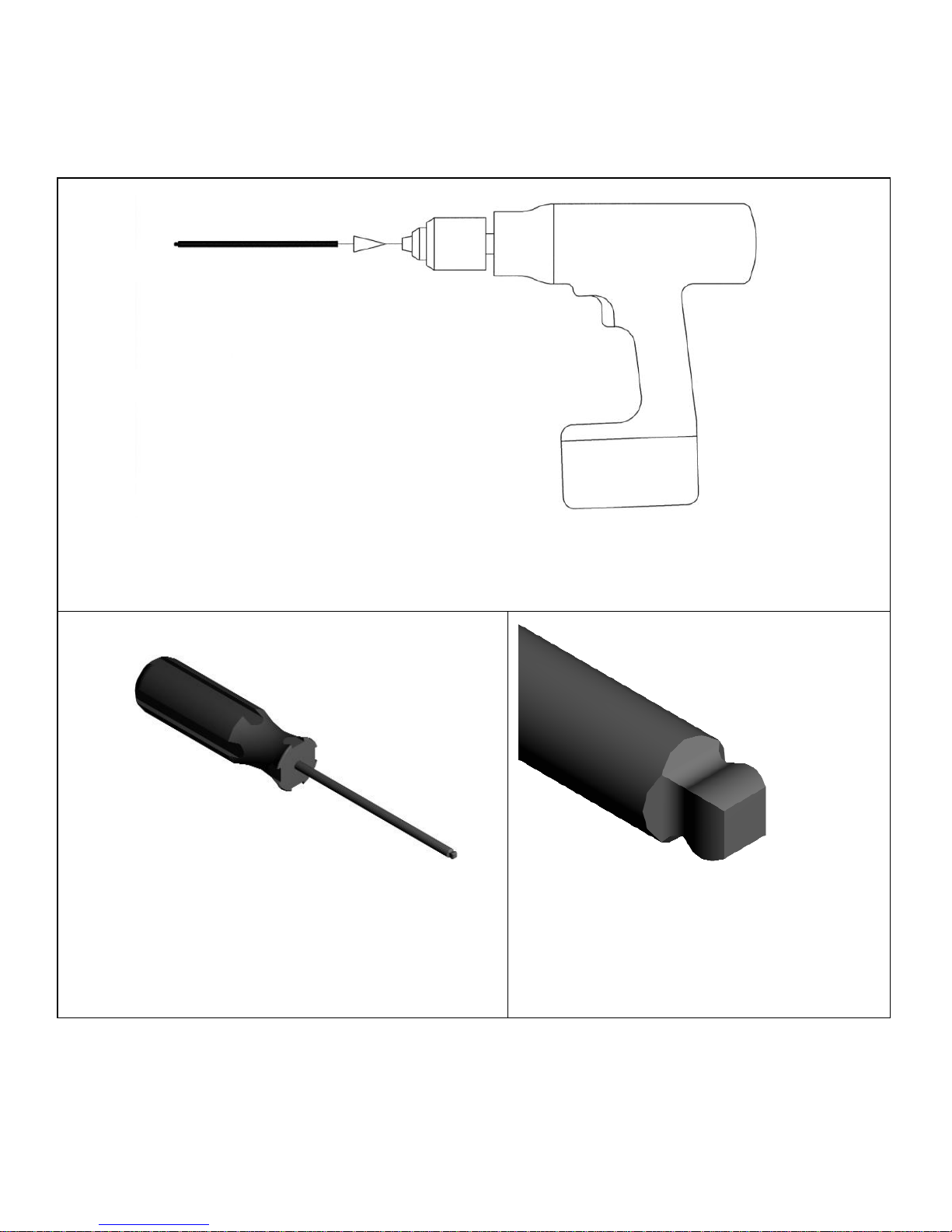
Install the supplied driver bit and adjust the clutch setting following the safety and
operating instructions provided with your power drill.
Figure 6b
Or select the optional screw driver.
Figure 6c
The driver bit and screwdriver are
designed with a #2 square drive ball tip
end. This feature allows the driver to
be used off angle up to 25°.
Page 27
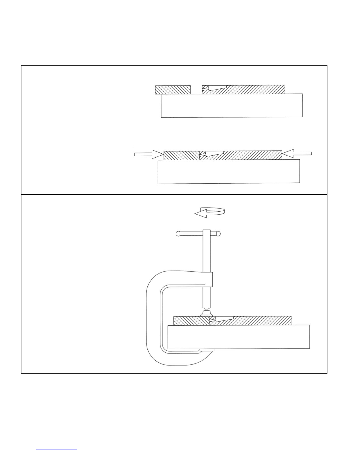
Assembling the Joint
www.routeapocket.com
21
Figure 6d
Rest the pocket workpiece
and its mating workpiece on
a flat work surface.
Figure 6e
If desired, add glue to the
joint interface. Align the
workpieces and push them
tightly together.
Figure 6f
Clamp both pieces to the
flat work surface.
Page 28
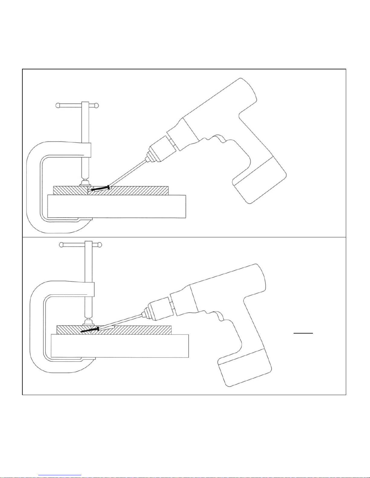
Assembling the Joint
22
White Oak Tools, LLC
Figure 6g
Position the
tip of the
screw in the
pilot hole.
Begin to
drive the
screw with
the driver off
angle, if
required.
Figure 6h
Drive the
screw home.
Note: The
driver can
become less
off angle as
the screw
approaches
home.
Page 29
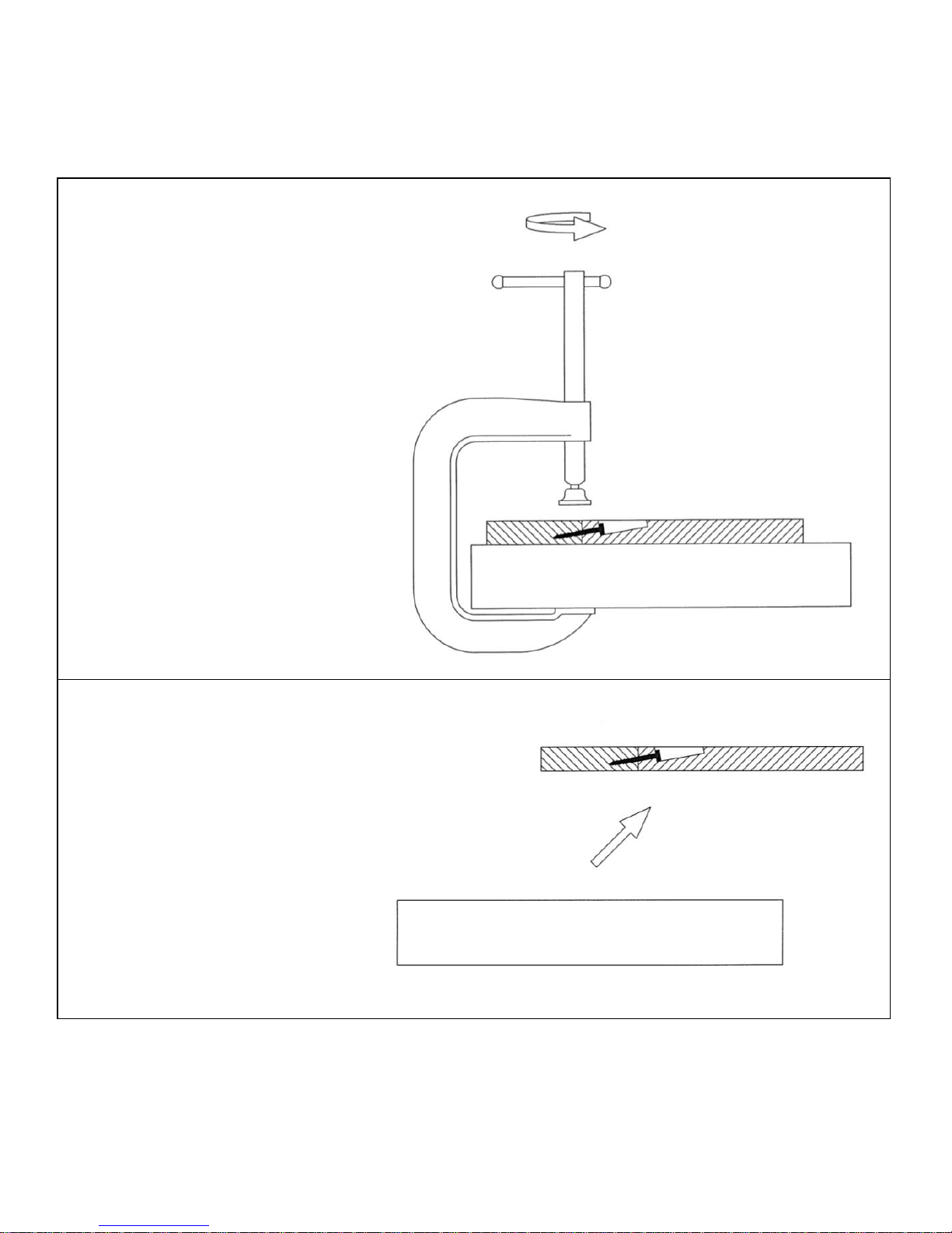
Assembling the Joint
www.routeapocket.com
23
Figure 6i
Remove the clamp.
Figure 6j
The joint is now complete.
Page 30
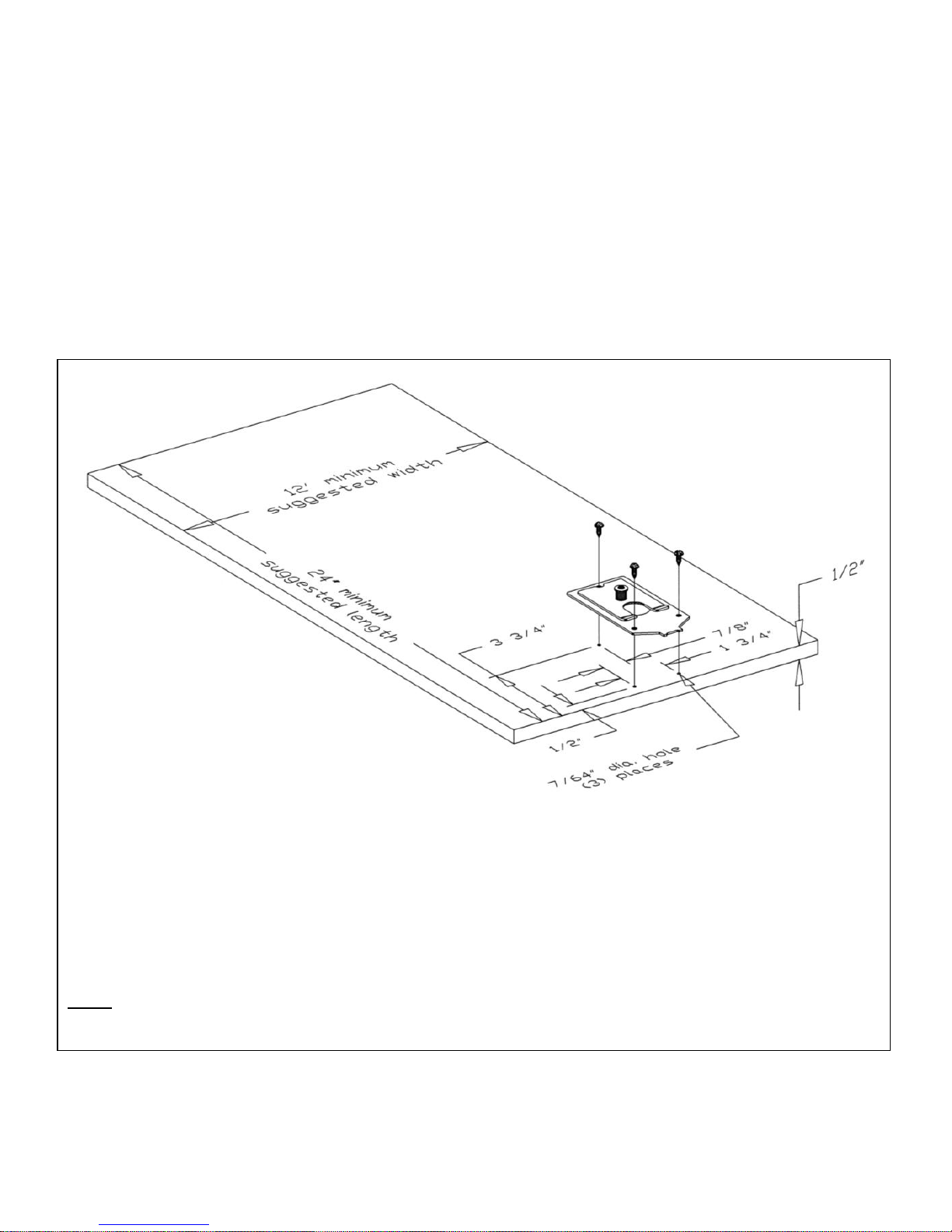
Using the Optional Mounting Plate
24
White Oak Tools, LLC
The optional Route-a-PocketTM mounting plate saves time when working with smaller
workpieces.
Once the Route-a-PocketTM is “snapped” into its mounting plate, tightening the Route-aPocket’s thumb screw not only secures the Route-a-PocketTM to the workpiece, it also
secures the workpiece to the workbench. This section describes how to use the mounting
plate.
Figure 7a
The mounting plate is typically secured to a piece of 1/2” plywood (not included). As the
plywood will be used as a work surface, it should be flat and smooth. The suggested
minimum plywood dimensions are 12” wide x 24” long. Fasten the mounting plate to the
“bad” side of the plywood using the 1/2” screws provided. The (2) front screws should
be positioned 1/2" from the edge of the plywood.
Note: The head of the rear screw must fit into the notch of the small plate. This will prevent the plate from
rotating during use.
Page 31
Using the Optional Mounting Plate
www.routeapocket.com
25
Figure 7b
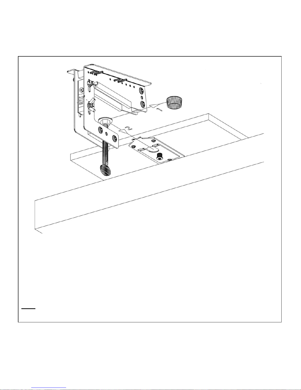
With the mounting plate facing down and hanging over the edge of your workbench,
secure the plywood to your workbench. Remove the clamp pad (1) (it may be stored in
the storage tube) and slide the Route-a-Pocket’s swivel pad between the spring loaded
plates (2). The Route-a-PocketTM will snap securely into position when the swivel pad
finds the large hole in the mounting plate assembly.
Note: The tab on the mounting plate assembly will fit between the Route-a-PocketTM side plates when
properly engaged.
Page 32
Using the Optional Mounting Plate
26
White Oak Tools, LLC
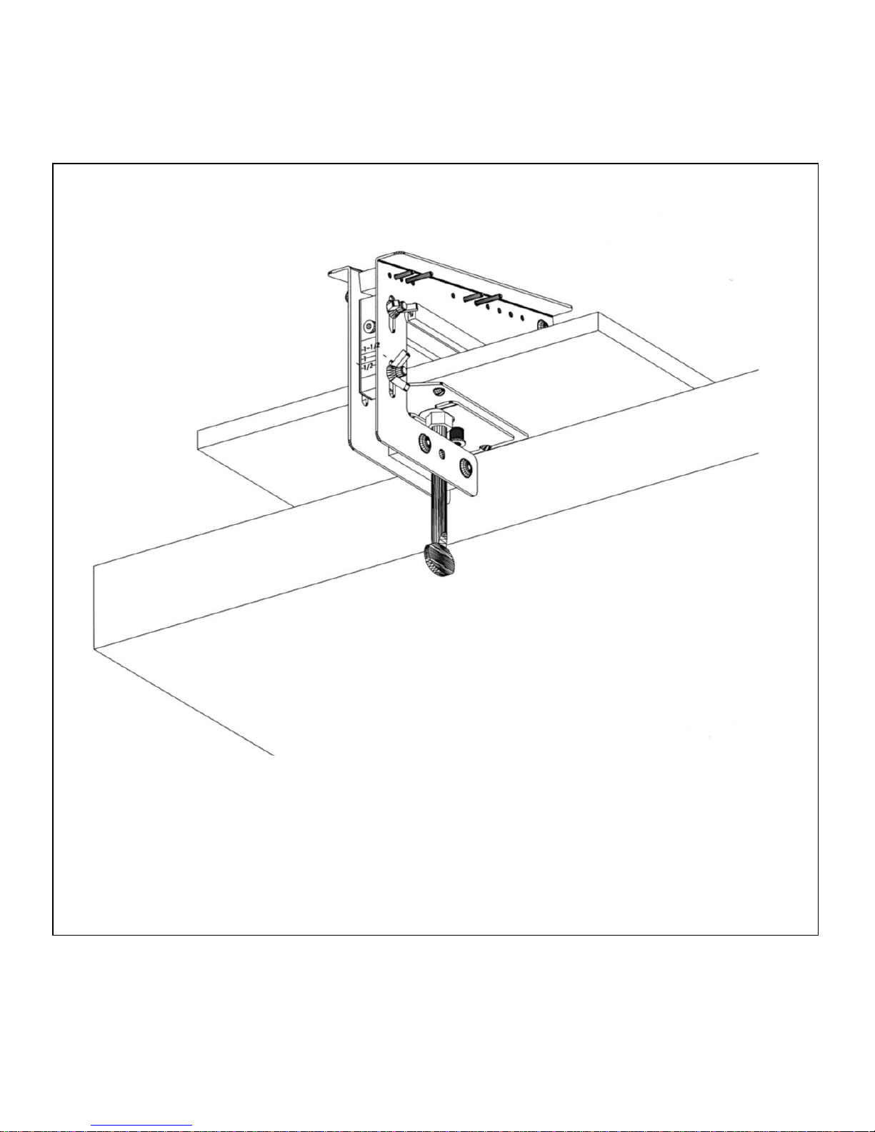
Figure 7c
Route-a-PocketTM shown properly engaged with the mounting plate.
Page 33
Joining Two or More Route-a-Pockets & Maintenance
www.routeapocket.com
27
Figure 8a
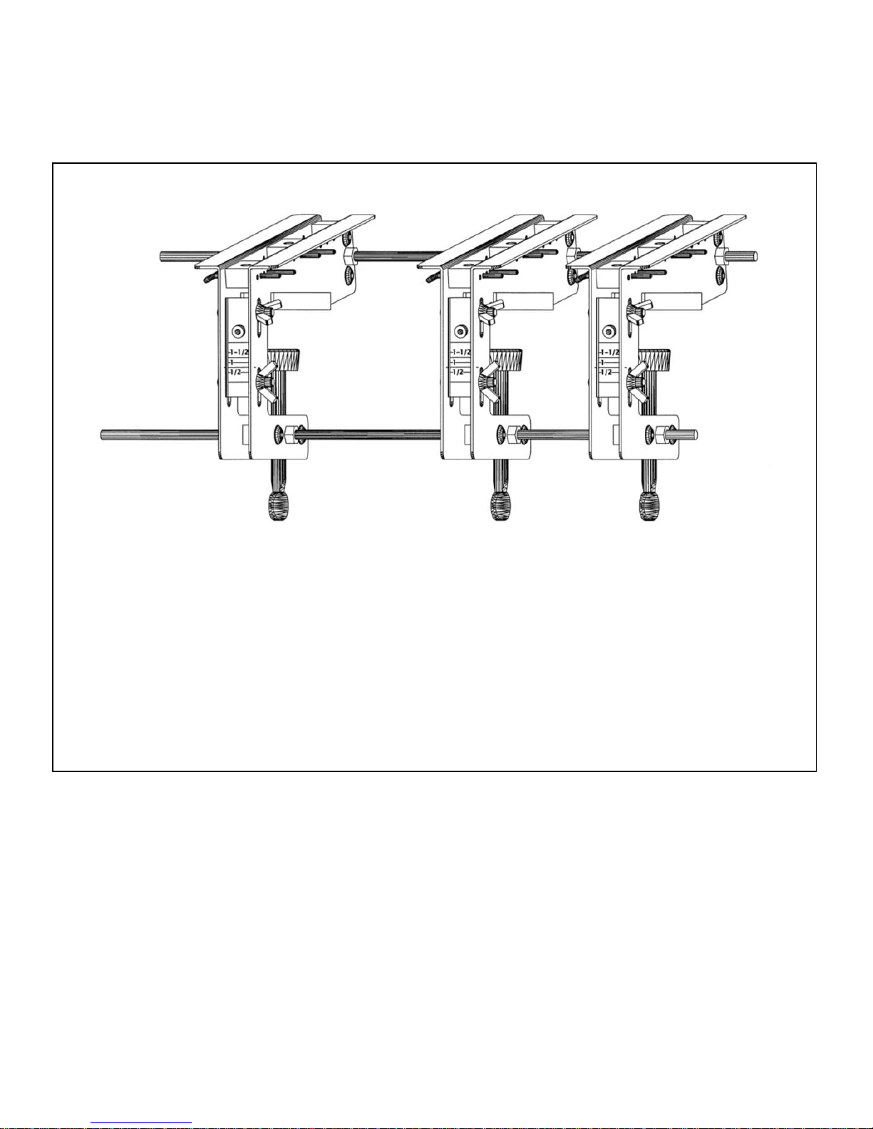
Your Route-a-PocketTM has been designed with two spare through holes. These through
holes may be used to join multiple Route-a-Pockets at fixed distances from each other.
This is often useful when multiple pockets are needed on multiple workpieces.
To join two or more Route-a-Pockets, slide a 1/4” diameter threaded rod (not included)
through each spare hole. Position the Route-a-Pockets along the rods using nuts (not
included) on both sides of each Route-a-PocketTM.
Maintenance
To keep the plunge router sliding smoothly over the incline surface of the Route-aPocketTM, periodically apply a coat of good quality silicone free paste wax to the surface
of the incline.
Page 34

Customer Support
28
Feel free to contact us at:
White Oak Tools
4840 Adams Rd.
Rochester, MI 48306
Email: [email protected]
Website: www.routeapocket.com
Telephone: (248) 891-7198
Additional Route-a-PocketTM components and accessories
can be ordered from our website or by telephone.
Thank you for choosing the Route-a-PocketTM System.
Page 35

This page intentionally left blank.
Page 36

Suggested Route-a-Pocket
TM
Settings
Workpiece
Thickness (in)
#7 Screw
Length
Plunge Depth
& Drill Guide
Height
Lower Stop
Position
Upper Stop
Position
1/2
(note 1)
1
1/2
35B
67D
5/8
1-1/4
5/8
(note 2)
35A
56D
3/4
1-1/2
3/4
35A
56D
1
1-1/2
1
35A
56C
1-1/4
1-1/2
1-1/4
35B
45D
1-1/2
1-1/2
1-1/2
(note 3)
35B
45C
(note 4)
Note 1: Can not be plugged.
Note 2: If plugging, set plunge depth & drill guide height to 3/4”.
Note 3: If plugging, set plunge depth & drill guide height to 1-1/4”.
Note 4: If plugging, set Upper Stop to 45D.
www.whiteoaktools.com
 Loading...