

Page 1
2048 Mercer Road Lexington, Kentucky 40511 • Phone: 859-233-4599 • www.audioauthority.com/aviation
External Power Connector Kit for Experimental Aircraft (PN 670-530)
Installation Example: Van’s Aircraft RV-10
Van’s RV-10 is a very popular Experimental/Amateur-Built (E/AB) aircraft with generous seating for 4 adults
with an aft baggage compartment. The RV-10 primary electrical system components, such as the battery and
master solenoid, are located behind the baggage compartment and the aft bulkhead closeout panel. So, this
example may be instructive for other installations where the battery is in the empennage, such as the RV-8.
This installation example is courtesy of Van’s Aircraft and was performed on their factory demonstrator, N410RV.
Experimental/Amateur-Built (E/A-B) aircraft powered by piston engines are typically not designed or
assembled with a dedicated external power receptacle like those found on most certified aircraft. Those
receptacles are used for high-amperage engine starting and typically bypass the ship’s internal battery.
For E/A-B aircraft, there is the need to energize the airframe for lower amperage tasks such as maintenance,
database updates, flight planning, powered preflight, and the like, but NOT for engine starting. For this
purpose, our Model M1435-EXP Mini-GPU includes a kit of components for the aircraft builder to install a
quick connect harness to the airframe. Installing this DC power connector kit provides a convenient way to
use external ground power and avoid discharging the ship’s battery. The electrical connection is ALWAYS
wired to the battery/master solenoid/contactor, NOT directly to the battery. That connection can be
made to either the input or output side of the contactor, depending on whether the builder intends a
connection for a ground power unit (GPU) or a maintenance type battery charger. See our website or GPU
owner’s manual for wiring diagrams and a full discussion of these tradeoffs.
Page 2
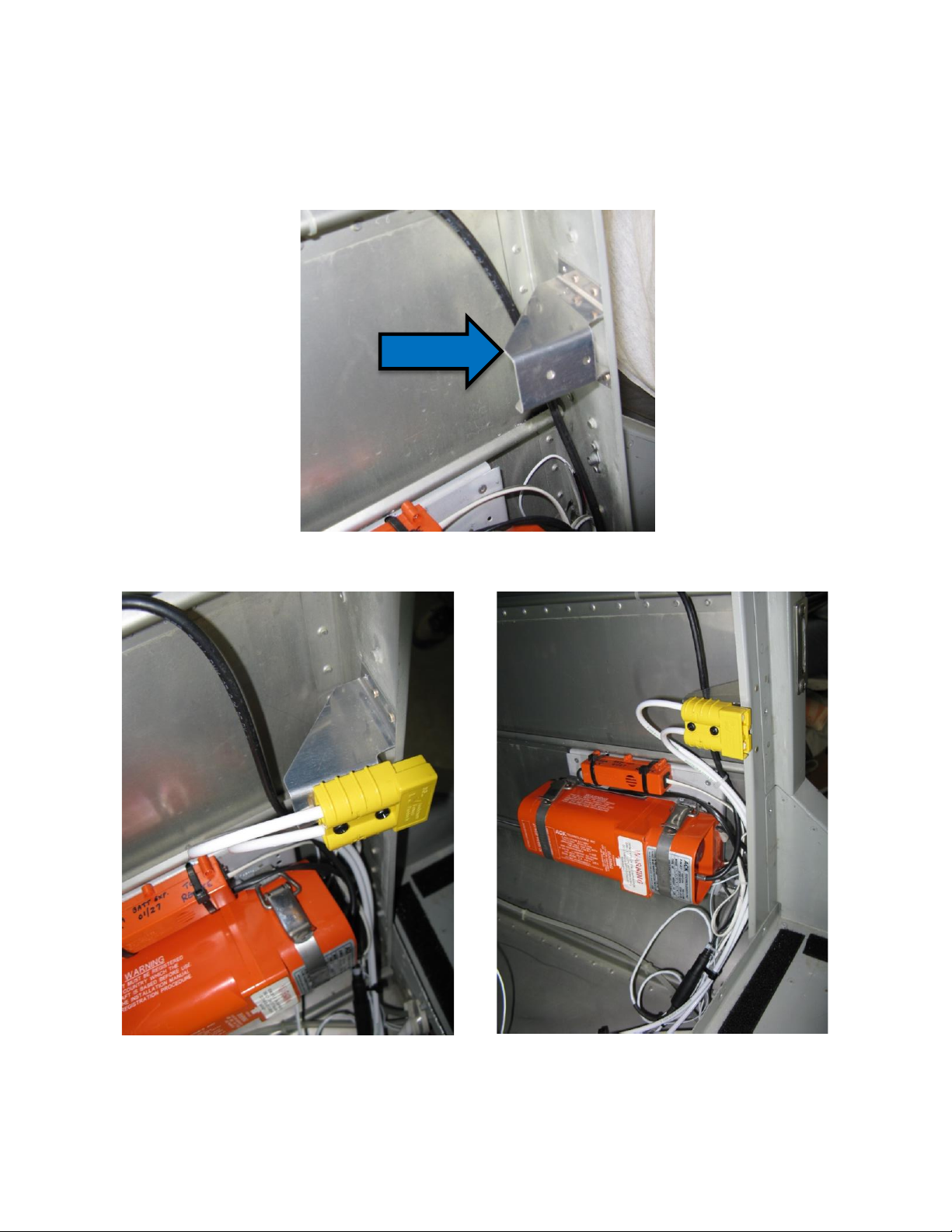
Selecting a location to install the external power receptacle requires proximity to the battery solenoid and
convenient access from outside the aircraft. In this case, the obvious access is through the baggage
compartment door, through the aft bulkhead to reach the battery solenoid or contactor. The installation
scheme is for the SB-50 plug to be mounted to a fabricated bracket (blue arrow) and fastened to the
bulkhead, which positions the plug to be accessed by an opening in the closeout panel.
]
View looking forward at fabricated bracket fastened to bulkhead.
Views of the installed SB-50 plug positioned to access through the baggage closeout panel.
Page 3
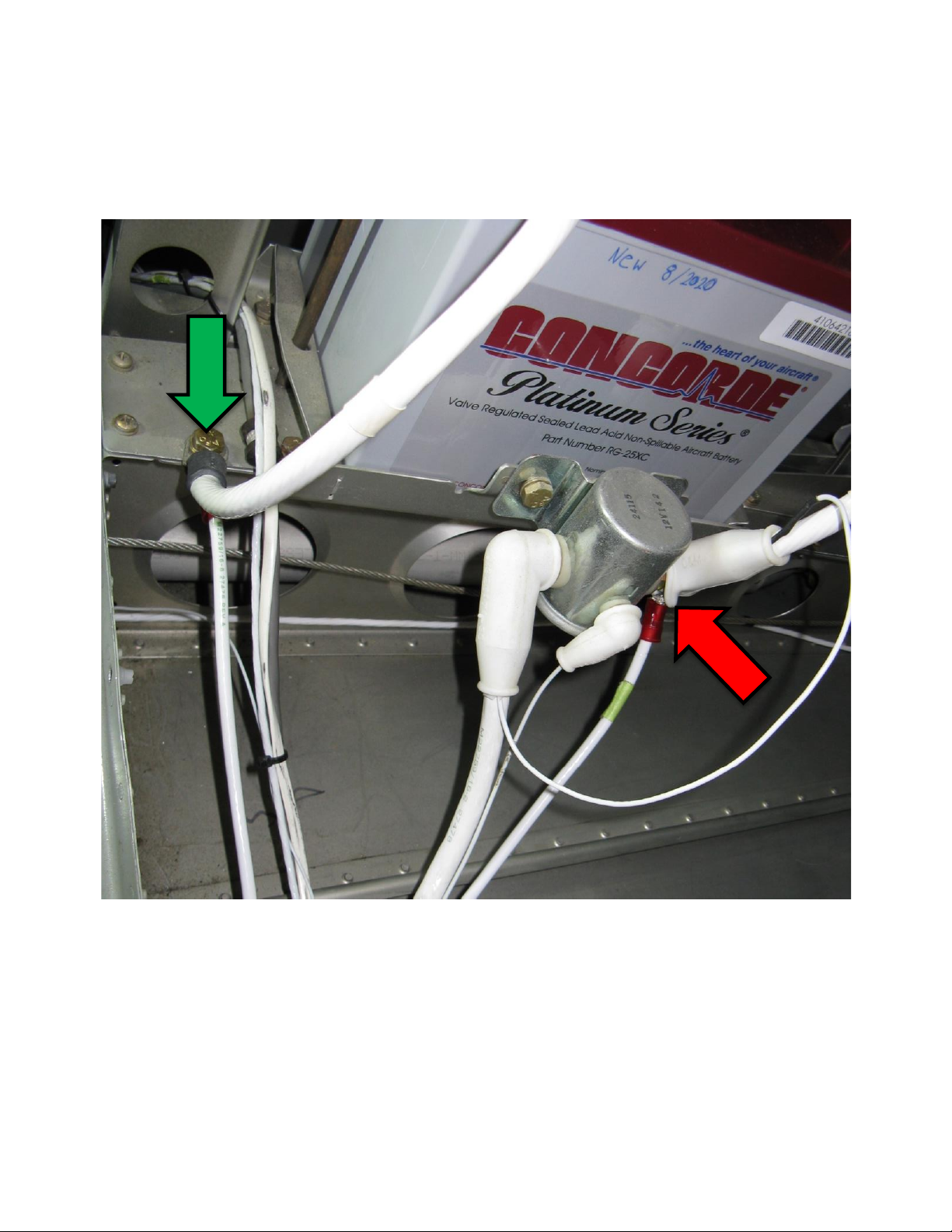
#8 wires for 40-amps maximum run from the external power connector to the area of the battery/master
solenoid/contactor as shown below. #6 wire would allow up to 50A maximum, which is the limitation on this
connector.
In this installation, the positive lead is connected to the input or battery side of the master solenoid (red
arrow). The negative lead is attached under the the bolt used for the battery ground cable (green arrow).
Page 4
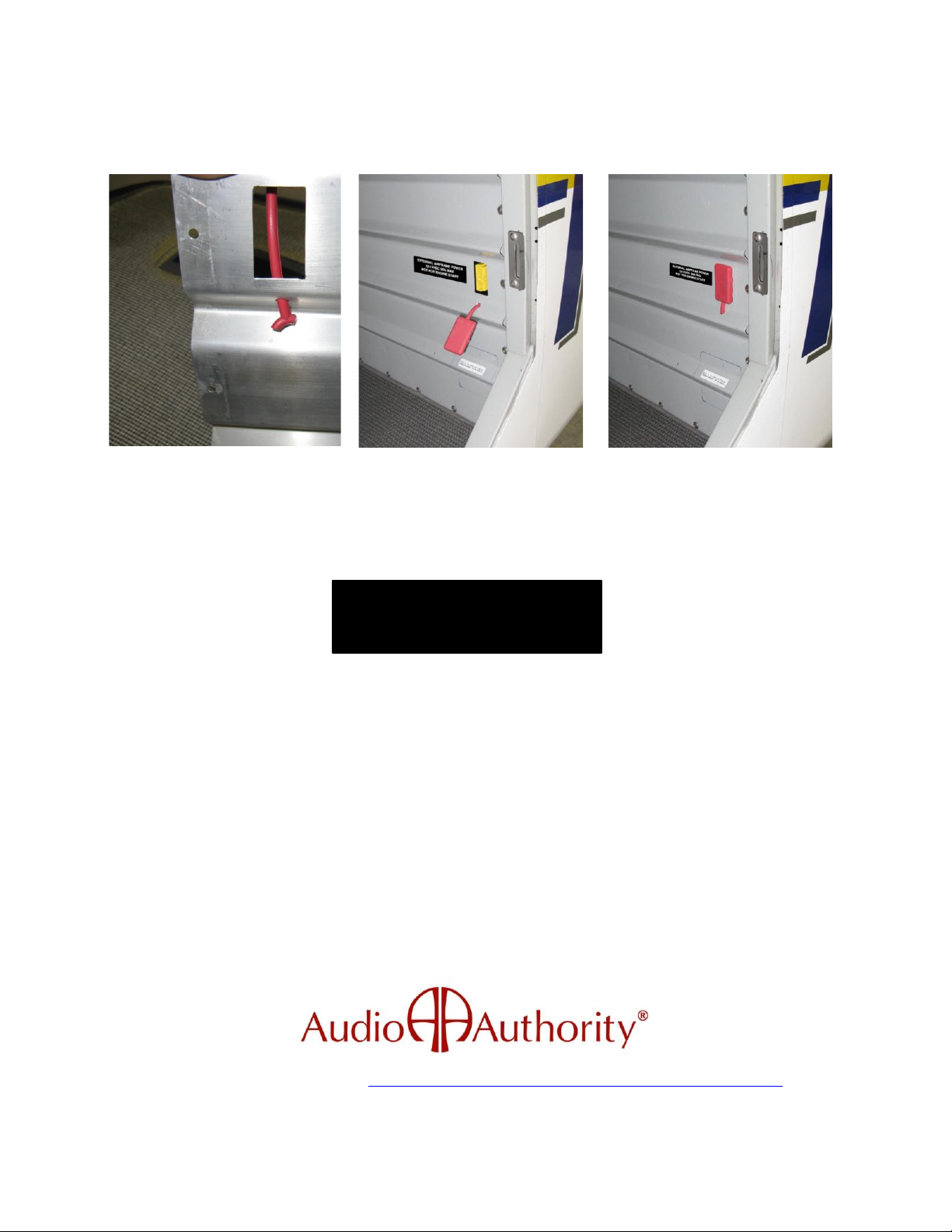
An opening in the baggage closeout panel is cut to allow access to the external power plug. In this case, the
elastomeric dust cover is not fastened to the plug itself but modified to allow it to be attached to the closeout
panel instead.
Opening in baggage closeout panel. Finished installation showing connector exposed and covered. Beautifully done.
Estimated installation time for this procedure is 1-2 hours. When complete, verify continuity and proper
polarity, then functionally test with external power source. Document installation in the airframe maintenance
log and update builder’s POH systems description. Placard the plug to identify its purpose and limitations.
Thanks to the staff at Van’s Aircraft for providing photographs of their installation.
White Lightning™ brand of aviation ground power products are designed and manufactured in the USA by
For more information visit our website: https://www.audioauthority.com/product_details/M1435-EXP
Copyright 2022 Audio Authority Corporation. Lexington, KY USA All rights reserved.
EXTERNAL AIRFRAME POWER
12-14VDC 40A MAX
NOT FOR ENGINE START
 Loading...