

Page 1
© WHITELEY ELECTRONICS LTD. 1998
Filename:G42278final.doc
PETS-2
Crossing Telephone System
Quickfix Installation Guide
Whiteley Electronics Ltd.,
Victoria Street,
Mansfield,
NOTTS. NG18 5RW
TEL: +44 (0) 1623 415600
FAX: +44 (0) 1623 420484
e-mail: [email protected]
AUTHOR: S. RADFORD
DOCUMENT No: G42278
APPROVED BY:
DATE: 13/12/1999
ISSUE:
Professional Light & Sound Association
2
part of the group of companies
Page 2
Page 2 of 40
Issue 2
13/12/99
PETS-2 Crossing Telephone System
QUICKFIX INSTALLATION HANDBOOK
2
WARNINGS
HAZARDOUS VOLTAGES
PETS 2 is to be powered from a telecommunications quality dc supply, nominally 24V dc or
50V dc (subject to internal configuration). The 50V dc supply must be treated as a hazard
as it exceeds the levels specified within the ‘Low Voltage Directive’.
Furthermore, whilst 24V dc supplies are considered to be ‘ELV’, PETS 2
incorporates a dc-dc converter that produces a 60V dc level, and can
additionally generate telephone ringing voltages in the order 120V peak to
peak. The circuits within PETS 2 must be treated as hazardous under all
circumstances, and the power supply (mains and battery) should be isolated before removal
of equipment covers.
PROTECTIVE EARTH
The PETS 2 equipment must be earthed, but care must be taken to use a ‘local’ earth for
safety reasons. In most instances the equipment case will be bonded to
‘Telecommunications earth’ by connecting the ‘green/yellow’ lead from a tag
on the outside of the case to the earth point within the Junction Box’. The
earth point within the Junction Box will be bonded to an existing
‘Telecommunication earth’, or to a dedicated ground spike. In some
instances the equipment may be fixed to a signallin g frame , where the case
will be bonded by connection of the ‘green/yellow’ wire to the appropriate earth of the
signalling equipment. Under these circumstances the ‘Telecommunications Earth’ within the
Junction Box, and the earth reference to the power supply/ electronics will be kept isolated
from the signalling earth.
CAUTIONS
INSTALLATION INSTRUCTIONS
This handbook is supplied with the Signal Box and Crossing PETS 2 equipment, there are
minor differences between these two items and it is important to identify
each item before starting the installation. This handbook is intended to
cover the installation process only. A competent design authority must
undertake a survey of the installation, and shall then provide additional
installation instructions relating to the specific configuration, wiring
arrangement and location of equipment. A separate PETS 2 ‘Handbook for Design,
Installation and Maintenance’ (WEL part G42279) is available for use by competent
designers and maintainers.
TELECOMMUNICATIONS SAFETY
PETS 2 has isolated barriers to BS6301 on each circuit for connection to a
transmission system, or to a physical circuit between the Signalbox and
Page 3
PETS-2 Crossing Telephone System
QUICKFIX INSTALLATION HANDBOOK
Page 3 of 40
Issue 2
13/12/99
3
remote location. Within the Junction Box, Block 3 is dedicated to these isolated circuits. The
25 way ‘D’ connector and its 10 pair cable are also dedicated to these isolated circuits. DO
NOT make connections between Block 3 circuits and other circuits of the PETS 2 system.
The Telecommunications safety earth is relevant to the local PETS 2 Telecommunication
circuits (Crossing Telephones), the PETS 2 power supplies and electronics. The ‘isolated’
circuits to remote sites via physical circuits or transmission equipment are always isolated
from the local earth (this is to ensure that ground potential differences do not cause
circulating currents)
WIRING
Telephone circuits carry low level signals, of a few hundred milli-volts. These
circuits are particularly susceptible to external electro-magnetic influences. It
is always advisable to avoid routing these cables near to power cables or
other potential interference sources. Provision is made within the Junction
Box for earthing of the cables, do so at the Junction Box end only. Ensure
there is a low impedance path to earth from the Telecommunications Earth
within the Junction Box.
LIGHTNING
A risk of lightning damage exists if the cables are external to a building, and/or the physical
circuit is overhead. If the risk of lightning strike is low then QDF protection
magazines should be fitted within the Junction Box, on the circuits at risk. If
the risk is high (cables conveyed overhead, or track-side) then separate
lightning protection should be installed, using a separate protection unit and
a dedicated earth point.
STATIC SENSITIVE PRECAUTIONS
PETS 2 plug in modules use components that are static sensitive. When
removing/ fitting plug in cards ensure that an anti-static wrist strap is worn.
The strap should be connected to the earth stud provided and marked with
the ‘Static Sensitive Handling’ label.
Page 4

Page 4 of 40
Issue 2
13/12/99
PETS-2 Crossing Telephone System
QUICKFIX INSTALLATION HANDBOOK
4
CONTENTS
1. INTRODUCTION 7
2. EQUIPMENT SUPPLIED 7
2.1 Signal Box Kit (WEL part A35154) 7
2.2 Level Crossing Kit (WEL part A35155) 8
3. ACCESSORIES 8
4. OUTLINE DESCRIPTION 9
4.1 PETS 2 - Enhancements 10
4.2 Signal Box Unit 11
4.2.1 Item 1 - Connection Plate 11
4.2.2 Item 2 - Connector Retention bracket 12
4.2.3 Item 3 - Frame retention bolts 12
4.2.4 Item 4 - Right hand access plate 12
4.2.5 Item 5 - Front panel 12
4.3 Level Crossing Unit 13
4.3.1 Item 1 - Connection Plate 14
4.3.2 Item 2 - Connector Retention bracket 14
4.3.3 Item 3 - Frame retention bolts 14
4.3.4 Item 4 - Right hand access plate 15
4.3.5 Item 5 - Front panel 15
4.4 Inside the case 15
4.4.1 Item 6 - Transmission Card (A33837) 16
4.4.2 Item 7 - Line cards (A33838 - Level Crossing), (A35173 - Signalbox) 16
4.4.3 Item 8 - CPU card (A33839 - Level Crossing), (A35176 - Signalbox) 16
4.4.4 Item 9 - Power Supply & Ringer Card (A33898) 16
4.4.5 Item 10 - Fuseholder +12V (fused) 16
4.4.6 Item 11 - Earth stud for wrist strap 16
4.4.7 Item 12 - Card Pullers 16
4.4.8 Item 13 - Voltage selection link (refer to section 5.8.1) 17
5. INSTALLATION 19
5.1 Installation tools 19
5.2 Unpacking the equipment 19
5.3 Preparation 19
Page 5

PETS-2 Crossing Telephone System
QUICKFIX INSTALLATION HANDBOOK
Page 5 of 40
Issue 2
13/12/99
5
5.4 Wall fixing 19
5.5 Safety Earth 22
5.6 Configuration 23
5.6.1 Signal Box Unit 24
5.6.2 Level crossing Unit 24
5.7 Front panels 25
5.7.1 Signalbox front panel 25
5.7.2 Level Crossing Unit front panel 26
5.8 Wiring 27
5.8.1 Power supply 30
5.8.2 Local telephone wiring (Level Crossing) 32
5.8.3 Transmission Circuits 33
5.8.4 Miscellaneous Wiring 34
6. TECHNICAL DATA 35
6.1 Mechanical details 35
6.2 Electrical 35
6.3 Telephony 35
6.3.1 Telephone Circuits 35
6.3.2 Transmission 35
6.4 Environmental 36
Page 6

Page 6 of 40
Issue 2
13/12/99
PETS-2 Crossing Telephone System
QUICKFIX INSTALLATION HANDBOOK
6
LIST OF FIGURES
FIGURE 1 - PHOTOGRAPH OF SIGNALBOX UNIT 11
FIGURE 2 - PHOTOGRAPH OF LEVEL CROSSING UNIT 13
FIGURE 3 - PHOTOGRAPH OF THE CARD FRAME 15
FIGURE 4 - CARD REMOVAL TECHNIQUE 17
FIGURE 5 - SIGNALBOX UNIT SHOWING LABEL INSERTS 25
FIGURE 6 - LEVEL CROSSING UNIT (FRONT PANEL EARTH TAG) 26
FIGURE 7 - INTERNAL LAYOUT - JUNCT ION BOX 27
FIGURE 8 - POWER SUPPLY VOLTAGE SELECTOR (APPLICABLE TO SB & LC UNITS)31
Page 7

PETS-2 Crossing Telephone System
QUICKFIX INSTALLATION HANDBOOK
Page 7 of 40
Issue 2
13/12/99
7
1. INTRODUCTION
This handbook is provided to enable the basic installation of PETS 2 Signal Box and PETS
2 Crossing equipment. Basic installation covers the standard installation format - a single
Signalbox unit connected to a single Level Crossing unit. A competent design authority
must undertake a survey of the site prior to installation, and shall then provide any
additional installation instructions relating to the specific configuration, wiring arrangement
and location of equipment. A separate PETS 2 ‘Handbook for Design, Installation and
Maintenance’ (WEL part G42279) is available for use by competent designers and
maintainers.
This equipment conforms to an updated design, and most installers may be familiar with the
original PETS equipment. The most significant differences between PETS (original) and
PETS 2 are listed, as follows:
• External appearance - new colour and styling of front panels
• Front panels use labels, and buttons on the Signal Box unit use the label as a
‘membrane’ cover.
• External connections are now made through QDF IDC connectors within an external
junction box. Connections from the PETS 2 equipment are made through ‘D’ connectors
to 2 metre connecting leads, terminated on the QDF blocks.
• Power supply design accepts higher voltage transient levels and the unit includes EMC
filtering.
• Card extractors included and stowed within.
• Card frame removal from case improved.
• Case to wall fixing improved by rear ‘bumps’.
• Integration of power supply/ battery charger alarms
• Minor software changes.
• Equipment Alarm 7 segment display and ‘Interrogate’ button of the Signal Box unit may
be replaced by a remote display unit.
2. EQUIPMENT SUPPLIED
The Signal Box unit may be recognised by the four ‘CALL’ buttons on its front panel, red in
colour. The Level crossing unit may be distinguished by the large number of LED apertures
on its front panel. There are two line cards supplied with the Level Crossing unit, whereas
Signal Box units are supplied with one line card only.
The Junction box supplied with the Signal Box unit includes a pre-wired alarm sounder.
2.1 Signal Box Kit (WEL part A35154)
Upon opening the packaging, the contents should be checked to the following list:
Page 8
Page 8 of 40
Issue 2
13/12/99
PETS-2 Crossing Telephone System
QUICKFIX INSTALLATION HANDBOOK
8
1 off PETS 2 Signal Box unit, with card removal ‘pullers’ (inside)
1 off Junction Box, complete with pre-wired connectorised leads.
1 off Installation Handbook (this book)
1 off 9 pin female ‘D’ connector (for the power supply lead)
1 off Earth lead - M6 ring terminal and 2 metre green/ yellow wire
2.2 Level Crossing Kit (WEL part A35155)
Upon opening the packaging, the contents should be checked to the following list:
1 off PETS 2 Level Crossing unit, with card removal ‘pullers’ (inside)
1 off Junction Box, complete with pre-wired connectorised leads.
1 off Installation Handbook (this book)
1 off 9 pin female ‘D’ connector (for the power supply lead)
1 off Earth lead - M6 ring terminal and 2 metre green/ yellow wire
3. ACCESSORIES
The following table provides information on the standard accessories available for use with
PETS 2:
WEL Part No. Signal Box Crossing Description
A33838 Note 2 Line Card - for local telephones. This Line card
is identical to the original PETS Line card; and
is also used on PETS 2 but within the Level
Crossing unit only.
A35173 Note 1 Line Card - Signalbox PETS2. This item is
different to the original due to a modified CALL
button arrangement.
A34566 (new
version from Q3
’98 - A35168)
Note 3 Note 3 Power supply and battery charger, batteries
not included.
A35166 Note 4 NA Remote Alarm Display Kit
A35169 Note 5 Note 5 Battery Set (4 off) 6Ahr
A35170 Note 5 Note 5 Battery Set (4 off) 12Ahr
A35171 Note 6 Note 6 Battery Set (4 off) 17Ahr
A35172 Note 7 Note 7 Firmware Upgrade (when applicable)
G42279 Note 8 Note 8 ‘Handbook for Design, Installation and
Maintenance’
G42279CD Note 8 Note 8 CD version of ‘Handbook for Design,
Page 9
PETS-2 Crossing Telephone System
QUICKFIX INSTALLATION HANDBOOK
Page 9 of 40
Issue 2
13/12/99
9
WEL Part No. Signal Box Crossing Description
Installation and Maintenance’
Note 1 : The Signal Box unit is supplied with one Line Card. Additional line cards may be
required in the Signal Box Unit when working in Paired mode.
Note 2 : The Level crossing unit is supplied with two line cards; additional cards will be
required for paired mode or when four telephones have to be provided at a particular
crossing.
Note 3 : This is a wall mounted power supply and charger with integral shelves for the
batteries. The size of battery, and the number of PETS 2 units attached to each charger will
be determined by system design for the appropriate backup period. From Q3 1998 an
upgraded version of the charger will be available, providing enhanced monitoring and
integration with the PETS 2 equipment. The original Power Supply and Charger can be
used to power PETS 2.
Note 4 : The Remote Alarm Display Kit may be fitted at the Signalbox end and comprises a
small plastic enclosure with a seven segment display and ‘Interrogate’ button. This small
enclosure is to be fixed onto a wall or concentrator. The kit includes a ribbon connector
assembly, to be installed between the internal CPU and termination cards. Also supplied is
a 15 metre lead wired to the Remote Alarm Display. The other end of the cable is to be
terminated in the PETS 2 Junction Box.
Note 5 : Battery sets of 6Ahr or 12Ahr for use with the original and new version Power
Supply and Battery Charger.
Note 6 : The 17Ahr battery option is available with the new Power Supply and Battery
Charger, only.
Note 7 : Please check with WEL Sales Office before ordering. When firmware upgrades
are available, this code number relates to a single EPROM - the same EPROM is used
within the Signal Box and the Level Crossing units.
Note 8 : This handbook is intended for System Designers and Maintainers and covers a
wide range of topics not covered by this handbook. The document is available ring bound or
on CD in Adobe Acrobat .PDF format.
4. OUTLINE DESCRIPTION
This is not a detailed description of the PETS 2 equipment, merely an outline account
aimed at describing the f eatures relevant to installa tion. Installers who a re familiar with th e
original PETS equipment should read section 4.1 carefully.
Page 10

Page 10 of 40
Issue 2
13/12/99
PETS-2 Crossing Telephone System
QUICKFIX INSTALLATION HANDBOOK
10
The design of PETS 2 equipment is almost identical at the Signal Box and Level Crossing
ends. The major difference is the front panel arrangement. The Level Crossing Unit has a
metal front panel with formed edges fitting over the case. A label covers all of the front
panel apertures, and the arrangement (in conjunction with an internal rubber seal) ensures
that the case is sealed to IP55. The Signal Box unit has a front panel fitting to the internal
case edges. The front panel is a label membrane laminated to an aluminium back plate.
The Signal Box unit is not sealed to IP55; and other sealing arrangements, normally
associated with the Level crossing Unit, are omitted.
4.1 PETS 2 - Enhancements
The following list of bullet points should be noted by readers already familiar with the
installation of the original PETS equipment:
• Cable terminations are no longer to terminal blocks within. All terminations are available
through connectors on the side of PETS 2. A separate Junction Box complete with prewired leads is supplied; QDF IDC connectors are used throughout.
• The equipment case has improved wall fixing, with ‘bumps’ to allow for irregular wall
surfaces and to recess the fixing screw head.
• The Euroframe is easier to remove from the case.
• The auxiliary 12V dc supply is now independently fused.
• Card pullers are provided with each unit and are stowed behind the front panel.
• A stud for an ‘Anti-static wrist strap’ is now provided behind each front panel.
• The firmware has been revised to incorporate some improvements and some new
features.
• Barrier signalling on Line 1 has been re-allocated to bi-directional signalling of a mains/
charger fail alarm.
• Barrier Signalling Inputs and Outputs are no longer ‘volt free’. To simplify the wiring these
circuits are referenced to the secondary supply (+12V & 0V) of PETS 2.
• Front panels have been totally re-styled
• Earthing and EMC arrangements have been improved.
• Power supply has upgraded components allowing operation with higher input voltage
surges and transients.
• CPU card has been modified to allow remote seven segment display and maintain the
display within the Signal Box Unit.
• Front panel master alarms (previously referenced as Alarm 1 & Alarm 2) are now termed
Minor and Major. Positions on the front panel have been transposed.
• Firmware is different between new and old PETS equipment; but original PETS firmware
is also available with the new features.
Page 11
PETS-2 Crossing Telephone System
QUICKFIX INSTALLATION HANDBOOK
Page 11 of 40
Issue 2
13/12/99
11
4.2 Signal Box Unit
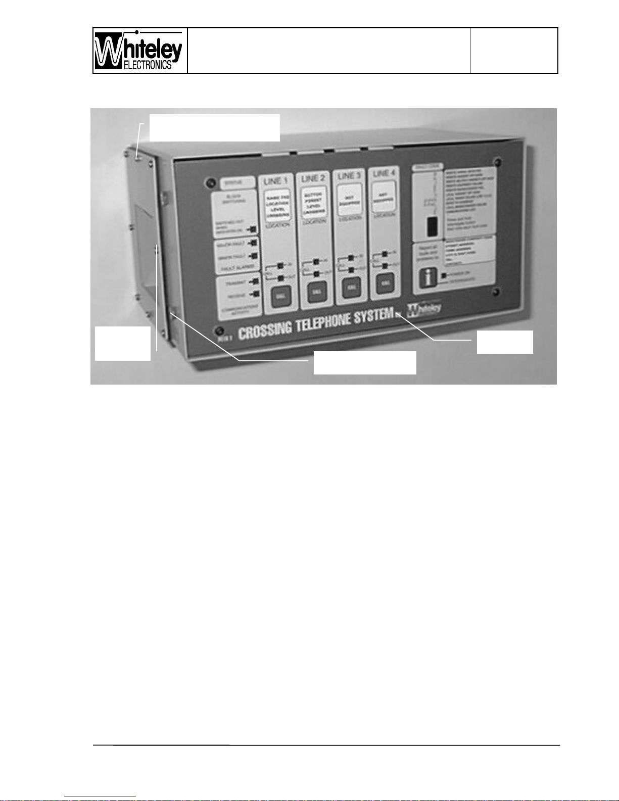
Figure 1 - Photograph of Signalbox Unit
The Signal Box unit is designed for wall mounting, although it may sometimes be adapted
for rack mounting. The casing of Signal Box and Level Crossing units are identical, but the
front panel arrangements are entirely different.
On the Signal Box units, the front panel comprises a membrane / label front laminated onto
a 4mm aluminium plate. This is fitted ‘inside’ the case edges, allowing the panel to be
recessed more than the Level crossing arrangement. This recessing enables the buttons
(on the cards within) to be activated through the front membrane. This presents a smooth,
wipe clean front panel, with the advantage of having ‘real’ push buttons. Unused button
locations are protected by a supporting disk behind the membrane, at each unused location
(Lines 2,3 & 4 on a standard Signal Box Unit).
4.2.1 Item 1 - Connection Plate
Shown in the photograph (Fig. 1) without connectors and Connector Retention bracket. All
of the connections to PETS are made through plug/ socket ‘D’ type connectors to the left
hand side of the unit. On the Signal Box unit, these connectors are not environmentally
sealed. However, the connector arrangements are novel as their right angle shells are used
Item 3
Fr
ame Retention bolt
Item 5
Fr
ont pane
l
Item 1
Connection
Connector retention
bracket, upper fixing screw.
Page 12

Page 12 of 40
Issue 2
13/12/99
PETS-2 Crossing Telephone System
QUICKFIX INSTALLATION HANDBOOK
12
to direct the cables to the wall. Right angle connector cannot use the more conventional
screw lock arrangement, and these connectors (all three) are retained in place by means of
a Connector Retention bracket. The connectors have the following functions:
1. 9 pin ‘D’ connector - power supply input and mains/charger alarm.
2. 25 pin ‘D’ connector - isolated telecommunications interfaces, i.e. transmission circuits.
3. 50 pin ‘D’ connector - all other PETS circuits, e.g. crossing telephones, etc.
Connectors 2 & 3 above are pre-wired to a Junction Box.
4.2.2 Item 2 - Connector Retention bracket
The photograph (Fig. 1) does not show this bracket. This bracket fits onto the Connector
Plate using the middle two screws, the upper screw is identified in the photograph. This
retention bracket has a series of forms to apply pressure at the rear of each ‘D’ connector
shell. As the bracket is fixed into position, by tightening the two fixing screws, the ‘D’
connectors become locked and fully mated.
4.2.3 Item 3 - Frame retention bolts
Shown in the photograph (Fig. 1) are the two left side retention bolts. The entire inner card
frame is removable from the outer casing. The two M6 hexagonal bolt heads at each side
secure the frame within the case. These bolts must not be removed unless the procedure
described in section 5.4 is followed.
4.2.4 Item 4 - Right hand access plate
The right hand access plate is equipped with a series of 20mm knockouts. This plate is not
usually required for standard installations. It has been retained in PETS 2 to allow access to
the right hand side of the frame and the motherboard. The right hand side of the case, and
this plate, cannot be seen in the photograph (Fig. 1)
4.2.5 Item 5 - Front panel
The front panel has a polyester membrane laminated onto an aluminium backing plate. This
Polyester membrane also serves as a label to identify the functions of the PETS 2 Signal
Box Unit. The front panel is secured to the internal card frame by means of the four button
head Allen Key M4 screws at the front. The following aspects of the front panel are of
particular note:
a) CALL buttons - The Signal Box Unit is equipped with a single Line Card, as standard.
The remaining CALL buttons allocated to Lines 2,3 & 4 have a blanking plug fitted to the
inside of the front panel, thereby preventing movement of the Polyester membrane in the
unused locations. The blanking plug will be removed in case of installing additional line
cards.
Page 13
PETS-2 Crossing Telephone System
QUICKFIX INSTALLATION HANDBOOK
Page 13 of 40
Issue 2
13/12/99
13
b) Line Identification window - Each Crossing will be geographically identified by a label to
be inserted from the top edge of the front panel, between the front Polyester membrane
and the aluminium panel. When the front panel is fitted it is not possible to access the
opening for this label, hence the label is securely located after installation. The black
PVC tape to the rear of the front panel is to prevent the LED’s behind from showing
through the paper insert labels. This is particularly relevant to Line 1, to prevent
illumination if a mains/ charger alarm occurs. W hen ‘Barrier Alarm signalling’ is required
on Line Cards 2, 3 or 4; puncture a hole in the PVC tape to selectively allow operation of
the required LED’s. In the photgraph the paper label inserts can be seen behind each
window.
c) Service Provider Identification window - an additional window is provided, with access
from the right hand edge of the front panel. This window will be used to identify the
Service Provider and fault notification telephone number.
Front panel layout is broken into functional sections, and the Fault Codes are identified with
a brief explanation to allow the Signaller to give a detailed indication of the fault status when
reporting problems. The INTERROGATE (a large lower case ‘i’ legend) button allows the
unit to be interrogated and the seven segment display to cycle through each alarm in the
event of multiple alarms. Other LED indicators are visible through the front panel, allowing
the general status of PETS 2 to be visible.
4.3 Level Crossing Unit
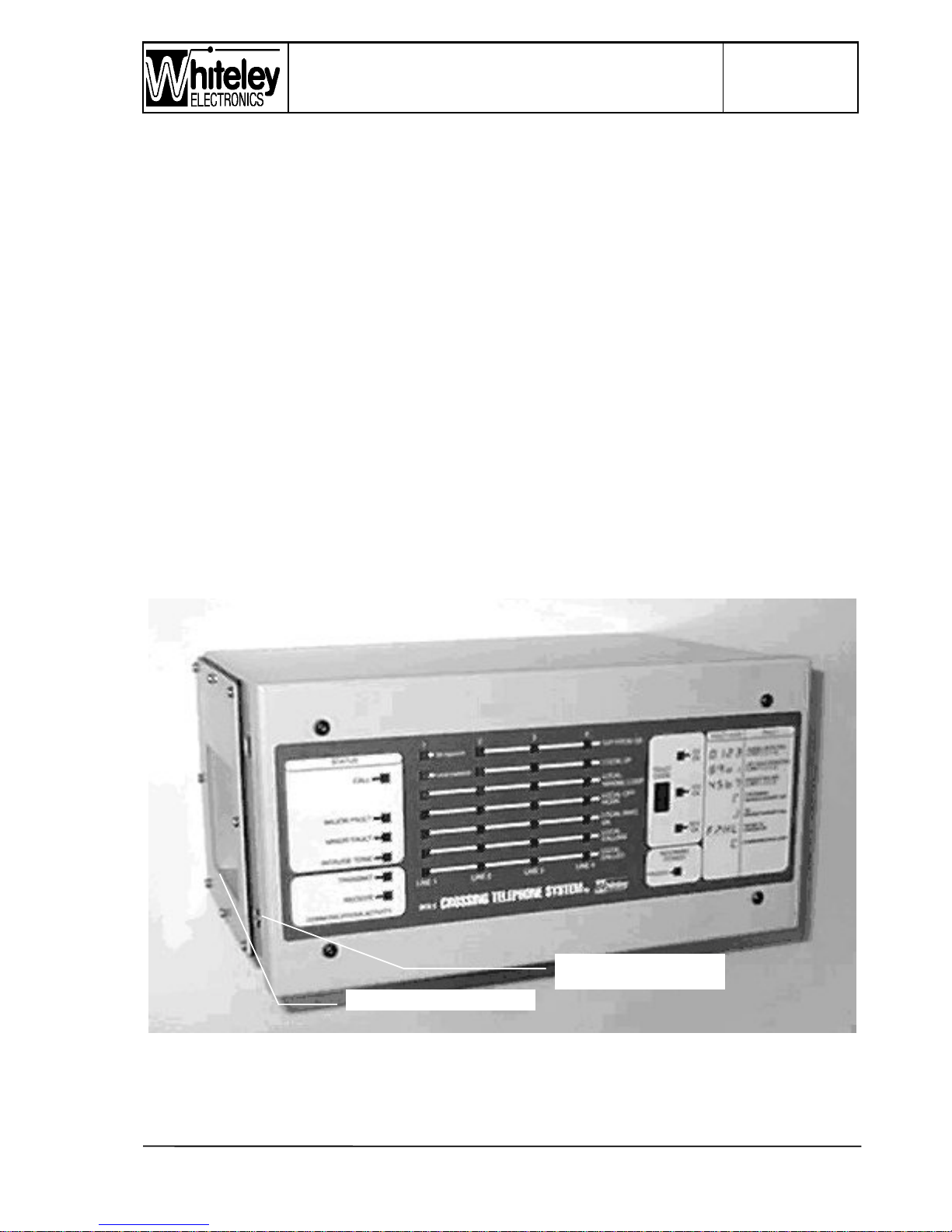
Figure 2 - Photograph of Level Crossing Unit
Item 3 - Frame retention
bolt & case earth point
Item 1 - Connection Plate
Page 14

Page 14 of 40
Issue 2
13/12/99
PETS-2 Crossing Telephone System
QUICKFIX INSTALLATION HANDBOOK
14
The Level Crossing Unit outer case is identical to that of the Signal Box unit. The case was
originally intended to be compatible with the space taken by two BR Signalling Relays,
although normal practise is to install the unit within an equipment room. PETS 2 retains the
environment capability to be installed into a signalling or telecommunications track-side
location cabinet. The Level Crossing Unit is sealed to IP55, and internal PCB’s (of both
units) are conformally coated for added environmental protection. The front panel
arrangement of the Level Crossing Unit is entirely different to that of the Signal Box Unit.
The Level Crossing Unit has no front panel operated buttons, and the panel is placed
further forward to allow dust & water seal to be made between the front panel and the case.
All of the internal indicators are visible through a label fitted to the front panel. Other
features are detailed below:
4.3.1 Item 1 - Connection Plate
This is identified at the left side of the photograph (Fig.2). The arrangement of connectors is
identical to that of the Signal Box, please refer to 4.2.1. However, the following important
differences should be noted:
a) A foam rubber seal is provided around the ‘D’ connectors of the Level crossing Unit to
maintain the IP55 seal
b) The Junction box of the Level Crossing Unit is different to that of the Signal Box, for
instance there is no alarm sounder in the Level Crossing Unit Junction Box.
NOTE: It is recommended that Silica Gel bags are inserted in the Level Crossing Unit case
and inside the Junction Box as a precaution against the effects of condensation.
4.3.2 Item 2 - Connector Retention bracket
The Connector rention bracket is not shown in this photograph (Fig. 2), but it is visible in Fig
5. The bracket fits onto the Connector Plate using the middle two screws. This retention
bracket has a series of forms to apply pressure at the rear of each ‘D’ connector shell. As
the bracket is fixed into position, by tightening the two fixing screws, the ‘D’ connectors
become locked and fully mated.
4.3.3 Item 3 - Frame retention bolts
Two of the rention bolts can be seen on the left side, the lower bolt is identified on the
photograph (Fig. 2), and this has a special significance as the main earth point for the case.
The entire inner card frame is removable from the outer casing. The two M6 hexagonal bolt
heads at each side secure the frame within the case. These bolts must not be removed
unless following the procedure described in section 5.4
Page 15
PETS-2 Crossing Telephone System
QUICKFIX INSTALLATION HANDBOOK
Page 15 of 40
Issue 2
13/12/99
15
4.3.4 Item 4 - Right hand access plate
Photograph (Fig. 2) does not show the right hand side of the case, consequently Item 4 is
not identified. The right hand access plate is equipped with a series of 20mm knockouts.
This plate is not usually required for standard installations. It has been retained in PETS 2
to allow access to the right hand side of the frame and the motherboard.
4.3.5 Item 5 - Front panel
On the Level Crossing Unit the front panel takes the form of a metal tray with turned up
edges. Around the inside edge a strip of foam rubber sealing material is fitted, when the
front panel is fitted the seal is compressed by the edge of the case.
The front panel label allows all of the LED’s within to be visible, including the seven
segment Fault Code display. It is necessary to remove the front panel, by means of the four
fixing screws, to access the ‘Interrogate’ button to review multiple alarms. Removal of the
front panel will reveal the RESET button (immediately beneath the seven segment display).
The Interrogate button is beneath the RESET button.
4.4 Inside the case
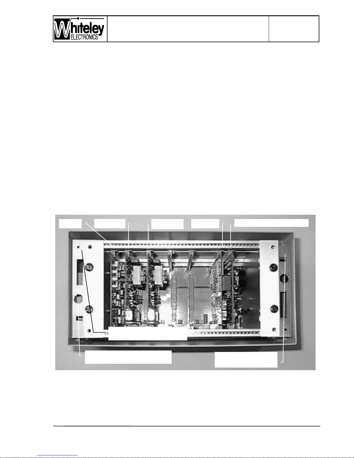
Figure 3 - Photograph of the Card frame
Item 11
Stud for anti-static
wrist str
ap
Item 10
F
use
- 100mA for +12V external
Item 12
Card puller stowage
TX card Line card 1 Line card 2 CPU card Power supply & ringer card
Page 16

Page 16 of 40
Issue 2
13/12/99
PETS-2 Crossing Telephone System
QUICKFIX INSTALLATION HANDBOOK
16
4.4.1 Item 6 - Transmission Card (A33837)
There is a single Transmission Card in each frame, located to the left hand side. The card
is identical at Signalbox and at the Level Crossing.
4.4.2 Item 7 - Line cards (A33838 - Level Crossing), (A35173 - Signalbox)
In the Signalbox unit a single line card is provided in the Line 1 position. The card is
electrically identical to those of the Level Crossing, the only difference being the button
arrangement for use with the membrane overlay.
In the Level Crossing units, Line1 and Line 2 cards are fitted.
4.4.3 Item 8 - CPU card (A33839 - Level Crossing), (A35176 - Signalbox)
The Signalbox card is electrically identical to those of the Level Crossing, the only
difference being the button arrangement for use with the membrane overlay. This card
houses the seven segment display and the system firmware. The same version of firmware
can be used throughout. DIL switches on the motherboard distinguish the Signalbox and
Level Crossing units, additionally establishing whether the hardware is original PETS or
PETS 2.
4.4.4 Item 9 - Power Supply & Ringer Card (A33898)
There is a single Power Supply & Ringer Card in each frame, located to the right hand side.
The card is identical at Signalbox and at the Level Crossing.
4.4.5 Item 10 - Fuseholder +12V (fused)
Located to the left hand side this fuse protects the external +12V from the frame.
4.4.6 Item 11 - Earth stud for wrist strap
Connection point for wrist straps
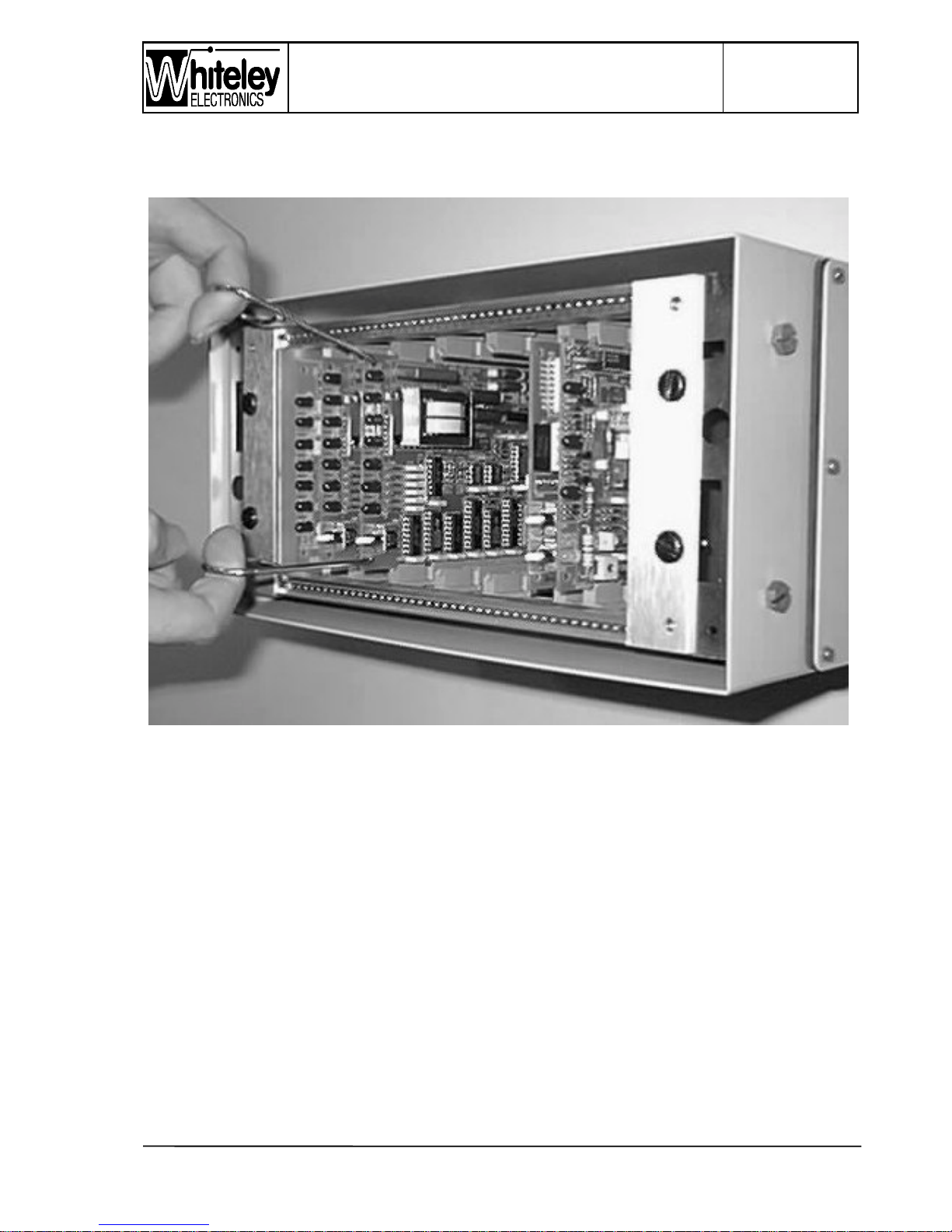
4.4.7 Item 12 - Card Pullers
A pair of card pullers are located to the right hand side. This is a convenient stowage
location. The large ring is to be pulled by the fore-finger of each hand. The bent end of each
puller is located in the upper or lower holes at the front edge of each card. See photograph
Page 17
PETS-2 Crossing Telephone System
QUICKFIX INSTALLATION HANDBOOK
Page 17 of 40
Issue 2
13/12/99
17
(Fig. 3) for the removal technique. NOTE: Power Supply & Ringer cards have a lower hole
only, i.e. only one puller to be used on this card.
Figure 4 - Card removal technique
IMPORTANT: All cards, except the Power Supply & Ringer Card, have an upper and lower
hole at the front allowing both pullers to be used. The Power Supply & Ringer card has a
lower hole only and the single puller must be angled to be central - providing an even
removal force. Each card is polarised. Ensure that cards are inserted in the correct slot.
Forcing a card into the wrong slot may result in damage to the connector pins.
4.4.8 Item 13 - Voltage selection link (refer to section 5.8.1)
Factory set for 50V operation. Item 13 is located on the motherboard, to the right hand side
of the Power Supply and Ringer Card.
Page 18

Page 18 of 40
Issue 2
13/12/99
PETS-2 Crossing Telephone System
QUICKFIX INSTALLATION HANDBOOK
18
Page 19

PETS-2 Crossing Telephone System
QUICKFIX INSTALLATION HANDBOOK
Page 19 of 40
Issue 2
13/12/99
19
5. INSTALLATION
The instructions given in this section will assum e th at the insta llation is of the mo st com mo n
type; a single AHB crossing with just one telephone either side of the line, and a single
PETS Signal Box Unit, manually controlled. It is assumed that the installation has been
surveyed by a competent and trained technician, and that the installer has been given any
additional or contrary instructions along with the equipment and this manual.
Before attending site produce the paper labels for insertion within the windows of the
Signalbox Unit. To receive the latest version of the label pro-forma in WORD 6 format, send
an e-mail request to :
[email protected] [please give your name and company - we will also send
update bulletins by return]
5.1 Installation tools
The following tools will be required:
1. Montdragon (formerly ADC) QDF IDC tool.
2. 10mm ring spanner
3. 2mm Allen Key
4. Soldering Iron (15watt fine tip, recommended), and self fluxed solder.
5. Screwdrivers, flat blade various sizes.
6. Scissors (for labels)
7. Wire cutters
8. Pen knife
5.2 Unpacking the equipment
Check the external packing labels before proceeding to distinguish the Signal Box Unit from
the Level Crossing Unit. Use a small pen knife to open the carton sealing tape, do not cut
into the carton more than 5mm, to avoid damage to the equipment within. Remove the
contents.
The packing carton is made of cardboard and may be re-cycled.
5.3 Preparation
Decide where the unit is to be installed , normally this will be onto a wall. The Signal Box
Unit must be installed in a clean and dry location, away from windows that may be left open,
and away from sources of steam or condensation. From the Junction Box, 2 metre cables
with connectors at the ends are to be mated with the PETS unit, into the left hand side
connector plate. The cables are normally kept in place within trunking or by cable clips.
5.4 Wall fixing
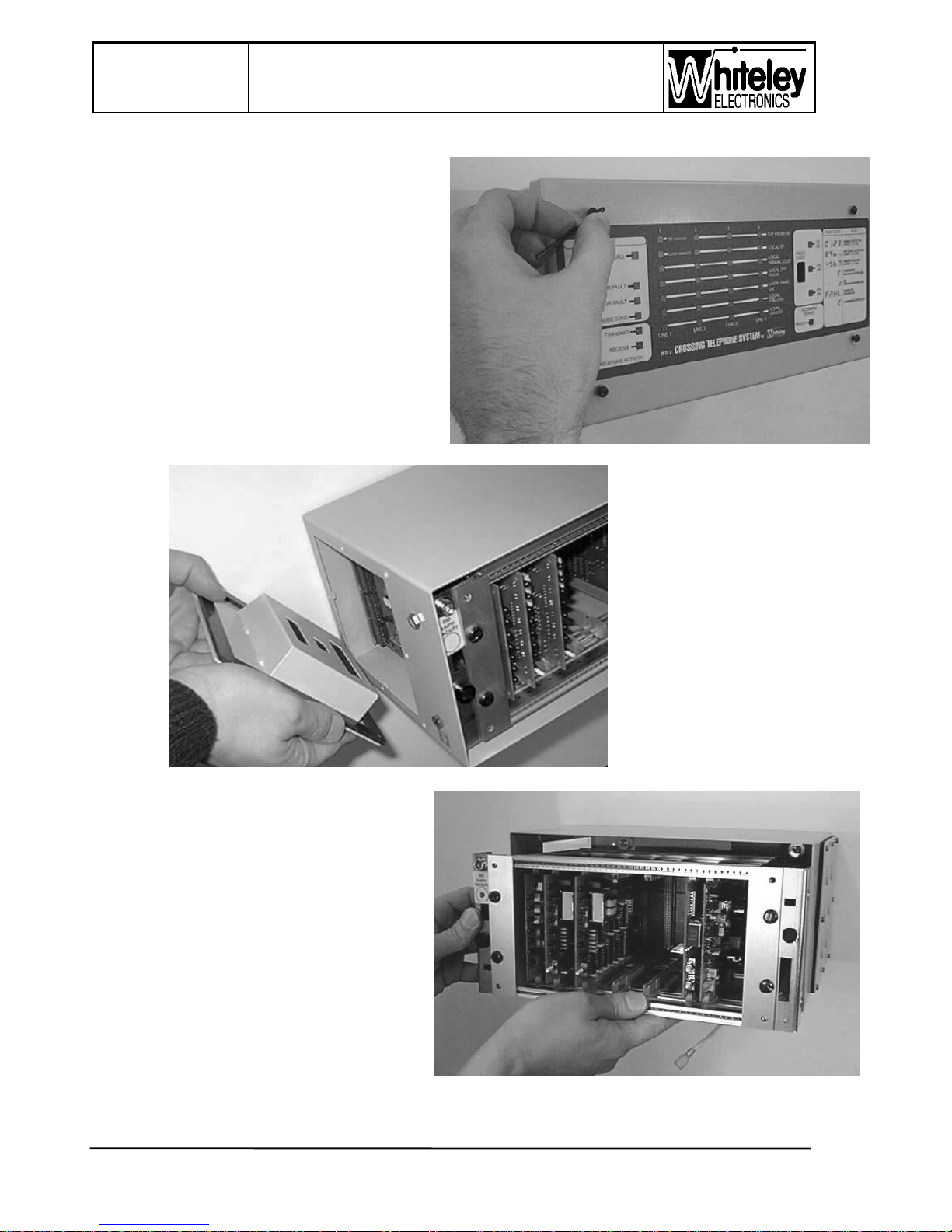
It is necessary to disassemble the PETS 2 unit, the procedure is identical for Signal Box
and for the Level Crossing Units:
Page 20
Page 20 of 40
Issue 2
13/12/99
PETS-2 Crossing Telephone System
QUICKFIX INSTALLATION HANDBOOK
20
a) Remove the front panel by undoing the
four M4 fixing screws on the front panel,
using the 2mm Allen key. Keep the
screws and washers together, washers
are essential to prevent damage to the
Level Crossing front panel membrane/
label. The front panel will just lift off (the
Signal Box unit may require gentle
prising to remove the front panel from the
inner edges of the case). An earth lead
will be attached to the Level Crossing
front panel and its push fit spade can be
pulled away from the tag of the panel.
b) Remove the Card Pullers from their
stowage location on the right hand side.
A) Remove all eight M3
slotted head screws
(and their washers)
from the left hand
Connection Plate
and the Connector
Retention bracket.
This plate may be
lifted away from the
‘D’ connectors.
IMPORTANT: THIS
PLATE MUST BE
REMOVED BEFORE
ATTEMPTING TO
PULL THE CARD
FRAME FROM THE
CASE. DO NOT UNDO THE FRONT
FOUR M6 SLOTTED SCREWS .
b) Loosen the four M6 hexagonal head
bolts (two each side of the case), using
the 10mm ring spanner. Remove the
lower bolts each side, then support the
frame with one hand whilst removing
the two upper bolts. Pull the frame (still
attached to the left and right brackets)
out of the case. Remove the remaining
earth tag, at the rear of the case, to
allow the frame to be separated from
the case. Carefully stow all of the
removed items.
Page 21
PETS-2 Crossing Telephone System
QUICKFIX INSTALLATION HANDBOOK
Page 21 of 40
Issue 2
13/12/99
21
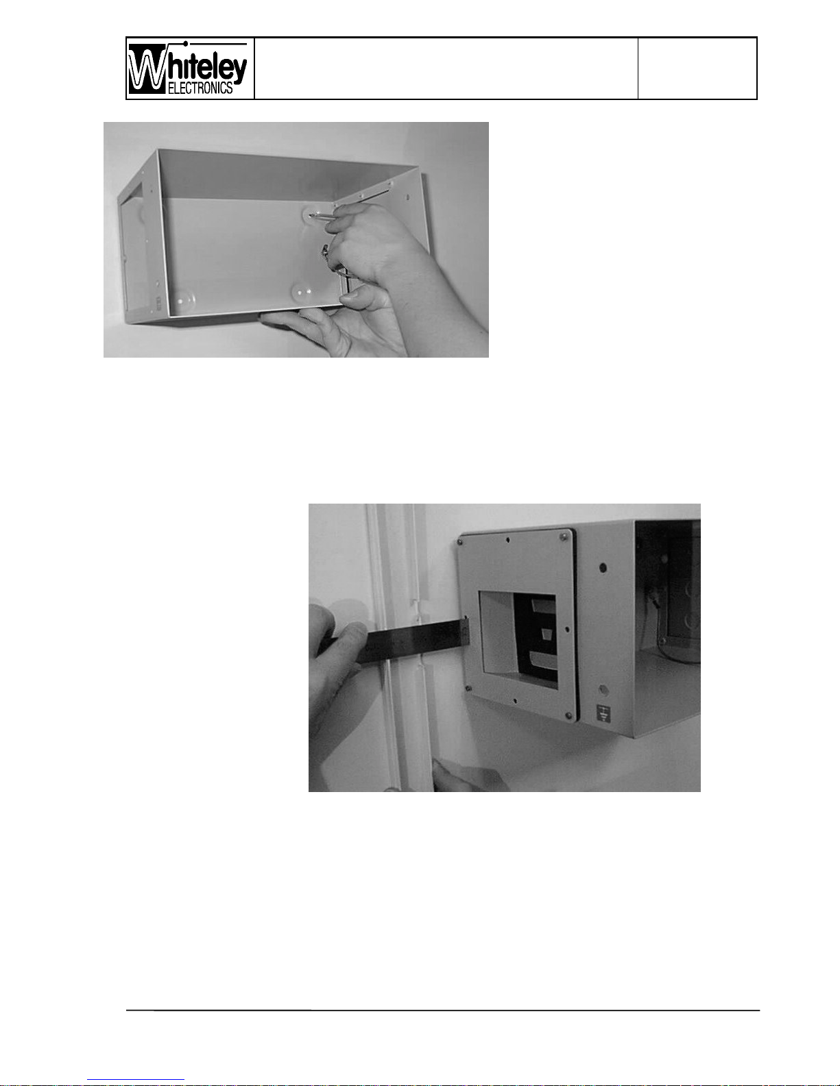
a) The case is now free of electronic
parts. Hold the case in the desired
installation position, making sure it
is level. IMPORTANT - THE
REAR FIXING HOLES ARE NOT
SYMETRICAL. THE WIDELEY
SPACED HOLES SHOULD BE
TOWARDS THE TOP, THE
EARTH TAG TO THE RIGHT.
Mark the four fixing positions
through the holes (in the centre of
the back panel ‘bumps’). Use the
most appropriate wall fixing
method, e.g. drill and plug for
masonry/ brick, make a pilot hole for wood and bolt/ or drill and tap for metal. When
installing the Level Crossing Unit in damp locations a rubber washer will be required
either at the back or directly under the screw head (a steel washer is recommended
between the screw head and the rubber washer); this arrangement is needed to prevent
water ingress through the fixing holes. IMPORTANT - CHECK TO ENSURE THE
SCREW HEAD PROTRUDES NO MORE THAN 4mm ABOVE THE BACK PANEL OF
THE CASE.
a) It may be useful to
temporarily fix with
just two screws whilst
trunking is fitted down
the left hand side.
The cables from each
connector exit
towards the wall; by
fitting the Connection
Plate the locations
may be identified.
Plastic trunking is
recommended, with
an end cap fitted to
the top of the
trunking, the trunking
cover can be modified
with cable cutters to create an entry point for each of the cables.
b) Check to ensure the case is installed level and is firmly fixed to the wall, the fixing screws
should be fully tightened.
c) Peel of the pieces of black PVC tape from the inside base of the case. Each piece
should be placed centrally over the wall fixing screw head. This will ensure the wall fixing
is sealed and is a precautionary measure to prevent contact with the rear of the frame
motherboard (when re-installed).
d) Fit the Junction Box to the wall. Its position may be determined by the trunking and the 2
metre cable length. At this stage a temporary fix is recommended.
Page 22
Page 22 of 40
Issue 2
13/12/99
PETS-2 Crossing Telephone System
QUICKFIX INSTALLATION HANDBOOK
22
e) If the left hand Connector Plate has been temporarily fitted - remove it now!
f) Install the frame back into the case (now fixed to the wall). Re-fit the internal earth tag.
Loose fit the M6 hexagonal bolts (starting with the top ones), fit the bottom left hand bolt
but this will be kept loose for now. Support the frame with one hand whilst re-assembling.
Make sure the frame is correctly positioned and tighten the three hexagonal bolts
(excluding the lower left side bolt - the earth bolt). Refer to section 5.5 before continuing.
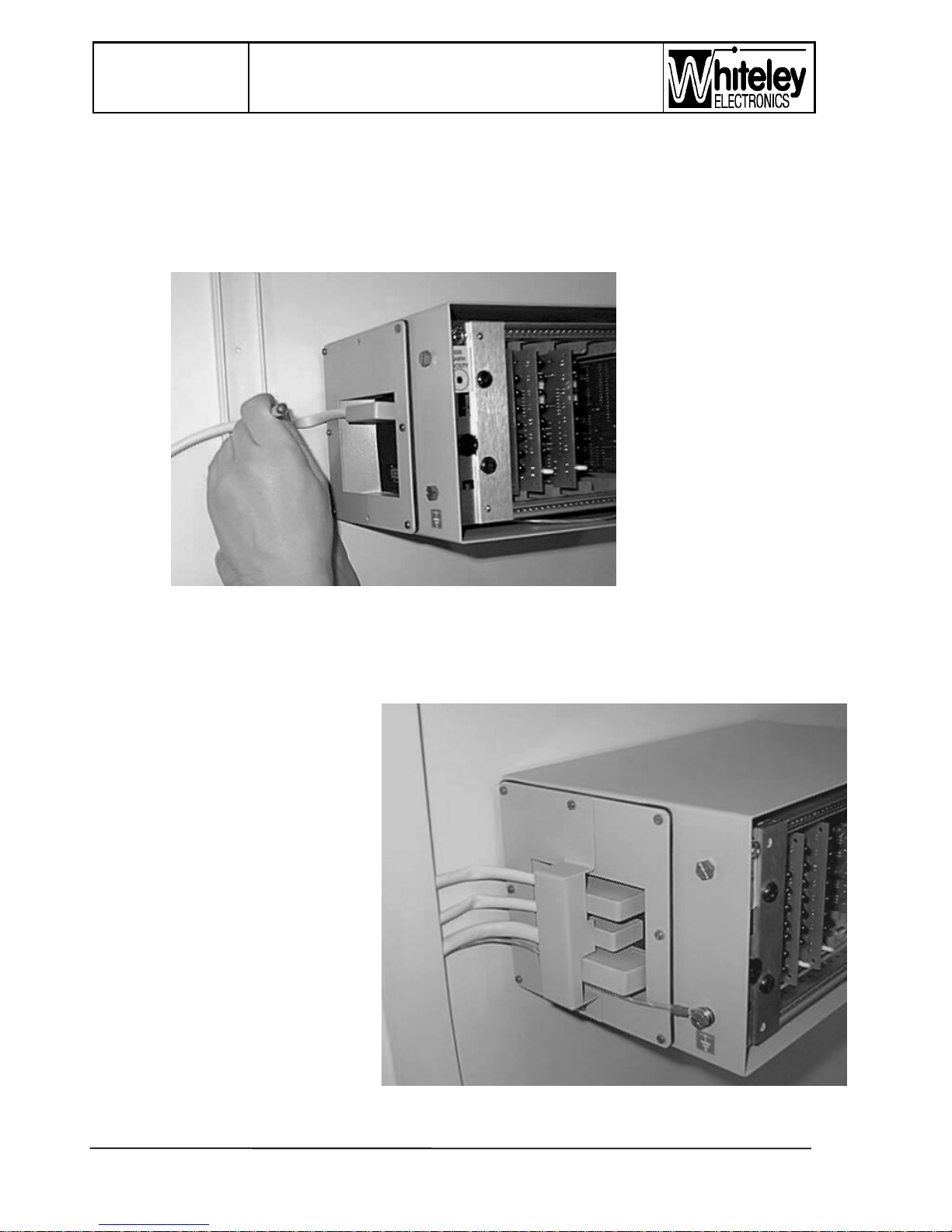
a) Re-fit the
Connection Plate,
making sure to keep
the rubber gasket
between the plate
and the outside of
the case. NOTE THIS GASKET IS A
NECESSARY
PART OF THE
SIGNAL BOX UNIT
SINCE IT
ESTABLISHES
THE DISTANCE
BETWEEN
CONNECTOR
PLATE AND
CONNECTOR PCB. THE THICK FOAM RUBBER GASKET INSIDE THE CONNECTOR
PLATE WELL, IS ONLY USED ON THE LEVEL CROSSING UNIT. Fit six M3 screws
and washers exclude the middle two required by the Connector Retention bracket.
b) Refer to section 5.8.1 and wire the 9 pin ‘D’ connector onto an appropriate length of
0.6mm telephone cable, to reach the power supply unit. NOTE: 0.5/0.6mm
a) Install each connector and
position the cables in a gentle
bend to the cable trunking, or
position into cable clips on the
wall. Making sure that the
connectors are fully mated and
aligned. Now fit the Connector
Retention bracket and its fixing
screws. Tighten the screws.
b) Now that the cables are
correctly positioned in the
trunking (or clipped to the wall),
the Junction Box can be
properly fixed to the wall.
Wall fixing is now complete.
5.5 Safety Earth
Page 23
PETS-2 Crossing Telephone System
QUICKFIX INSTALLATION HANDBOOK
Page 23 of 40
Issue 2
13/12/99
23
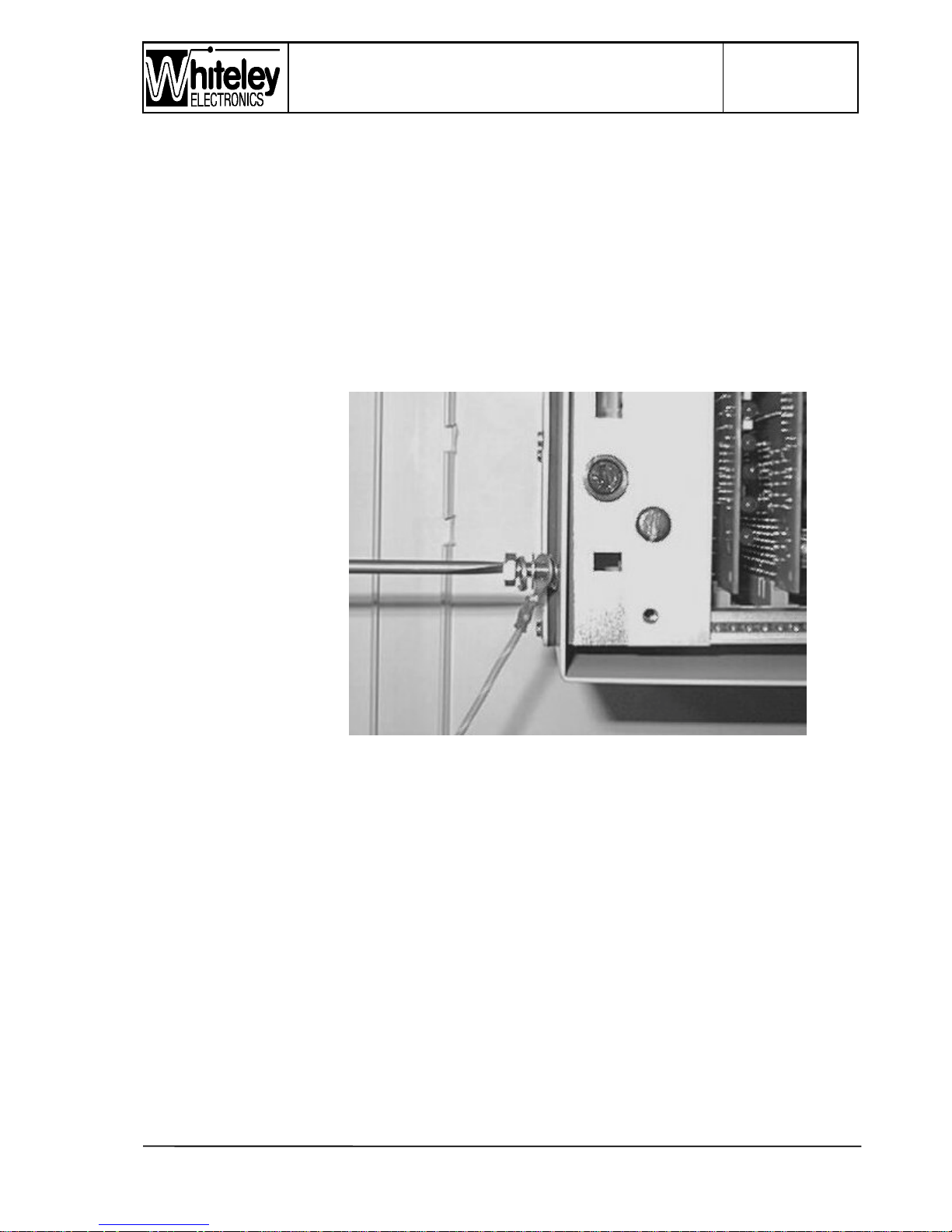
The lower left hand M6 hexagonal bolt is to be used for earthing the case. An earth label is
fixed to the case at the side of this bolt. This bolt was fitted with a crinkle washer, and this
washer is essential for integrity of the earth connection.
At this stage it is important to determine the system earthing policy. The case earth is
intended for the safety of the user and must be connected to the same earth point as the
surrounding electrical equipment. This will generally be the same point as the
telecommunications earth point within the Junction Box, and the green /yellow wire along
with the earth bond connection will be made together. In some instances, the case may be
fixed to a signalling frame and the integrity of earthing on the frame must not be affected.
Under these circumstances the PETS 2 unit (case) will be bonded to the local safety earth
of the signalling equipment, and telecommunications earth will be kept isolated.
The hexagonal bolt and
ring terminal are fitted
with the following items
and order:
M6 bolt - split washer plain washer - ring
terminal - crinkle washer
- case
The green/ yellow wire
is to be threaded
through the Connector
retention bracket and
then into the trunking.
In most applications the
green/ yellow wire will be terminated to the earth point in the Junction Box.
The ‘Telecommunications Earth’ inside the Junction Box will be terminated to an
appropriate earth point in accordance with normal telecommunications practise.
5.6 Configuration
This handbook will not describe the various configurations that are possible; in this section
the factory set configuration will be described. Any changes to configuration should be
detailed in the Installation Method Statement to be provided by the System design
Authority. Both units are factory configured to the most common applications, factory set
configurations are summarised over:
Page 24

Page 24 of 40
Issue 2
13/12/99
PETS-2 Crossing Telephone System
QUICKFIX INSTALLATION HANDBOOK
24
5.6.1 Signal Box Unit
a) Operating mode is ALL CALL - this means that Line 1 of the Signal Box Unit is mapped
to Lines 1, 2, 3 & 4 of the Level Crossing Unit (Lines 3 & 4 are not normally equipped on
the Level Crossing Unit).
b) Call Signalling Relay contact - this controls a remote call sounder and is set to operate
continuously.
c) Line circuit type - this is set to operate with a control telephone on Line 1
d) Software - the Signal Box unit is obviously configured to operate with Signal Box
software.
e) Signal Box Location - the unit is factory set as the terminating Signal Box, i.e. not as an
intermediate as part of a block switching scheme.
f) Transmission circuits - set for four wire operation
g) Data Update - Intrude tone is applied and manual operation of the INTERROGATE
button is required to update status.
5.6.2 Level crossing Unit
a) Intrusion tone on I/O change - set to disabled (NB In the original PETS this function was
enabled. The previous use of I/O was for barrier signalling. Now that the I/O is used for
equipment alarms it is not imperative that the Signaller is alerted during a call).
b) Second Caller - when a second telephone is operated (paired or solo), the second caller
will receive ring tone until the Signaller answer that call.
c) Each of the equipped line cards are configured for 2 wire Loop Disconnect calling.
d) Transmission circuit - set to four wire operation
Page 25
PETS-2 Crossing Telephone System
QUICKFIX INSTALLATION HANDBOOK
Page 25 of 40
Issue 2
13/12/99
25
5.7 Front panels
After re-installing the card frame into the case; fitting the Connection Plate, connectors and
Connector Retention bracket, the front panels may be replaced.
5.7.1 Signalbox front panel
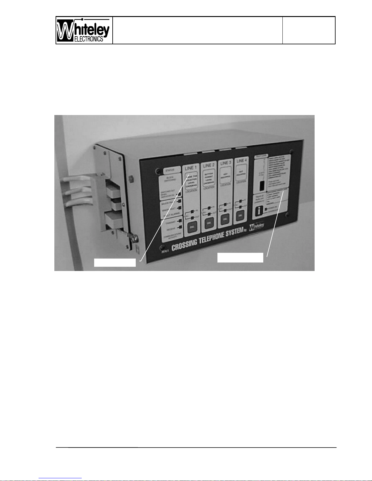
Figure 5 - Signalbox Unit showing label inserts
The panel is to be labelled with the following information:
1. Maintainer contact information for fault reporting by the Signaller.
2. Location (in terminology used by the Signaller) of each Level Crossing supported by the
unit.
3. Identification of unused Line circuits (labelled ‘Not Equipped’)
A Word 6 document file is available with the labels already formatted and sized. This file
is available upon request by return of e-mail. Please request along with your name,
position, company and phone number to the following address:
[email protected]
Simply open the file in Word 6 and enter the correct details in the pre-formatted areas.
Print onto good quality Laser/ inkjet paper and cut-out the labels using scissors and the
black outline borders as a guide. Insert the labels into the ‘pockets’ at the top and right
Location label
Maintainer label
Page 26
Page 26 of 40
Issue 2
13/12/99
PETS-2 Crossing Telephone System
QUICKFIX INSTALLATION HANDBOOK
26
hand edges of the Signalbox front panel. The ‘window’ should be centrally positioned
around the label.
The Signalbox front panel does not require a separate earth wire since it makes
continuous metallic contact with the card frame.
Buttons on the Line cards for the CALL function, and on the CPU card for the
INTERROGATE function, are equipped with a screw on cap. The shaft of the push
button switch is threaded, and the round cap is also threaded. The height may be varied
by threading the cap onto the push button. This is factory adjusted and sealed. The cap
is adjusted so that is pushes the membrane slightly forward, it should be possible to ‘feel’
the cap pressing from behind central to the CALL button membrane area. The CALL
button should have a tactile feel, a ‘click’ should be felt. The cap is screwed up or down
to adjust this action. IMPORTANT - THE THREAD IS SEALED AT FACTORY. IF THE
SEAL IS BROKEN - TOO MUCH ADJUSTMENT OUT WILL CAUSE THE MEMBRANE
TO PERMANENTLY OPERATE THE BUTTON, TOO LITTLE AND IT MAY NOT BE
POSSIBLE TO OPERATE THE BUTTON.
The panel is fixed by four M4 Allen key button head screws.
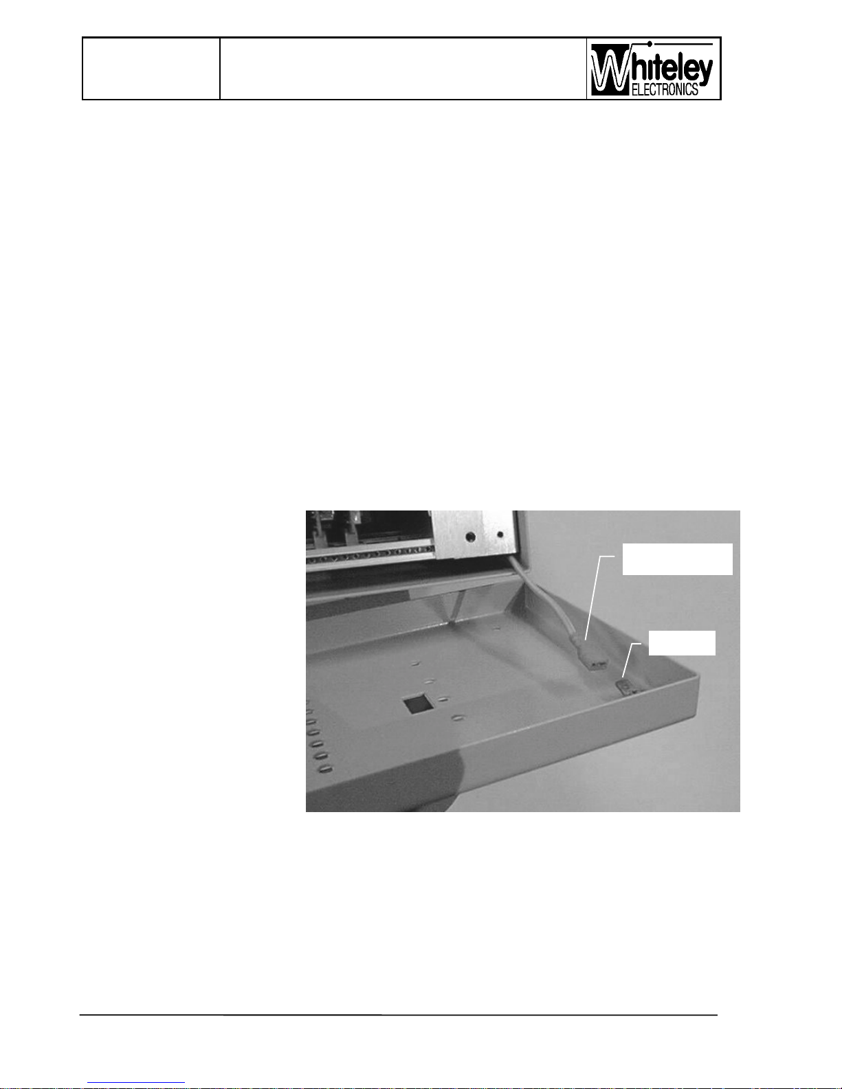
5.7.2 Level Crossing Unit front panel
An earth tag is provided on
this panel, ensure that it is reconnected when the panel is
fitted.
This panel has a foam rubber
gasket seal around its inside
edge. The panel is fixed by
four M4 Allen key button head
screws, ensure that washers
are used under the screw
heads to avoid distortion of
the label.
Figure 6 - Level crossing
Unit (front panel earth tag)
Earth tag
0.25” earth
spade connector
Page 27
PETS-2 Crossing Telephone System
QUICKFIX INSTALLATION HANDBOOK
Page 27 of 40
Issue 2
13/12/99
27
5.8 Wiring
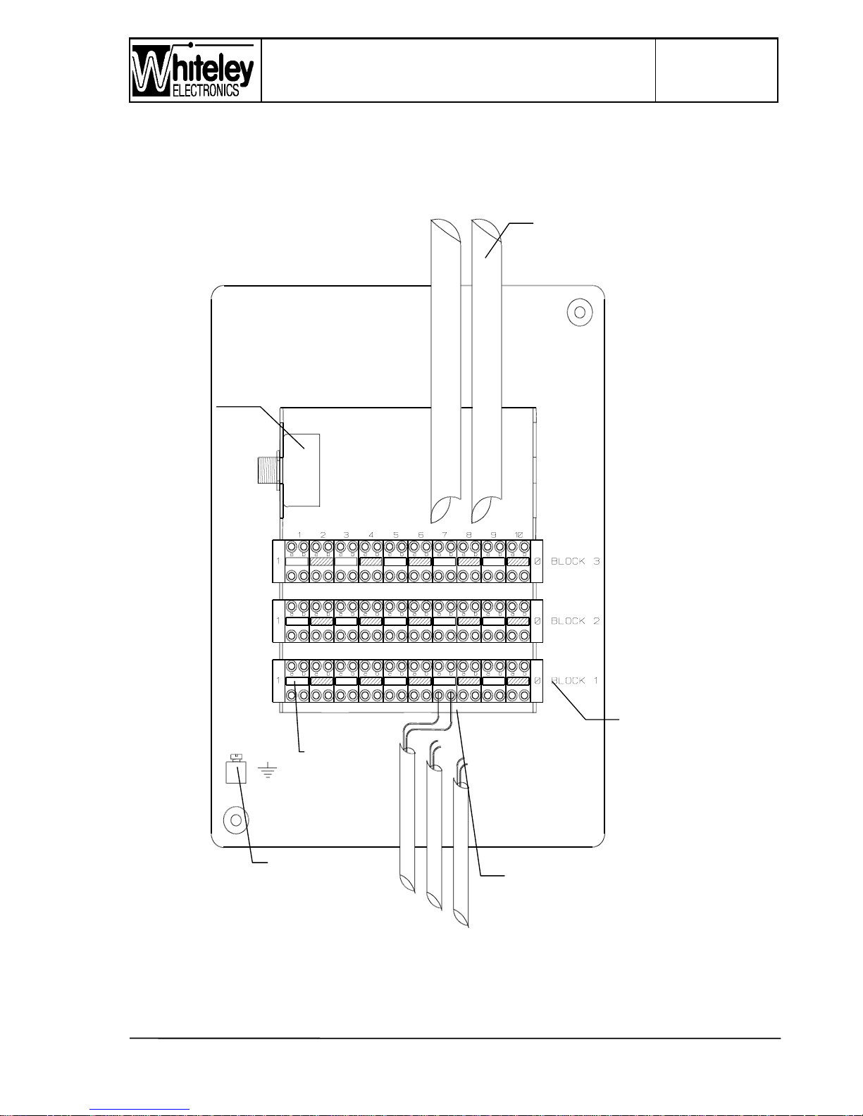
The Junction boxes at each end have similar wiring, the following tables summarise the
situation:
Figure 7 - Internal layout - Junction Box
Sounder for
equipment
alarms. Fitted
to Signal Box
JB only
Cables to ‘D’ connectors
on the PETS 2
equipment
External cables to telephone,
transmission circuits etc. taken
from this side of the QDF
Pair 1 end
Telecommunications
protective earth.
Block 1
Page 28
Page 28 of 40
Issue 2
13/12/99
PETS-2 Crossing Telephone System
QUICKFIX INSTALLATION HANDBOOK
28
BLOCK 1 - the lower block, nearest the earth bar (pair1 to the left)
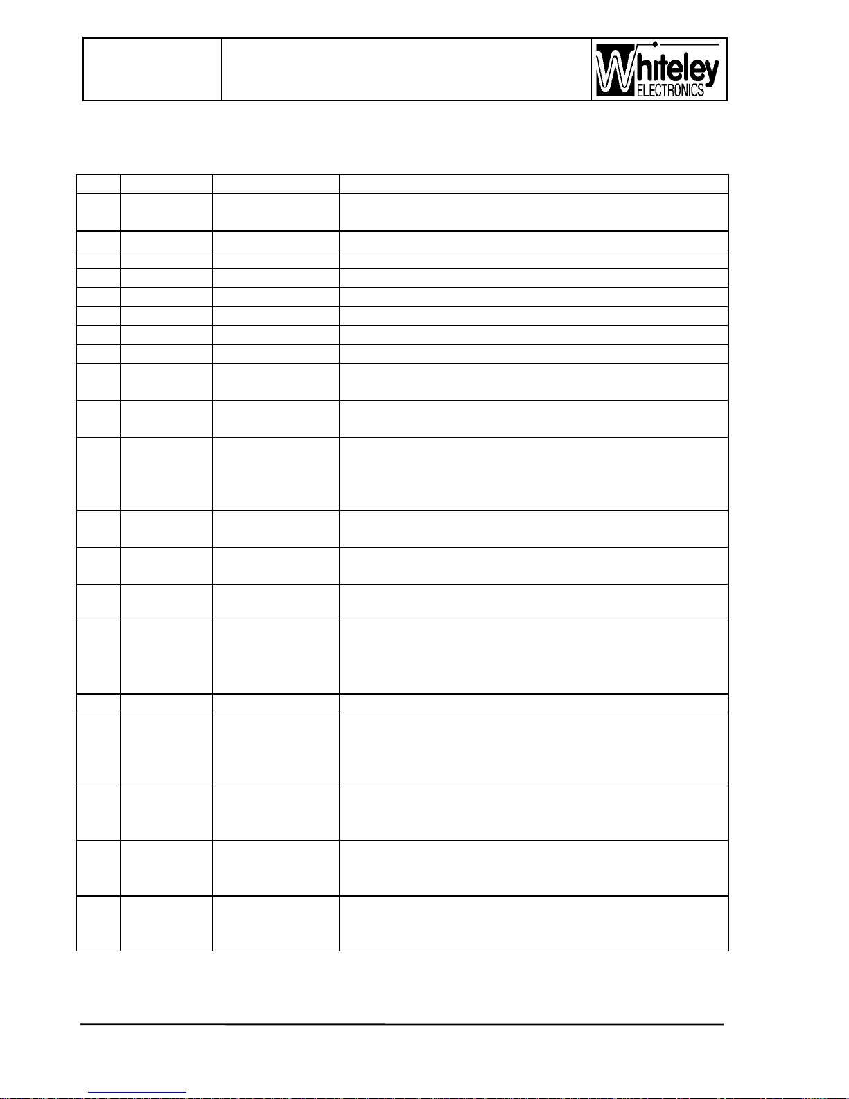
Pair Signalbox Level Crossing Description
1a Anode
com.
NA -Note 1 Remote Alarm Display - 7 segment display
1b cathode D NA Remote Alarm Display - 7 segment display
2a cathode C NA Remote Alarm Display - 7 segment display
2b cathode G NA Remote Alarm Display - 7 segment display
3a cathode B NA Remote Alarm Display - 7 segment display
3b cathode E NA Remote Alarm Display - 7 segment display
4a cathode F NA Remote Alarm Display - 7 segment display
4b cathode A NA Remote Alarm Display - 7 segment display
5a Button a NA Remote Alarm Display - Interrogate button contact,
normally open.
5b Button b NA Remote Alarm Display - Interrogate button contact,
normally open.
6a Input 1 &
Mains/
charger
alarm
Input 1 &
Mains/ charger
alarm
Line 1 control input. Connect to 0V to enable, shared
with power supply and charger alarm. This input is
forced to 0V by a parallel connected opto-transistor
when a mains/ charger alarm is activated.
6b Input 2 Input 2 Line 2 control input (Line 2 card is required for this to
function). Connect this input to 0V to become active.
7a Input 3 Input 3 Line 3 control input (Line 3 card is required for this to
function). Connect this input to 0V to become active.
7b Input 4 Input 4 Line 4 control input (Line 4 card is required for this to
function). Connect this input to 0V to become active.
8a +12V
fused,
100mA
limit
+12V fused,
100mA limit
Use this terminal for a local auxiliary supply. This
point is internally connected to the Output relays.
Note: the output relay can be commoned to 0V by
altering a link on the termination PCB.
8b 0V 0V Use this 0V to activate Inputs 2 to 4
9a Output 1 Output 1 This output is allocated to the mains/ charger alarm
from the distant site, and is configured to provide
+12V fused on this terminal in the event of mains/
charger alarm arriving from the other site.
9b Output 2 Output 2 Line 2 control output, will become +12V when Input 2
at the other site is connected to 0V. Line 2 cards
must be fitted at each site.
10a Output 3 Output 3 Line 3 control output, will become +12V when Input 3
at the other site is connected to 0V. Line 3 cards
must be fitted at each site.
10b Output 4 Output 4 Line 4 control output, will become +12V when Input 4
at the other site is connected to 0V. Line 4 cards
must be fitted at each site.
Page 29
PETS-2 Crossing Telephone System
QUICKFIX INSTALLATION HANDBOOK
Page 29 of 40
Issue 2
13/12/99
29
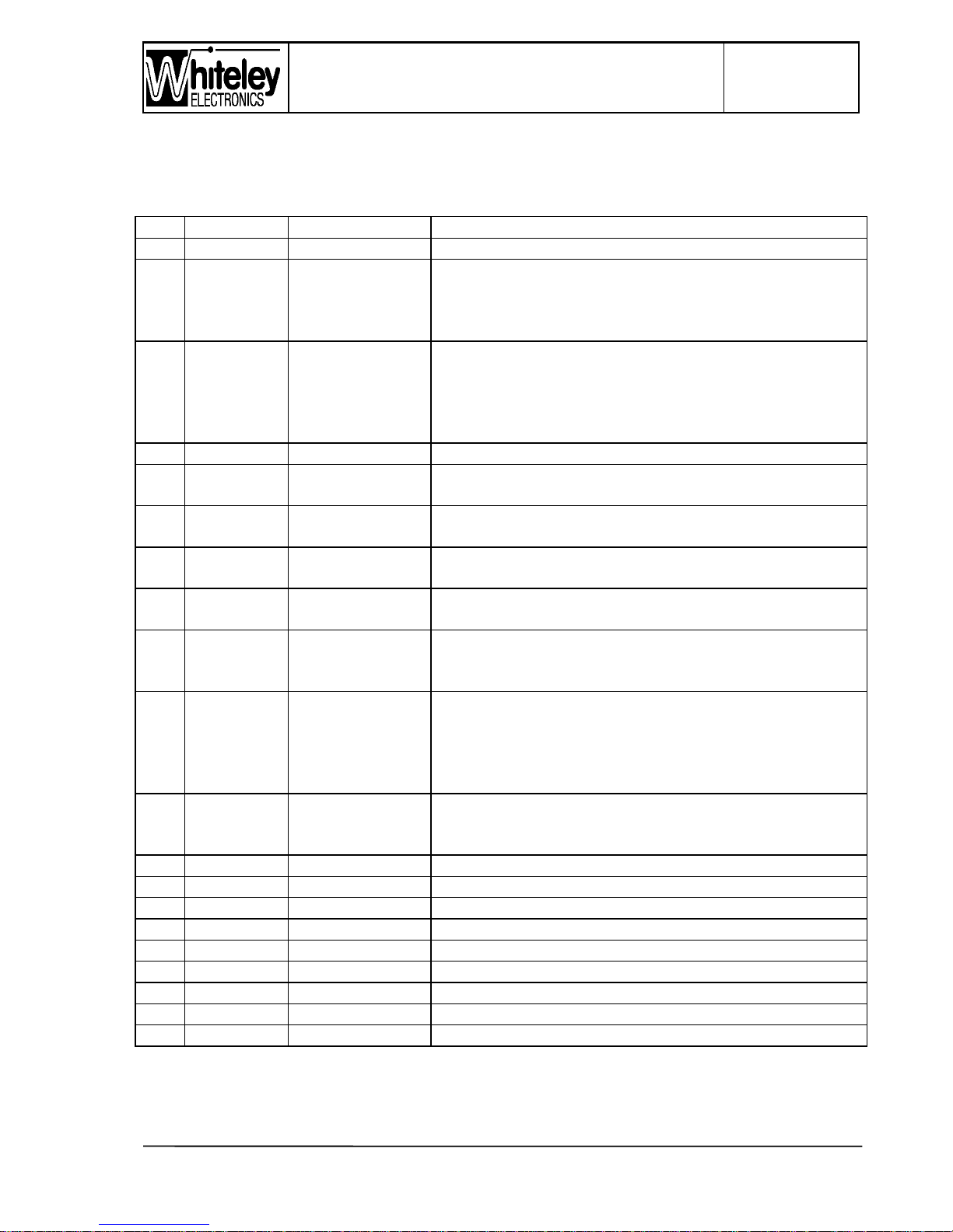
BLOCK 2 - the middle block (pair1 to the left)
Pair Signalbox Level Crossing Description
1a 0V 0V This is the same 0V as provided on Block 1
1b +12V
fused,
100mA
limit
+12V fused,
100mA limit
This is the same +12V fused as provided on Block 1.
The fuse for this circuit is located on the left hand
side bracket, beneath the ‘anti-static’ wrist strap
connection stud.
2a Call O/P a NA - function is
available, but it
is unlikely to be
used at the
crossing.
Volt free relay contact. Operates during an incoming
call ring, either continuous through the period of
ringing or in sympathy with ring cadence. This relay
would normally switch 50V dc to operate a remote
sounder.
2b Call O/P b NA Volt free relay contact, other side of 2a.
3a Alarm 1
O/P a
Alarm 1 O/P a MINOR alarm ( non - urgent) volt free contact
(normally open)
3b Alarm 1
O/P b
Alarm 1 O/P b MINOR alarm ( non - urgent) volt free contact
(normally open)
4a Alarm 2
O/P a
Alarm 2 O/P a MAJOR alarm (urgent) volt free contact (normally
open). Wired to the sounder in the Signalbox JB.
4b Alarm 2
O/P b
Alarm 2 O/P b MAJOR alarm (urgent) volt free contact (normally
open). Wired to the sounder in the Signalbox JB.
5a Block
switch-out
input +ve
NA Opto-isolated input +ve side. Apply 12V to 58V to
activate Block Switch (box closed/ transfer to distant).
5b Block
switch-out
input -ve
NA Opto-isolated input -ve side. This input is isolated and
it may be activated by a voltage from the signalling
equipment, ensure isolation is maintained.
Alternatively, wet the opto using the 0V/ +12V fused
through a volt free contact of the Block Switch.
6a ETH ETH Telecommunications safety earth. Local telephone
circuit cable screens, or earth connection when using
Earth Recall.
6b ETH ETH As above
7a Line 4 + # Line 4 + # short this leg to ETH for Earth Recall (ELR)
7b Line 4 - # Line 4 - #
8a Line 3 + # Line 3 + # short this leg to ETH for Earth Recall (ELR)
8b Line 3 - # Line 3 - #
9a Line 2 + # Line 2 + short this leg to ETH for Earth Recall (ELR)
9b Line 2 - # Line 2 10a Line 1 + Line 1 + SB control telephone. Short this leg to ETH for (ELR)
10b Line 1 - Line 1 - SB control telephone
Page 30
Page 30 of 40
Issue 2
13/12/99
PETS-2 Crossing Telephone System
QUICKFIX INSTALLATION HANDBOOK
30
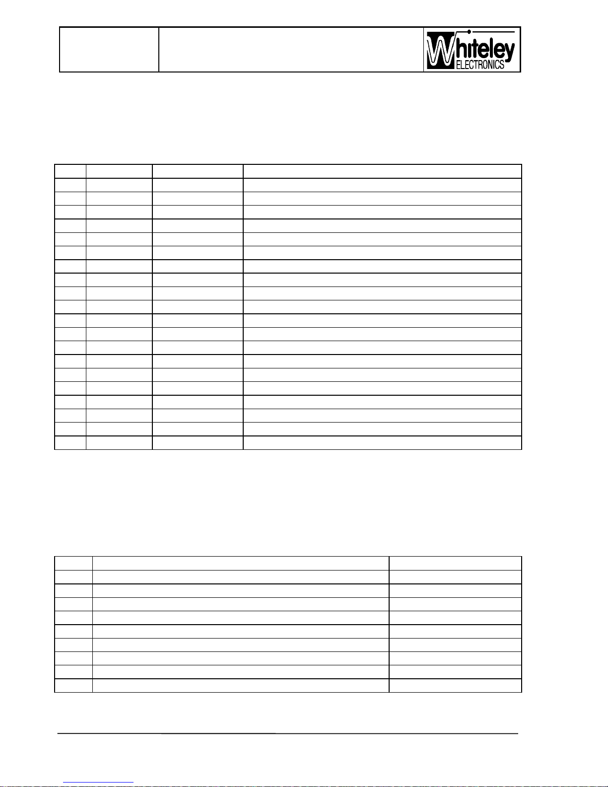
# = these line circuits are not equipped on standard units.
BLOCK 3 - the upper block (pair1 to the left)
NOTE: CONNECTIONS TO THIS BLOCK ARE ISOLATED FROM THE REST OF THE
SYSTEM - DO NOT JUMPER FROM BLOCK 3 TO THE OTHER BLOCKS.
Pair Signalbox Level Crossing Description
1a NC NC Spare
1b NC NC Spare
2a NC NC Spare
2b NC NC Spare
3a T4 (P) NA Block switching 4 wire (intermediate SB only)
3b T4 (O) NA Block switching 4 wire (intermediate SB only)
4a T4 (N) T4 (N) Four wire transmission Rx cct. Leg a
4b T4 (M) T4 (M) Four wire transmission Rx cct. Leg b
5a T3 (L) NA Block switching 4 wire (intermediate SB only)
5b T3 (K) NA Block switching 4 wire (intermediate SB only)
6a T3 (J) T3 (J) Four wire transmission Tx cct. Leg a
6b T3 (I) T3 (I) Four wire transmission Tx cct. Leg b
7a NA NA T2 relay ‘normally closed’ contact
7b NA NA T2 relay ‘normally closed’contact
8a T2 (F) NA Block switching 2 wire (intermediate SB only)
8b T2 (E) NA Block switching 2 wire (intermediate SB only)
9a T1 (D) NA Block switching 2 wire (intermediate SB only)
9b T1 (C) NA Block switching 2 wire (intermediate SB only)
10a T1 (B) T1 (B) Two wire transmission cct. leg a
10b T1 (A) T1 (A) Two wire transmission cct. leg b
5.8.1 Power supply
Power supply wiring descriptions are common to both Signal Box and level Crossing units.
Power supply connections are through the 9 pin (male) ‘D’ connector on the left hand side
of the case. The ‘D’ connector wiring is in accordance with the following table:
Pin Function Wire/ colour
1 Battery/ supply -ve (negative) -24V to 55V dc nominal 0.5mm/ 0.6mm, Pair 1a
2NC
3NC
4NC
5 Battery/ supply +ve 0.5mm/ 0.6mm, Pair 1b
6 Battery/ supply -ve -24V to 55V dc nominal 0.5mm/ 0.6mm, Pair 2a
7 Alarm - 0.5mm/ 0.6mm, Pair 3b
8 Alarm + 0.5mm/ 0.6mm, Pair 3a
9 Battery/ supply +ve 0.5mm/ 0.6mm, Pair 2b
Page 31
PETS-2 Crossing Telephone System
QUICKFIX INSTALLATION HANDBOOK
Page 31 of 40
Issue 2
13/12/99
31
Note 1: NC = Not Connected
Note 2: Pairs 1 & 2 are paralleled to provide adequate current rating, both pairs must be
used.
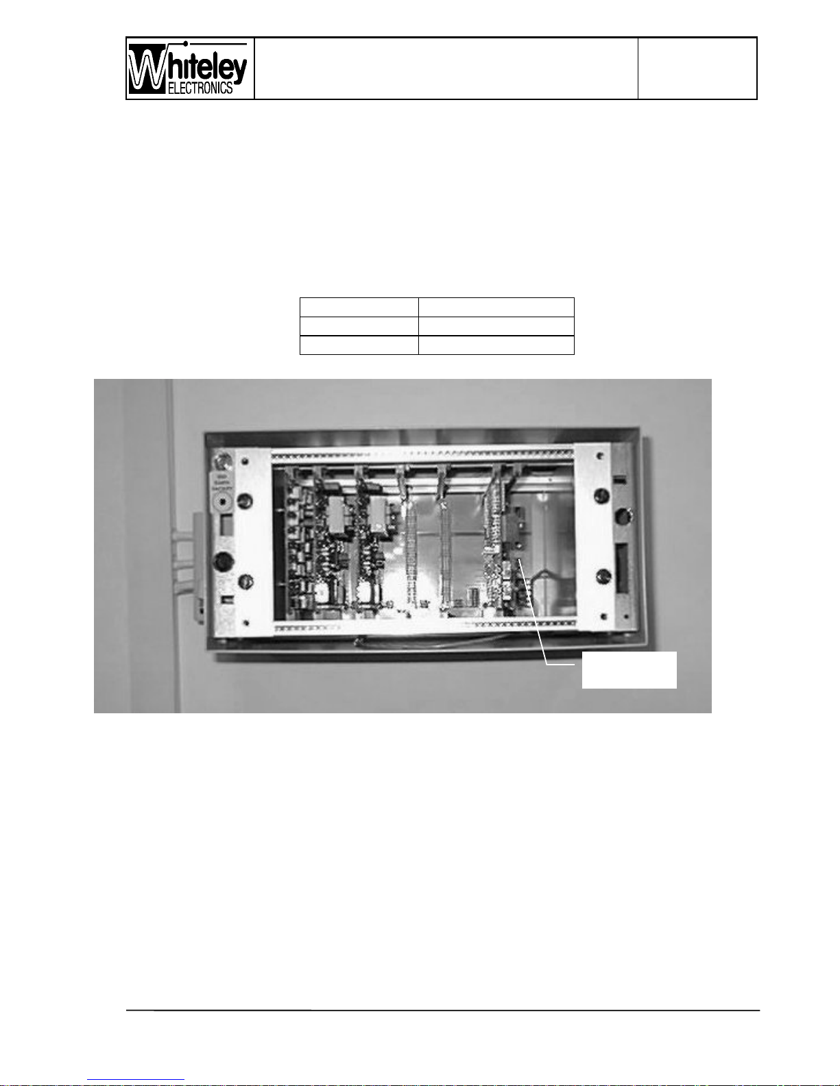
The Signal Box and Level Crossing Units are factory configured for 50V operation (to be
used with the PETS Power Supply & Battery Charger). Operation at 50V or 24V is
determined by a changeable link at the lower right hand side of the back-plane
motherboard, just above the screw terminals. The link is set as follows:
Link position Voltage range (dc)
A-B 20V to 35V
B-C 35V to 58V
Figure 8 - Power Supply voltage selector (applicable to SB & LC Units)
The Alarm circuit is an opto-isolated input that may be used with a voltage in the range 20V
to 58V. When the input is powered, an alarm indication is raised. This input is intended for
use with the PETS Power Supply and Battery Charger, and wiring instructions will
accompany that unit since differences will be found between the original charger and the
new model.
Voltage range
selection link
Page 32

Page 32 of 40
Issue 2
13/12/99
PETS-2 Crossing Telephone System
QUICKFIX INSTALLATION HANDBOOK
32
The ‘D’ connector is a solder bucket type. A small soldering iron is required to make these
connections. The pin number are moulded into the plastic adjacent to each pin - look close
as the number are very small.
5.8.2 Local telephone wiring (Level Crossing)
Local telephones are the crossing telephones (similar to signal Post telephones) or the
Equipment Room Control Telephone. Two different types of interface may be used, a brief
explanation of each is given in the following sections 5.8.2.1 & 5.8.2.2
Local telephone wiring connections are made onto QDF Block 2, pairs 7 to 10. When Earth
Recall operation is used, an earth is available on both legs of pair 6 of the QDF Block 2.
Please refer to Figure 7 for the layout of the QDF Blocks.
Earth Recall (ELR) is signalled by connecting ETH to Leg a (+ve) of the telephone line pair.
However, ELR will not be used normally and the units are factory configured for Loop
Disconnect calling. Loop Disconnect calling is preferrable as this method will operate over a
single pair ( ETH is not required by the telephone).
NOTE: Signal Post telephones designed for use at level crossings will normally incorporate
a ‘bell’ capacitor, and normal installation practise will allow the circuit to be wired directly to
the telephone. If ‘domestic’ type telephones are used in the equipment room, then a BT
Master LJU is to be used to interface the telephone with the PETS2 line circuit.
IMPORTANT NOTE: If overhead circuits are to be used, or if circuits operate parallel to
electrified lines, then protection magazines should be added to the QDF line circuits. In
cases of high risk of lightning or induced transient, then a separate transient suppresser/
lightning arrestor should be connected to the circuit, with its own safety earth.
5.8.2.1 Loop Disconnect Calling
NOTE: The line circuits are configured to this mode at factory.
This is the normal interface to be used on Crossing Telephones. This interface has the
advantage of being 2 wire (one pair). The ‘protocol’ is probably unique to PETS and has
three phases:
1. Quiescent Phase (telephone handset on hook) - a current of approx. 5mA flows in the
pair, and through a loop in the telephone handset
2. Off Hook Phase - current increase to >15mA
3. Calling Phase - current reduces f rom >15mA to zero for a defined period.
If the current remains at zero for more than 30 seconds, an alarm is logged; indicating the
possibility of an open circuit pair or vandalised handset.
Page 33
PETS-2 Crossing Telephone System
QUICKFIX INSTALLATION HANDBOOK
Page 33 of 40
Issue 2
13/12/99
33
Polarity is not important with this protocol. However, it is necessary to ensure that the
telephone is correctly wired and a ‘leakage current’ resistor has to be fitted to the
telephone.
5.8.2.2 Earth Recall
NOTE: The unit will require re-configuration to operate in this mode - seek instruction from
the System Design Authority.
This is a possible calling mode for a control telephone (in the level crossing equipment
room) connected to its own line card. Telephone line Leg a (+ve) is shorted to Earth
(telecommunications earth) to signal a call. This mode supports the monitoring of leakage
current, hence a resistor must be fitted across the line pair - normal inside the master LJU
of that telephone.
5.8.2.3 Master Line Jack socket for control telephone
Control telephones at the Signalbox and Level Crossing will normally be connected through
a standard master LJU. If ELR calling is required, then the polarity of wiring is important and
the socket should be polarity tested using a Linesman's Telephone.
If an ABSENT switch is installed in the Signalbox, it will be necessary to wire the Control
telephone line through a normally closed contact of the ABSENT switch, to ensure that the
telephone does not ring when the box is closed. Some arrangement with automatic
announcers will require the ABSENT switch to divert the line to the announcer unit.
5.8.3 Transmission Circuits
The Signalbox Unit and Level Crossing Unit have to be connected together via a
transmission medium. This medium may be physical (copper) or by means of a multiplexor (
D & I Mux, PCM link etc.). PETS2 may be configured for a 2 wire (one pair; bi-directional) or
a 4 wire (two pair; go & return, Tx/ Rx) circuit. If the facility is available, choose a 4 wire
interface since this will provide better transmission performance and will be easier to f ault
find if there are transmission difficulties. Use a 2 wire interface on physical circuits where
pairs are in short supply. Seek expert advise for the modifications required to allow 2 wire
operation. This handbook assumes that the installation will use factory default configuration
of 4 wire operation. In this mode, the pair labelled T3 are the transmit circuit, i.e. audio is
transmitted out on T3. The circuit labelled T4 is the receive circuit. Transmit of the
Signalbox is connected to receive of the Level Crossing. Phasing of the pair is not
important, but it is good practise to maintain phasing. The transmission circuits should be
connected as follows:
Signalbox JB Crossing JB Cable Colour (mark up)
(T3-Tx) Block 3, pair 6a (T4-Rx) Block 3, pair 4a
(T3-Tx) Block 3, pair 6b (T4-Rx) Block 3, pair 4b
(T4-Rx) Block 3, pair 4a (T3-Tx) Block 3, pair 6a
(T4-Rx) Block 3, pair 4b (T3-Tx) Block 3, pair 6b
Page 34

Page 34 of 40
Issue 2
13/12/99
PETS-2 Crossing Telephone System
QUICKFIX INSTALLATION HANDBOOK
34
The simple arrangement above is the most common form of installation. A more complex
arrangement would be detailed by the System design Authority if ‘Block Switching’ is
required.
5.8.4 Miscellaneous Wiring
The functions of each circuit are detailed in the table of section 5.6 The hardware of
Signalbox and level crossing Units is identical and some circuits are redundant, particularly
at the Level crossing end. This section will briefly summarise some of the possible
alternative functions, but will not detail the installation method since this will be provided by
the System Design Authority if required:
• 2 wire operation - a dedicated transmission circuit pair (T2) is allocated to operation over
a since pair. PETS incorporates an electronic hybrid based upon 600R operation.
• Block switching - a Level Crossing unit may be controlled by different Signalboxes (at
different times). Circuit T2 is used for switching the transmission circuit under control of
the Block Switch of an Intermediate Signalbox. A dc control circuit is provided to allow for
an input signal from a common ‘Block Switch’ in the Signalbox.
• Alarm Outputs - Major and minor alarm outputs are available on volt free contacts for
connection to automatic fault reporting systems (SCADA).
• External Call Sounder - In some instances the Signalbox equipment may be remote from
the Signaller and require a separate call sounder. volt free relay contacts are provided for
this purpose.
• Command, control and monitoring - sometimes it is necessary to transmit low priority
alarms between Signalbox and crossing. PETS2 allocates Line 1 at each end for bidirectional signalling power supply and charger failure alarms. Three additional signalling
circuits are available if a full compliment of Line cards are equipped at each end. These
I/O circuits are pre-wired to the QDF blocks in each Junction Box.
• Remote Alarm Display - this new product for use with the Signalbox Unit may be wired
into the QDF connections of Block 1, allowing alarms to be remotely viewed and
acknowledged.
Page 35

PETS-2 Crossing Telephone System
QUICKFIX INSTALLATION HANDBOOK
Page 35 of 40
Issue 2
13/12/99
35
6. TECHNICAL DATA
6.1 Mechanical details
DIMENSIONS (Level Crossing model) :
width (including connectors) - 252 mm
width (case only) - 324 mm
height (case only) - 160 mm
depth (including wall stand-off) - 210 mm
Note: Signalbox unit is slightly smaller due to different front panel arrangement)
WEIGHT : 5.3 Kg.
COLOUR : RAL7032
6.2 Electrical
POWER SUPPLY: 20V dc to 58V dc, in two ranges
CURRENT: 0.425A @ 24V dc / 0.25A @ 50V dc
AUXILIARY 12V SUPPLY: maximum load current 0.1A - fused @ 0.1A
OPTO INPUTS: operating range 12V dc to 58V dc
RELAY OUTPUT RATING: 100V dc @ 0.3A, 30V dc @ 1A
6.3 Telephony
6.3.1 Telephone Circuits
REN RATING: maximum of REN = 2 per line
MAX. LOOP RESISTANCE: 1000R
MATCHING Z: 600R
LOOP LEAKAGE (QUIESCENT): 6mA nominal {>2mA, <8mA}
LOOP TRIP: >15mA
6.3.2 Transmission
MATCHING Z: 600R
Page 36

Page 36 of 40
Issue 2
13/12/99
PETS-2 Crossing Telephone System
QUICKFIX INSTALLATION HANDBOOK
36
AVERAGE LINE LEVEL: -13dB(m)
ISOLATION: 3.5KV ac rms. (to BS6301)
RETURN LOSS: >15dB (ref. 600R) 300Hz to 3.4KHz
BALANCE RETURN LOSS: >65dB to earth
MAXIMUM TRANSMISSION PATH ATTENUATION: 20dB resistive to guarantee DTMF
operation, but gain compensation is recommended if the loss is >10dB, to maintain
satisfactory speech performance.
6.4 Environmental
OPERATING TEMPERATURE : -20°C to 50°C
STORAGE TEMPERATURE : -25° to 70°C
ENCLOSURE PROTECTION : BS54520, IP55 (Level Crossing Unit only, and its Junction
Box should be protected from dripping water)
EMC EMISSIONS - EN 55022
EMC SUSCEPTIBILITY - EN 61000-4-3, EN 61000-4-4, EN 61000-4-5, EN 61000-4-6,
Page 37
PETS-2 Crossing Telephone System
QUICKFIX INSTALLATION HANDBOOK
Page 37 of 40
Issue 2
13/12/99
37
Appendix A
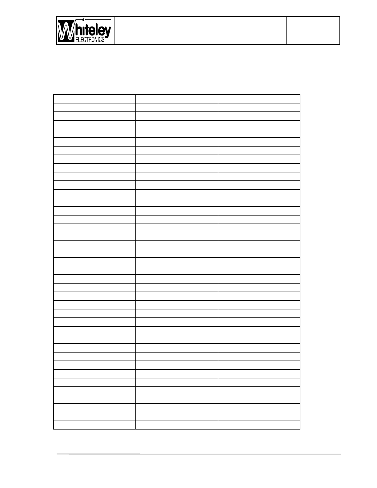
Cable Schedule - ‘D’ connectors to Junction Box QDF’s
Control & Alarm Connection Lead ( 20 pair )
From Colour To
Block 1, 1a WHITE – Blue 50 way D pin 2
- 1, 1b BLUE – White - 1
- 1, 2a WHITE – Orange - 18
- 1, 2b ORANGE – White - 34
- 1, 3a WHITE – Green - 35
- 1, 3b GREEN – White - 36
- 1, 4a WHITE – Brown - 37
- 1, 4b BROWN – White - 38
- 1, 5a WHITE – Grey - 3
- 1, 5b GREY – White - 19
- 1, 6a RED – Blue - 47
- 1, 6b BLUE – Red - 45
- 1, 7a RED – Orange - 43
- 1, 7b ORANGE – Red - 41
- 1, 8a Not connected to D
connector
See jumpers below
- 1, 8b Not connected to D
connector
See jumpers below
- 1, 9a RED – Brown - 48
- 1, 9b BROWN – Red - 46
- 1, 0a RED – Grey - 44
- 1, 0b GREY – Red - 42
- 2, 1a BLACK – Blue - 39
- 2, 1b BLUE – Black - 40
- 2, 2a BLACK – Orange - 49
- 2, 2b ORANGE – Black - 50
- 2, 3a BLACK – Green - 16
- 2, 3b GREEN – Black - 14
- 2, 4a BLACK – Brown - 33
- 2, 4b BROWN – Black - 15
- 2, 5a BLACK – Grey - 13
- 2, 5b GREY – Black - 12
- 2, 6a YELLOW – Blue - 17
- 2, 6b Not connected to D
connector
See jumpers below
- 2, 7a YELLOW – Orange - 4
- 2, 7b ORANGE – Yellow - 5
- 2, 8a YELLOW – Green - 6
Page 38
Page 38 of 40
Issue 2
13/12/99
PETS-2 Crossing Telephone System
QUICKFIX INSTALLATION HANDBOOK
38
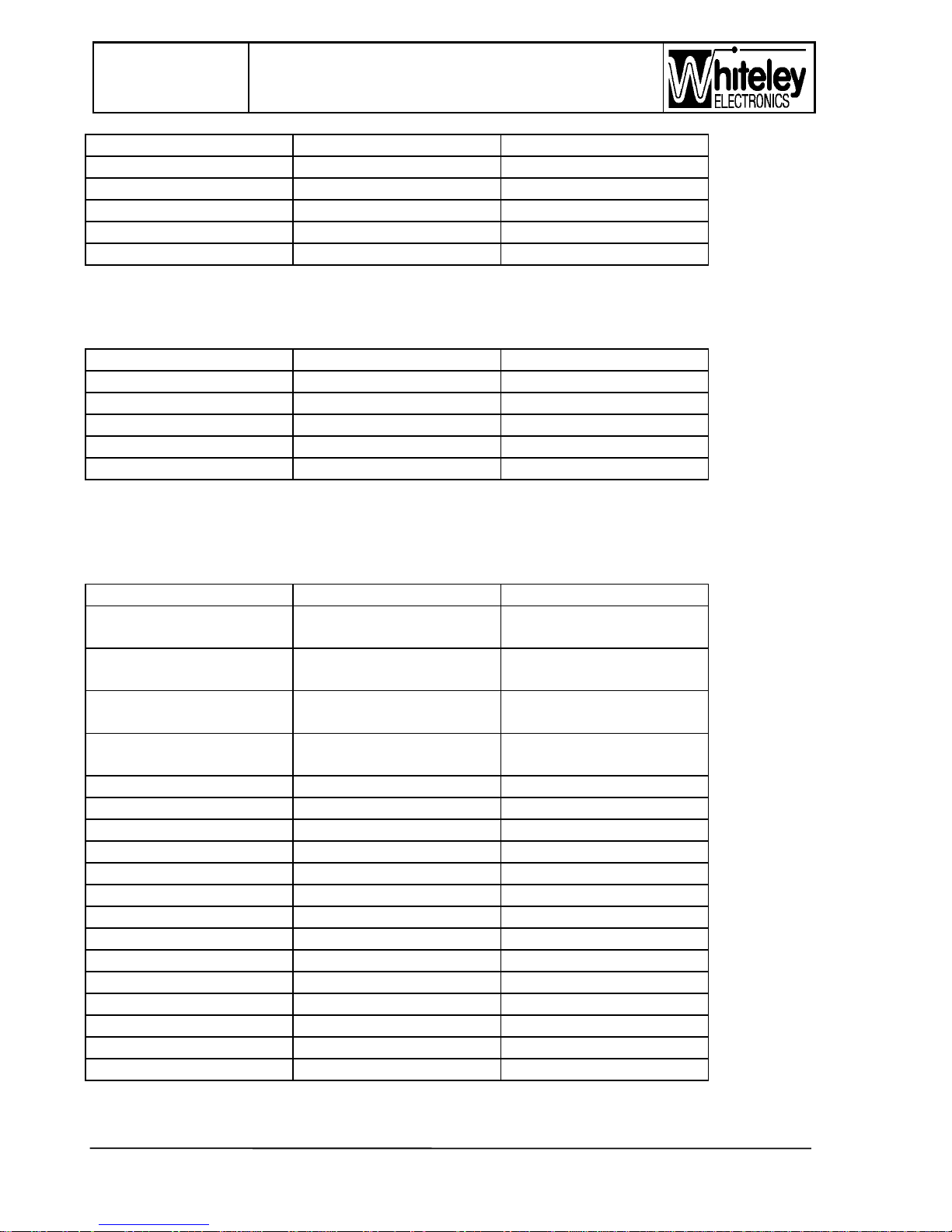
From Colour To
- 2, 8b GREEN – Yellow - 7
- 2, 9a YELLOW – Brown - 8
- 2, 9b BROWN – Yellow - 9
- 2, 0a YELLOW – Grey - 10
- 2, 0b GREY – Yellow - 11
Jumpers
From Colour To
Block 2, 1a GREEN – Red Block 1, 8b
Block 2, 1b RED – Green Block 1, 8a
Block 2, 6a BLUE - Yellow Earth post
Block 2, 6a BLUE - Yellow Block 2, 6b
Block 2, 4a WHITE – Blue Block 1, 8a
Telecommunications Connection Lead ( 10 pair )
From Colour To
Block 3, 1a Not connected to D
connector
Spare
- 3, 1b Not connected to D
connector
Spare
- 3, 2a Not connected to D
connector
Spare
- 3, 2b Not connected to D
connector
Spare
- 3, 3a WHITE – Green 25 way D pin 14
- 3, 3b GREEN – White - 15
- 3, 4a WHITE – Brown - 1
- 3, 4b BROWN – White - 2
- 3, 5a WHITE – Grey - 6
- 3, 5b GREY – White - 4
- 3, 6a RED – Blue - 3
- 3, 6b BLUE – Red - 5
- 3, 7a RED – Orange - 13
- 3, 7b ORANGE – Red - 25
- 3, 8a RED – Green - 11
- 3, 8b GREEN – Red - 12
- 3, 9a RED – Brown - 10
- 3, 9b BROWN – Red - 8
Page 39
PETS-2 Crossing Telephone System
QUICKFIX INSTALLATION HANDBOOK
Page 39 of 40
Issue 2
13/12/99
39
From Colour To
- 3, 0a RED – Grey - 7
- 3, 0b GREY – Red - 9
Sounder Wiring – Black to Block 1, 8b
Red & White to Block 2, 4b
Page 40
Page 40 of 40
Issue 2
13/12/99
PETS-2 Crossing Telephone System
QUICKFIX INSTALLATION HANDBOOK
40
Appendix B
PETS 2 SIGNALBOX LABELS
MAINTAINER COMPANY NAME
STREET ADDRESS
TOWN ADDRESS
CITY & POST CODE
TEL:
CONTACT:
NOT
EQUIPPED
NOT
EQUIPPED
NOT
EQUIPPED
SUTTON
FOREST
LEVEL
CROSSING
NAME THE
LOCATION
LEVEL
CROSSING
A
lter the text within the boxes as required. Print this sheet on a Laser or Inkjet
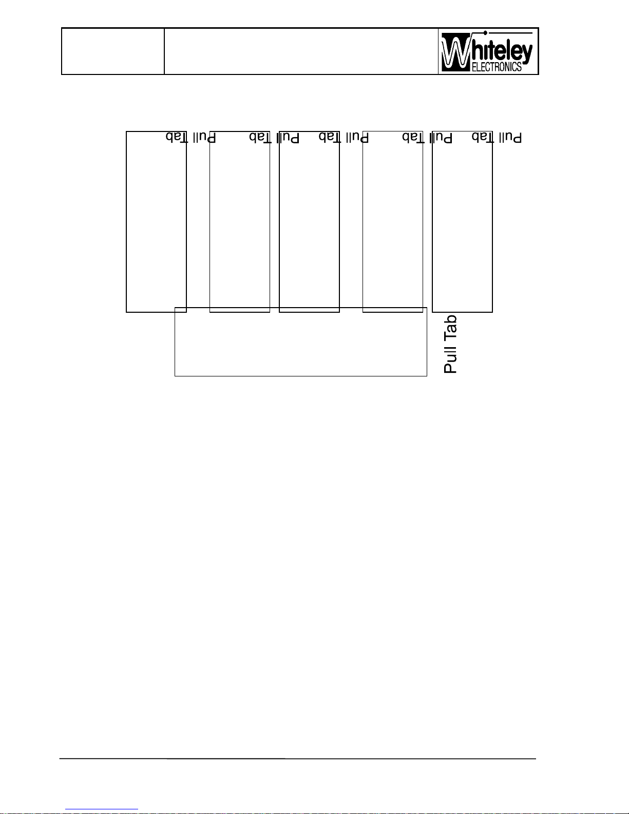
with accurate size mapping, use good quality paper. Cut out the labels around
the border edge using scissors, cut accurately to the edge. Slide into the edge
aperture of the front panel, if the size is correct it should slide in easily and the
white paper should fill the window area, some alignment may be needed. The
‘Pull Tab’ part will stick out from the front panel edge. Fold this part to the
inside so as to trap this tab when the front panel is re-fitted. Assembly can be
made easier by Sello-taping the Pull Tab to the rear of the front panel. The
‘Pull Tab’ will be needed to remove the label in the future.
Black PVC tape covers the apertures behind the Line Card windows. If Barrier
A
larm Signalling is to be used, drafting film is recommended to allow the
required LED’s to show through. Puncture the black PVC tape as required,
keep Line 1 blacked out since the Line 1 LED’s may operate with mains/
charger failure.
Whiteley Electronics Ltd. 23/1/98 G42278a issue 1
 Loading...