

Page 1
Manual available online at wkfluidhandling.com
CPT-1 Product Manual
Manual Version 1.3.1 Manual Part# 18200-LM-0038
Page 2

Table of Contents
1. System Recommendations .................................................................................................................................1
1.1 Precautions .......................................................................................................................................................1
1.2 System Environment Recommendations/Requirements ..................................................................................1
1.3 Getting Started ..................................................................................................................................................1
2 Parts List ..................................................................................................................................................................2
2.1 CPT-1 Cycle Rate Translator ............................................................................................................................2
2.2 Power Adapter with Crimp Pins ........................................................................................................................3
2.3 Cable: 44-Pin HD D-Sub to Wire Leads ...........................................................................................................3
2.4 Breakout Board: 44-Pin HD D-Sub to Screw Terminal .....................................................................................3
2.5 Din Rail Power Supply ......................................................................................................................................3
2.6 Quick Connect: 44-Pin HD D-Sub to Connectors .............................................................................................3
3 System Overview .....................................................................................................................................................3
4 Power and Communication .....................................................................................................................................4
4.1 Powering the CPT-1 ..........................................................................................................................................4
4.2 Ethernet Connection: ........................................................................................................................................5
4.3 RS-232 Connection: ..........................................................................................................................................5
5 Digital I/O Setup .......................................................................................................................................................5
5.1 Power Digital Ports ...........................................................................................................................................5
5.2 Digital Inputs: ....................................................................................................................................................5
5.3 Digital Outputs:..................................................................................................................................................7
5.4 Wiring Configurations ........................................................................................................................................8
6 PC to CPT-1 Communication: .................................................................................................................................9
6.1 Ethernet Connection: ........................................................................................................................................9
6.2 RS-232 Connection: ..........................................................................................................................................9
7 Software Setup: .......................................................................................................................................................9
7.1 Installation: ........................................................................................................................................................9
7.2 Using the Software: ...........................................................................................................................................9
7.3 Software Inputs: ............................................................................................................................................. 10
8 Troubleshooting Q & A: ........................................................................................................................................ 12
8.1 Issues connecting to CPT-1 via Ethernet: ..................................................................................................... 12
8.2 Issues Connecting to CPT-1 via RS-232: ...................................................................................................... 12
9 Appendix 1: Complete Wiring Guide Table .......................................................................................................... 13
Manual Version 1.3.1 Manual Part# 18200-LM-0038
Page 3

10 Appendix 2: Dimensional Diagrams ................................................................................................................... 16
DO NOT OPEN CONTROL BOX
Do not open up the control box. White Knight is not responsible for any damage caused by opening the
control box.
Environmental Temperature
This product is rated to withstand environmental temperatures up to 70°C.
Grounding
All electrical components must be ground to minimize risk of sparks. Follow proper procedures for
grounding all products in the system.
11 Ordering Instructions .......................................................................................................................................... 17
1. System Recommendations
1.1 Precautions
1.2 System Environment Recommendations/Requirements
1.3 Getting Started
Installing the CPT-1 for the first time it is recommended that you follow these steps:
1) Verify that you received all of the components that you ordered. Note: cables and breakout board for the
controller are options that can be selected at the time of purchase.
2) Check that you have a compatible power supply to power the controller. See Section 4.1
3) Check that you have a compatible communication cable for setting up the controller. See Sections 4.2 and 4.3
4) Download the setup software from www.wkfluidhandling.com/cpt-1.
5) Verify that your computer is able to connect to the controller.
a) Power up the controller with correct power source
b) Connect the communication cable correctly. (Ethernet cables should go from the controller to a network
switch, not your PC)
c) Install and launch the Smart Control Software.
d) The connections dialog should appear at launch. Verify that your controller appears on the list and click
the connect button. See Section 7
e) Once connectivity is verified disconnect from the software, and disconnect power and communication
cable.
6) Install CPT-1 in the desired location.
7) Connect 44-pin connector and use the wiring guide in Section 5 to connect system.
8) Connect to controller (same as before) and configure the CPT-1 settings to match your system needs.
Manual Version 1.3.1 Manual Part# 18200-LM-0038
Page 4
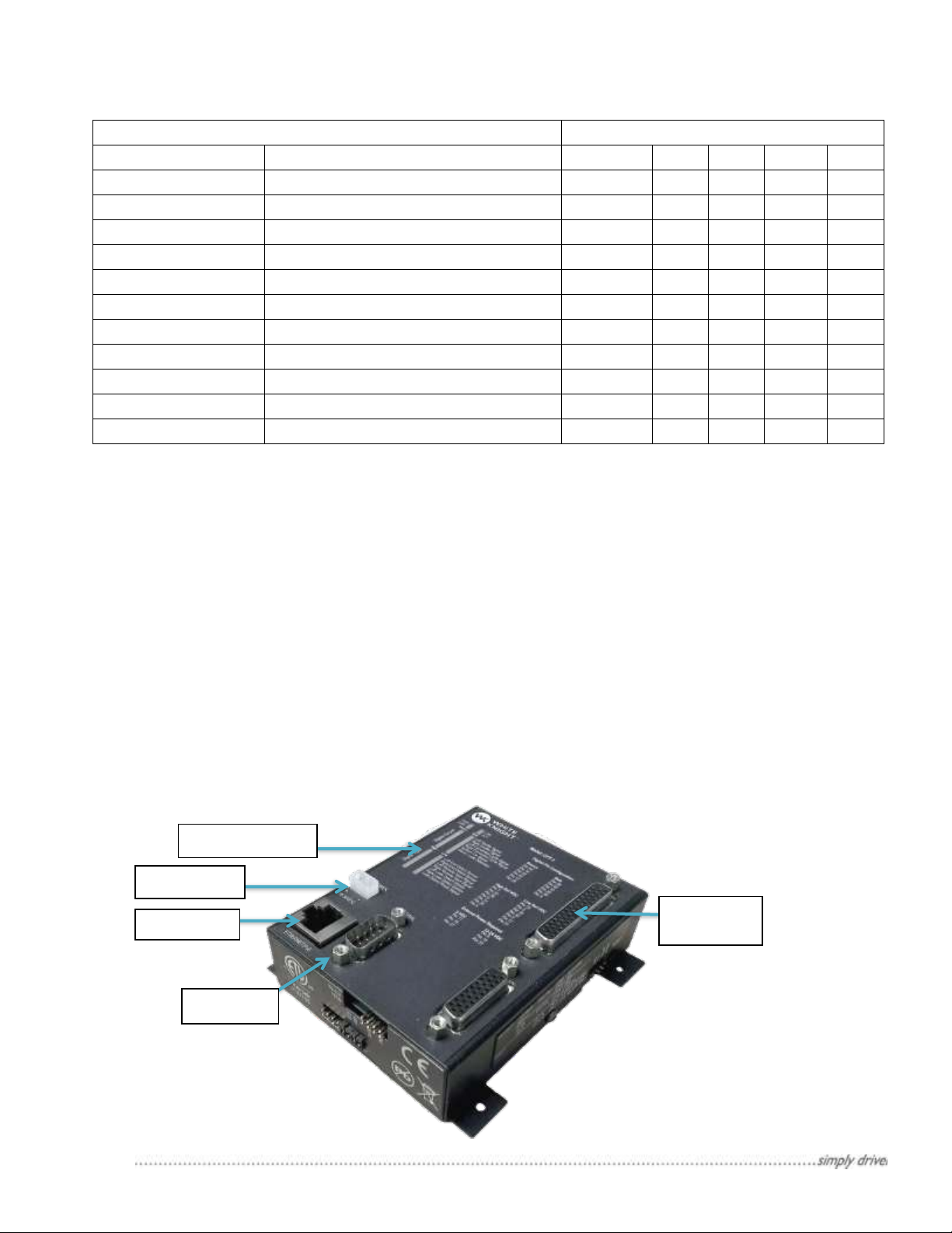
2 Parts List
Quantity of parts for each configuration callout
Part Numbers
Description
CPT-1
-W
-S
-Q
-P
8600-XX-0011
Translator Controller
1
8600-XX-0020
2 Pin Molex Connector
1
-1
8600-XX-0021
Molex Crip Pin
2
-2
8600-XX-0013
44 Pin Cable to Wire Leads
1
8600-XX-0018
Screw Terminal Breakout Board
1
14910-XX-0007
Controller Power Jumper Assembly
1 8600-XX-0061
44 Pin Quick Connection Board
1 8600-XX-0063
2 Pin Quick Connector
1
8600-XX-0064
4 Pin Quick Connector
16
10010-NY-0002
#4-40 ½” Thumb Screw
2 8600-XX-0015
24 VDC Power Supply
1
Power port
Ethernet
Indicator Lights
44-Pin
Connector
Figure 1: The CPT-1 Controller and communication ports.
RS-232
Part list by configuration options:
2.1 CPT-1 Cycle Rate Translator
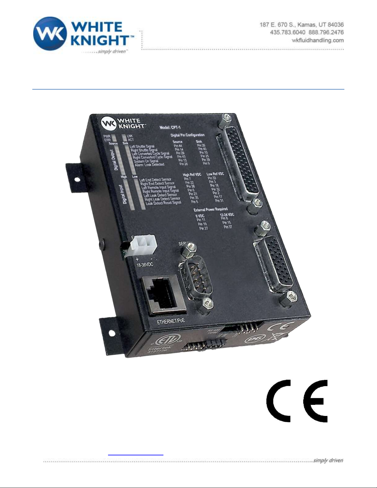
The CPT-1 control box is a small I/O communication device that converts the pump’s cycle rate to the cycle rate
that works with the tool’s algorithm. The control box has:
• 44-pin HD D-Sub Connector: Sends and receives digital signals.
• Indicator Lights: Show when each digital signal is active.
• Power Port: Takes 18-36 VDC input to power the controller.
• Ethernet Connector: This is used by the setup software to configure the controller.
• RS 232 serial communication: This is an alternate method of connecting to configure the controller.
Figure 1 shows an image of the WK CPT-1 controller with the above features labeled.
Manual Version 1.3.1 Manual Part# 18200-LM-0038
Page 5
2.2 Power Adapter with Crimp Pins
2.6 Quick Connect: 44-Pin HD D-Sub to Connectors
(Pin reference start at one from top as shown in image below)
2.4 Breakout Board: 44-Pin HD D-Sub
to Screw Terminal
2.3 Cable: 44-Pin HD D-Sub to Wire
2.5 Din Rail Power Supply
Power Connector:
• Pin 2: 24 VDC Power
Digital Output Connector:
Pin 1: 24 VDC Power
Type) Output
Digital Output Connector:
• Pin 1: 24 VDC Power
• Pin 2: Ground
• Pin 3: High Reference
(NPN Type) Input
• Pin 4: Low Reference
(PNP Type) Input
3 System Overview
•
• Pin 2: Ground
• Pin 3: Source (PNP
Type) Output
• Pin 4: Sink (NPN
• Pin 1: Ground
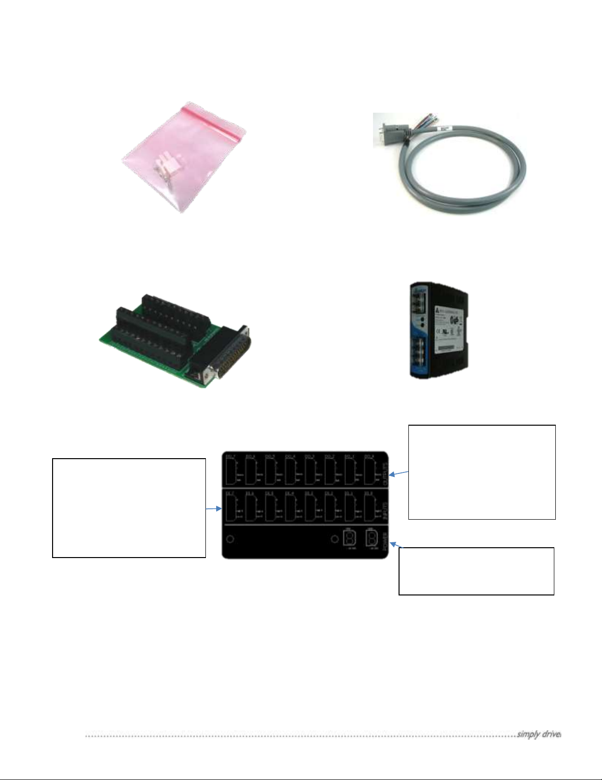
The CPT-1 has been designed to be an interface between the tool’s algorithm and a pneumatic pump. This interface
is needed when inserting an alternate pump into an existing tool; frequently the alternate pump will have a different
cycle rate than the previous pump which may cause the tool to alarm out.
The CPT-1 is able to operate the pneumatic pump at the cycle rate that is optimal for the pump. Then, the CPT-1
will scale the pump’s cycle rate by a factor set by the user and send the scaled cycle rate back to the tool. The CPT1 can be configured to work with any system setup.
Manual Version 1.3.1 Manual Part# 18200-LM-0038
Page 6
PoE EXT
The Tool sees the scaled
CPT-1.
The pump operates in
or End Stroke/Oscillate
WK CPT-
1
Tool
Algorithm
WK Pump
Scaled Cycle Rate Operation
Figure 2: Illustration of how the CPT-1 maintains two separate communication loops. The CPT-1
will run the pump and calculate its cycle rate (shown with black arrows). The CPT-1 will scale the
cycle rate and communicate the scaled cycle rate back to the tool (shown with gray arrows)
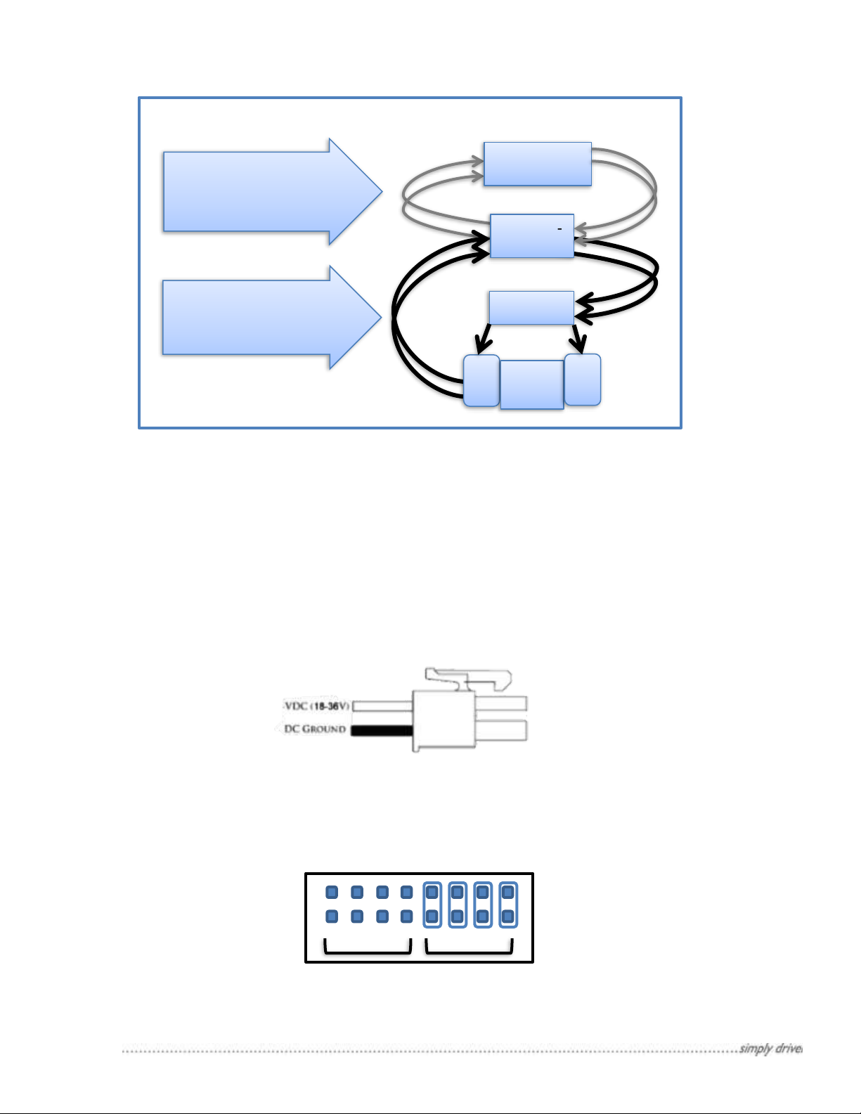
Figure 4: External power/Power over Ethernet selection jumpers.
Shown in figure is the default setup supporting external power
Figure 3: External power connector.
cycle rate from the WK
the current mode: End
Stroke Detect, Oscillate,
4 Power and Communication
4.1 Powering the CPT-1
There are two methods of powering the CPT-1: 18-36 VDC power connector and Power over Ethernet (PoE).
By default the CPT-1 is setup to use the external power adapter. Simply connect an appropriate DC power to the
connector as shown in Figure 3.
To setup PoE, find the jumpers labeled EXT and PoE on the bottom face of the controller. See figure 4. Move the
jumpers from EXT to PoE locations. POE can now be used.
Manual Version 1.3.1 Manual Part# 18200-LM-0038
Page 7

4.2 Ethernet Connection:
Pin Name
Pin #
Wire Color
Designation
Levels
Notes
Power:
Source
Outputs
15 Red/
Black Stripe
Power Source
12-24 VDC
The voltage input into these pins power
all of the source type outputs.
* The voltage input will equal the voltage
output from these ports.
27
Red/
White Stripe
Ground Reference
0 VDC
Power:
Sink Outputs
8
Green
Power Source
12-24 VDC
The voltage input into these pins will
power the sink type outputs.
11
Orange
Ground Reference
0 VDC
Power:
Input High
37
Violet/
Red Stripe
Reference Voltage
High
12-24 VDC
The Voltage input into this pin will be the
reference for all digital high inputs.
Power:
Input Low
19
Orange/
Black Stripe
Reference Voltage
Low
0 VDC
The Voltage input into this pin will be the
reference for all digital low inputs.
Table 1: Wire connections for powering the digital ports. All ports should be connected
The Ethernet connection is available for PC to CPT-1 communications. These communications are available for
setting up the software, and for on screen controls. After the controller has been setup the settings can be saved
and disconnected to be run as a standalone unit. The CPT-1 uses two industry standard Ethernet connection
protocols TCP/IP and UDP/IP, the controller will automatically respond in the format in which it is connected.
When connecting to the WK Controller to a local network. The WK Controller will look to the server to assign it an
IP address; this is supported on both DHCP and BOOT-P server protocols.
4.3 RS-232 Connection:
An RS-232 connection can be created through the 9 pin serial port on the box. When opening the software the
RS-232 port will show as a COM port and will give two baud rate options, 19200 and 115000. The default baud
rate is 115000, however the slower 19200 baud rate can be selected by placing a jumper on the connection
labeled 19.2 on the upper right side of the control box.
5 Digital I/O Setup
5.1 Power Digital Ports
The digital ports are not powered by the controller. An external power supply is required for the digital ports to be
active. Use Table 1 for digital port power connections.
* Note: When using the quick connection board simply connect power to one of the power ports, then power will
be distributed to all of the correct locations. See markings on the board for power and ground pins. The second
power port is to jumper power to the controller.
5.2 Digital Inputs:
Each digital input can be wired into either a high or low voltage reference see Table 2.
Manual Version 1.3.1 Manual Part# 18200-LM-0038
Page 8

Pin Name
Pin #
Wire Color
Designation
Levels
Note
Digital Input:
Remote Left
[DI_2]
36
Yellow/
Red Stripe
High VDC Reference
24 V = Not Active
0 V = Active
When one of these
connections becomes active,
the CPT-1 will turn on and start
controlling the pneumatic
pump. Disconnect the left and
right inputs from the shuttle
and connect these signals to
the appropriate high or low
voltage reference on the CPT-1.
18
Green/
Black Stripe
Low VDC Reference
0 V = Not Active
24 V = Active
Digital Input:
Remote Right
[DI_3]
6
Blue
High VDC Reference
24 V = Not Active
0 V = Active
32
Gray/
Red Stripe
Low VDC Reference
0 V = Not Active
24 V = Active
Digital Input:
End Detect Left
(Full Cycle Signal)
[DI_0]
7
Brown
High VDC Reference
24 V = Not Active
0 V = Active
The left end detect is used to
count each full cycle. If using a
shuttle-operated pump,
connect a pressure switch or
end detect sensor to the left
end detect signal.
If using a solenoid valve-
operated pump, connect both
the left and right end detect
sensors such that the signal is
active when the sensor is
triggered.
33
Light Green/
Red Stripe
Low VDC Reference
0 V = Not Active
24 V = Active
Digital Input:
End Detect Right
[DI_1]
22
Gray/
Black Stripe
High VDC Reference
24 V = Not Active
0 V = Active
3
Red
Low VDC Reference
0 V = Not Active
24 V = Active
Digital Input:
Leak Detect Left
[DI_4]
21
Brown/
Black Stripe
High VDC Reference
24 V = Not Active
0 V = Active
For systems that do not
support a leak detect function
to turn off the pump when
leaks are detected, leak detect
signals can be brought into
these digital inputs. When the
leak detect signal is active, the
CPT-1 will stop the pump and
wait for the reset signal before
the pump will restart.
2
White
Low VDC Reference
0 V = Not Active
24 V = Active
Digital Input:
Leak Detect Right
[DI_5]
35
Pink/
Red Stripe
High VDC Reference
24 V = Not Active
0 V = Active
17
Violet/
Black Stripe
Low VDC Reference
0 V = Not Active
24 V = Active
Digital Input:
Alarm Reset
[DI_6]
5
Violet
High VDC Reference
24 V = Not Active
0 V = Active
When alarms are enabled: leak
detect, or speed alarms it is
recommended that the alarm
reset signal is connected. This
can be wired into the tool or to
a physical button located near
the pump. f
31
Blue/
White Stripe
Low VDC Reference
0 V = Not Active
24 V = Active
Table 2: List of all digital input connections with a description of behaviors
Manual Version 1.3.1 Manual Part# 18200-LM-0038
Page 9

5.3 Digital Outputs:
Pin Name
Pin #
Wire Color/
Stripe
Designation
Levels
Note
Digital Output:
Left Solenoid
[DO_0]
26
Orange/
White Stripe
Sink
Relay Open = Not Active
Relay Closed = Active
The CPT-1 will turn
on the left and right
solenoid signals to
control a solenoid-
operated pump. If
using a shuttleoperated pump
these connections
are not required.
44
Light Green/
Green Stripe
Source
Relay Open = Not Active
Relay Closed = Active
Digital Output:
Right Solenoid
[DO_1]
40
Red/
Green Stripe
Sink
Relay Open = Not Active
Relay Closed = Active
14
White/
Black Stripe
Source
Relay Open = Not Active
Relay Closed = Active
Digital Output:
Left Translated
Cycle Rate
[DO_2]
10
Light Blue
Sink
Relay Open = Not Active
Relay Closed = Active
This is the output to
tell the tool about
the modified cycle
rate. If the tool is
only looking for one
signal indicating a
full cycle rate, only
connect one of these
to the tool.
Otherwise connect
both left and right to
the tool.
29
Brown/
White Stripe
Source
Relay Open = Not Active
Relay Closed = Active
Digital Output:
Right Translated
Cycle Rate
[DO_3]
25
Pink/
Black Stripe
Sink
Relay Open = Not Active
Relay Closed = Active
43
Light Blue/
Green Stripe
Source
Relay Open = Not Active
Relay Closed = Active
Digital Output:
System On
[DO_4]
39
Orange/
Green Stripe
Sink
Relay Open = Not Active
Relay Closed = Active
This is to indicate
that the system is
on. This input is
required when
operating a shuttle
pump. However this
can also be used as
verification that the
system is
operational.
13
Pink
Source
Relay Open = Not Active
Relay Closed = Active
Digital Output:
Leak Alarm
[DO_5]
9
Gray
Sink
Relay Open = Not Active
Relay Closed = Active
This output is to alert
the user that a leak
was detected.
28
Violet/
White Stripe
Source
Relay Open = Not Active
Relay Closed = Active
Digital Output:
Over Speed
Alarm
[DO_6]
24
Light Green/
Black Stripe
Sink
Relay Open = Not Active
Relay Closed = Active
This output is to alert
the user that the
pump was operating
faster than the set
threshold
42
Brown/
Green Stripe
Source
Relay Open = Not Active
Relay Closed = Active
Digital Output:
Under Speed
Alarm
[DO_7]
38
Gray/
Green Stripe
Sink
Relay Open = Not Active
Relay Closed = Active
This output is to alert
the user that the
pump was operating
slower than the set
threshold
12
Light Green
Source
Relay Open = Not Active
Relay Closed = Active
Table 3: List of digital output wiring with designations
The CPT-1 sends out signals to control or be read by other devices. There are two types of digital outputs, voltage
source or a voltage sink. The CPT-1 will turn on both corresponding voltage source and sink when it turns on an
output. Generally, components that may have a higher current draw should be connected to the voltage s ink.
Manual Version 1.3.1 Manual Part# 18200-LM-0038
Page 10

Tool Communication
Pump Type
Leak Detection**
End
Stroke
Detection
On-Off
with Cycle
Counter
Cycle
Counter
Only
Solenoid
Pump
Shuttle
Pump
Tool
CPT-1
Digital Input
Remote Left
From Tool
From Tool
Hard
Wire
Active
Remote Right
From Tool
End Detect Left
From
Pump
From
Pump
End Detect Right
From
Pump
Leak Detect Left
From
Pump
Leak Detect Right
From
Pump
Leak Reset
From
Physical
Button or
Tool
Digital Output
Left Solenoid
To
Solenoid
Right Solenoid
To
Solenoid
Left Translated Cycle Rate
To Tool
To Tool
To Tool
Right Translated Cycle Rate
To Tool
System On
To Air
Valve*
Leak Alarm
To Tool
or Alarm
Over Speed Alarm
(Optional)
To Tool
or Alarm
To Tool
or Alarm
Over Speed Alarm
(Optional)
To Tool
or Alarm
To Tool
or Alarm
Table 4: Wiring Selection table
5.4 Wiring Configurations
The CPT-1 works within a variety of configurations. Use Table 4 to learn which wiring connections should be
connected when setting up the CPT-1. These connections have been divided into 3 sections that need to be
selected.
• Tool Communications – The tool will need to send a signal to tell the CPT-1 to turn on-off and will need
to receive a signal from the CPT-1 for the cycle rate.
• Pump Type - The CPT-1 will send signals to open valves to operate the selected pump, and expects to
receive end detect signals from the pump.
• Leak Detection – In the case where the tool already handles leak errors from a pump, there is no need to
connect leak detection to the CPT-1; however, if the tool does not handle leak detection, this can be wired
into the CPT-1.
Select one column from each section that matches the system configuration, and then use the rows in the table to
determine how the system should be wired.
Manual Version 1.3.1 Manual Part# 18200-LM-0038
Page 11

* In the case where the tool varies the air pressure to a shuttle-operated pump, there is no need to connect the
CPT-1 Connected via Ethernet
CPT-1 Connected via RS-232
Figure 5: Connections Window
system on signal to an additional air valve.
** See Pump manual for wire leak detection.
6 PC to CPT-1 Communication:
6.1 Ethernet Connection:
An Ethernet connection is only needed for using the CPT-1 setup software. After the controller has been setup, the
settings can be saved and disconnected to be run as a standalone unit. The CPT-1 uses two industry standard
Ethernet connections TCP/IP and UDP/IP the controller will automatically respond in the format to which it is
connected. When connecting the CPT-1 to a local network, it will look to the server to assign it an IP address. This
is supported on both DHCP and BOOT-P server protocols.
6.2 RS-232 Connection:
An RS-232 connection can be created through the 9-pin serial port on the box. When opening the software, the
RS-232 port will show as a COM port and will give two baud rate options, 19200 and 115000. The default baud
rate is 115000, but the slower 19200 baud rate can be selected by placing a jumper on the connection labeled
19.2 on the upper left side of the control box.
7 Software Setup:
7.1 Installation:
Download the CPT-1 setup software at wkfluidhandling.com/cpt-1. Run the installers by double-clicking on the
installer executable (.exe) file, and follow the on screen prompts. Software requires Windows XP or newer version
of Windows.
7.2 Using the Software:
1. Open “WK Cycle Rate Translator.exe”.
2. Wait for the connections window to show. If you have a CPT-1 connected to the computer via RS-232 or to
the network via Ethernet, it will show in the connections window. See Figure 5 for an image of the
connections window.
Manual Version 1.3.1 Manual Part# 18200-LM-0038
Page 12

3. Select your controller and click “Connect”. (If the controller does not show, you can click “Cancel” and
Figure 6: Controls Window
proceed to the next screen where you can try connecting again.)
4. Wait for the Controls window to show. See Figure 6 for screen shot of controls window.
5. Set the desired controls parameters. See section 7.3 for more information about individual parameters.
6. When done, click “Save Defaults”. Note: if the settings are not saved, new settings will be lost when the
controller restarts.
7.3 Software Inputs:
Operation Mode: This controller can control the pump in three ways. To change between operation modes, move
the knob to the desired operation mode.
• Simulation Mode - Calibration mode runs the pump as a simple timer. Simulation mode has two functions:
1. Fiber-optic end stroke detection: To calibrate the fiber-optic sensors, set a slow cycle rate
Manual Version 1.3.1 Manual Part# 18200-LM-0038
(Recommended settings 16 CPM at 20-25 PSI). Then, turn on Simulation mode, and calibrate the
Page 13

fiber-optic sensors. After the fiber-optic sensors have been calibrated, switch the operation mode
out of Simulation mode.
2. System experimentation: When no pump is connected to the CPT-1 simulation mode can be used
to simulate how the system would operate if the pump were running at a set speed. Simulation
mode is ideal for testing that the connections are wired correctly, and for verifying how the tool will
react to different cycle rates without actually swapping out different pumps.
Warning: Simulation mode should never be used for long term operation of a pump. This will result
in premature damage to the pump.
• End Stroke Mode – End Stroke mode sends out a signal to open a valve that will cause one side of the
pump to pressurize and will wait for an end of stroke signal before switching to the other side. End Stroke
mode is recommended for applications where cycle rates may fluctuate due to variance in air supply
pressure. When operating a shuttle pump, it is required to use End Stroke mode.
• End Stroke/Timer – End Stroke/Timer mode sends out a signal to open a valve that will cause one side of
the pump to pressurize and when either the cycle timer or the end stroke is detected then the pressure will
switch to the other side. This is a specialized operation mode that is ideal for systems that expect the set
cycle rate to occur. This mode will also help protect the pump if an end detect sensor fails. This mode is
not for shuttle-operated pumps.
Cycle Rate: The cycle rate sets the default cycle rate. When the system turns on, it will start up with the default
cycle rate, and if the operation mode is set to End Stroke/Timer mode, this cycle rate will be forced as the slowest
cycle rate allowed by the system.
Scale Value: The scale value changes the speed of the converted signal back to the tool. The number represents
the ratio [Converted Cycle Rate] / [Actual Cycle Rate], thus if the scale is greater than one, the converted cycle rate
will be faster than the actual cycle rate. If the scale is less than one, the emulated cycle rate will be slower than the
actual cycle rate.
Output Percent: The output percent changes the duration of the converted signal as a percent of its duration. For
example if the signal should stay on until the signal from the opposite side turns on, set the output percent to 100%,
or if the signal should turn off shortly after turning on, set the percentage to a smaller value. Some experimentation
may be necessary to determine what output duration the tool’s algorithm is expecting.
Off Delay: The CPT-1 expects either the right or left remote signal from the tool to be on. In some cases there may
be a delay between the signal switching. The off delay will keep the system on for a set time without any signal
being sent. The default setting is one second, but can be changed from the user interface.
Dual Detect Mode: For the majority of pumps this mode should be turned off. This mode should only be turned on
in two cases:
1. A single probe dual detect pump is to be operated. In this case it is recommended that the CPT-1’s
operation mode also be set to End Stroke/Timer mode; this is recommended because it will prevent the
pump from getting out of sync in its oscillations when the pump is at dead head. Thus it is also
recommended that the cycle rate variable be set to a slower than the normal operation cycle rate so that
timer doesn’t affect normal operation.
2. A pressure switch is being used for end of stroke sensing where a double signal is being detected.
A double signal may be seen if the pressure switch is connected to an exhaust port. In this case the dual
detect mode will only count every other signal as an end of cycle signal.
Leak Alarm: When connecting leak detect through the CPT-1, the leak alarm will light up when leaks are detected
and the pump will turn off. In order to turn the pump back on, the leak reset needs to be sent.
Over Speed/Under Speed Alarms: These alarms can be configured in the alarm settings. The following describe
the alarm settings that can be configured.
• Enabled – If alarm is enabled then the alarm is allowed to occur, if disabled then the alarm will never occur.
• Threshold – The cycle rate that if passed the alarm will occur.
Manual Version 1.3.1 Manual Part# 18200-LM-0038
Page 14

• On Delay – The duration in milliseconds that the over speed/under speed alarm condition is allowed to be
true before the alarm actually occurs. (This might be needed for start-up conditions)
• Auto Stop – When the alarm occurs and auto stop is enabled, then the pump will be shut down until the
reset signal has been received.
• Auto Recover – When an alarm occurs and the cycle rate returns to an acceptable operation the alarm will
turn itself off. Note: this feature will not work if the auto stop is enabled.
Save Defaults: Saving the defaults will tell the controller that the current settings are to be used as the defaults
when there are power outages. It is recommended to save the defaults after modifying any settings. If the defaults
are not saved, the controller will lose all changes made to the settings.
Reset: This action clears the alarms and enabled the pump to startup from normally. This action can be performed
in the software interface, or using the digital alarm reset button.
Connect/Disconnect: If connection was lost or when it is desired to connect to a different control box, use the
Connect and Disconnect buttons. The software can only be connected to one device at a time, so when switching
communications from one controller to another, the user should first disconnect from the current connection and
then connect to the new connection.
Command Line Entry: This tool enables specific commands to be issued to the controller and check the response
sent back from the controller.
Set IP Address: By default the control box is set to look for an IP address to be set from the DHCP network.
However, this tool can be used to force an IP address to the box independent of the network.
Update Firmware: If there is a discrepancy in the software version and the controller firmware version, then this
tool can be used to update the controller to the compatible version.
8 Troubleshooting Q & A:
8.1 Issues connecting to CPT-1 via Ethernet:
• Check that all wires are connected correctly.
• Check that the network is assigning an IP Address. (Contact system administrator for help).
• Press the Reset button on the controller, wait a moment for system restart, and try connecting again.
• If still unable to connect, contact White Knight at Tech.Support@wkfluidhandling.com
8.2 Issues Connecting to CPT-1 via RS-232:
• Ensure wires are connected correctly.
• Ensure serial port uses RS-232 connection protocol.
• Go to the device manager on your computer.
o Verify that your computer assigned a COM port for the device.
o Verify that the COM port is set to a baud rate of 115000
• Try power cycling the control box by pressing the Reset button on the control box.
• If still unable to connect, contact White Knight at Tech.Support@wkfluidhandling.com
Manual Version 1.3.1 Manual Part# 18200-LM-0038
Page 15

9 Appendix 1: Complete Wiring Guide Table
Pin Name
[Quick Connect Port]
Pin # Wire
Color/Stripe
Designation
Levels
Note
Power:
Source Outputs
15
Red/Black
Power Source
12-24 VDC
The voltage input into these
pins will be the voltage output
for all Source type output pins.
27
Red/White
Ground Reference
0 VDC
Power:
Sink Outputs
8
Green
Power Source
12-24 VDC
The voltage input into these
pins will power the sink type
output pins.
11
Orange
Ground Reference
0 VDC
Power:
Input High
37
Violet/Red
Reference Voltage
High
12-24 VDC
The voltage input into this pin
will be the reference for all
digital high inputs.
Power:
Input Low
19
Orange/Black
Reference Voltage
Low
0 VDC
The voltage input into this pin
will be the reference for all
digital low inputs.
Digital Input:
Remote Left
[DI_2]
36
Yellow/Red
Reference High VDC
24 V = Not Active
0 V = Active
When one of these
connections becomes active,
the CPT-1 will turn on and start
controlling the pneumatic
pump. Disconnect the left and
right inputs from the shuttle
and connect these signals to
the appropriate high or low
voltage reference on the CPT-
1.
18
Green/Black
Reference Low VDC
0 V = Not Active
24 V = Active
Digital Input:
Remote Right
[DI_3]
6
Blue
Reference High VDC
24 V = Not Active
0 V = Active
32
Gray/Red
Reference Low VDC
0 V = Not Active
24 V = Active
Digital Input:
End Detect Left, or
Full Cycle Signal
[DI_0]
7
Brown
Reference High VDC
24 V = Not Active
0 V = Active
The left end detect is used to
count each full cycle. If using a
shuttle operated pump,
connect a pressure switch or
end detect sensor to the left
end detect signal.
If using a solenoid valve-
operated pump, connect both
the left and right end detect
sensors such that the signal is
active when the sensor is
triggered.
33
Light Green/Red
Reference Low VDC
0 V = Not Active
24 V = Active
Digital Input:
End Detect Right
[DI_1]
22
Gray/Black
Reference High VDC
24 V = Not Active
0 V = Active
3
Red
Reference Low VDC
0 V = Not Active
24 V = Active
Digital Input:
Leak Detect Left
[DI_4]
21
Brown/Black
Reference High VDC
24 V = Not Active
0 V = Active
For systems that do not
support a leak detect function
to turn off the pump when
leaks are detected, leak detect
signals can be brought into
these digital inputs. When the
leak detect signal is active, the
CPT-1 will stop the pump and
wait for the reset signal before
the pump will restart.
2
White
Reference Low VDC
0 V = Not Active
24 V = Active
Digital Input:
Leak Detect Right
[DI_5]
35
Pink/Red
Reference High VDC
24 V = Not Active
0 V = Active
17
Violet/Black
Reference Low VDC
0 V = Not Active
24 V = Active
Digital Input:
Leak Reset
[DI_6]
5
Violet
Reference High VDC
24 V = Not Active
0 V = Active
When using a leak detect
sensor through the CPT-1, it is
required to connect this leak
detect signal. This can be wired
into the tool or to a physical
button located near the pump.
31
Blue/White
Reference Low VDC
0 V = Not Active
24 V = Active
Manual Version 1.3.1 Manual Part# 18200-LM-0038
Page 16

Digital Output:
Left Solenoid
[DO_0]
26
Orange/White
Sink: Connect To
ground when closed
Relay Open = Not Active
Relay Closed = Active
The CPT-1 will turn on the left
and right solenoid signals to
control a solenoid operated
pump. If using a shuttle
operated pump, these
connections are not required.
44
Light
Green/Green
Source: Connect to
power when closed
Relay Open = Not Active
Relay Closed = Active
Digital Output:
Right Solenoid
[DO_1]
40
Red/Green
Sink: Connect To
ground when closed
Relay Open = Not Active
Relay Closed = Active
14
White/Black
Source: Connect to
power when closed
Relay Open = Not Active
Relay Closed = Active
Digital Output:
Left Translated
Cycle Rate
[DO_2]
10
Light Blue
Sink: Connect To
ground when closed
Relay Open = Not Active
Relay Closed = Active
This output tells the tool about
the modified cycle rate. If the
tool is only looking for one
signal indicating a full cycle
rate, only connect one of these
to the tool. Otherwise connect
both left and right to the tool.
29
Brown/White
Source: Connect to
power when closed
Relay Open = Not Active
Relay Closed = Active
Digital Output:
Right Translated
Cycle Rate
[DO_3]
25
Pink/Black
Sink: Connect To
ground when closed
Relay Open = Not Active
Relay Closed = Active
43
Light Blue/Green
Source: Connect to
power when closed
Relay Open = Not Active
Relay Closed = Active
Digital Output:
System On
[DO_4]
39
Orange/Green
Sink: Connect To
ground when closed
Relay Open = Not Active
Relay Closed = Active
This is to indicate that the
system is on. This input is
required when operating a
shuttle pump. However, this
can also be used as verification
that the system is operational.
13
Pink
Source: Connect to
power when closed
Relay Open = Not Active
Relay Closed = Active
Digital Output:
Leak Alarm
[DO_5]
9
Gray
Sink: Connect To
ground when closed
Relay Open = Not Active
Relay Closed = Active
This output is to alert the user
that a leak was detected.
28
Violet/White
Source: Connect to
power when closed
Relay Open = Not Active
Relay Closed = Active
Digital Output:
Under Speed
Alarm
[DO_7]
38
Gray/
Green Stripe
Sink
Relay Open = Not Active
Relay Closed = Active
This output is to alert the user
that the pump was operating
slower than the set threshold
12
Light Green
Source
Relay Open = Not Active
Relay Closed = Active
Digital Output:
Over Speed Alarm
[DO_6]
24
Light Green/
Black Stripe
Sink
Relay Open = Not Active
Relay Closed = Active
This output is to alert the user
that the pump was operating
faster than the set threshold
42
Brown/
Green Stripe
Source
Relay Open = Not Active
Relay Closed = Active
Figure 7: Pin out diagram for 44-pin connector
Manual Version 1.3.1 Manual Part# 18200-LM-0038
Page 17

Controller Label
Manual Version 1.3.1 Manual Part# 18200-LM-0038
Page 18

10 Appendix 2: Dimensional Diagrams
Manual Version 1.3.1 Manual Part# 18200-LM-0038
Page 19

11 Ordering Instructions
CPT-1 (Cycle Rate Translator) Ordering Instructions
- - -
W QS
White Knight Fluid Handling, Inc.
435-783-6040
Optional Configurations
= 44 male pin to 1-
Meter Wire Lead Cable
W①P
②
CPT-1
To configure your Cycle Rate Translator with different connection methods, a power supply or request a specific revision level,
please select options from the appropriate additional options (1-3).
www.wkfluidhandling.com
③ Revision Level : Contact factory for copy exact code activation information.
Rev
③
= 44 male pin to Screw
Terminals
① Connection Method
② Power Supply
P
= 24V/60W Power
Supply
Required
Configurations
Additional
Options
= Quick Connect Plugs
(Registered by Galil Motion Control, Inc.)
Manual Version 1.3.1 Manual Part# 18200-LM-0038
Page 20

Manual Version 1.3.1 Manual Part# 18200-LM-0038
 Loading...