

Page 1
CPC-1: Closed Loop Controller Manual
Manual available online at wkfluidhandling.com
Manual Version 1.0.1 Manual Part# 18200-LM-0037
Page 2

Manual content and data are subject to change without notification. The most recent version of the manual can be found online at:
http://wkfluidhandling.com/owners-manuals
Page Left Intentionally Blank
Manual version 1.0.1
Page 3

Table of Contents
1. System Recommendations .................................................................................................................................2
1.1 Precautions .......................................................................................................................................................2
1.2 System Environment Recommendations/Requirements ..................................................................................2
1.3 Installation Advantages .....................................................................................................................................2
1.4 Getting Started ..................................................................................................................................................3
2. Parts List .............................................................................................................................................................4
2.1 CPC-1 Closed Loop Controller .........................................................................................................................4
2.2 Power Adapter with Crimp Pins ........................................................................................................................5
2.3 Cable: 26 Pin & 44 HD D-Sub to Wire Leads ...................................................................................................5
2.4 Breakout Board: 26 Pin HD D-Sub to Screw Terminals ...................................................................................5
2.5 Din Rail Power Supply ......................................................................................................................................5
2.6 Quick connect boards. Using field wire-able connectors to make connections easier. ....................................5
3. Non-Stock Items Needed....................................................................................................................................6
3.1 I/P Air Regulator ................................................................................................................................................6
3.2 Pressure Transducer ........................................................................................................................................6
3.3 Flow Meter ........................................................................................................................................................6
4 System Overview .....................................................................................................................................................6
5 Setup .......................................................................................................................................................................7
5.1 Plumbing the system .........................................................................................................................................7
5.2 Supply Air Pressure ..........................................................................................................................................7
5.3 Wiring Setup ......................................................................................................................................................7
5.3.1 Powering the CPC-1 ......................................................................................................................................8
5.3.2 Digital Connections ........................................................................................................................................8
5.3.2.1 Power Digital Ports: ....................................................................................................................................8
5.3.2.2 Digital Input Ports ........................................................................................................................................9
5.3.2.3 Digital Output Ports .................................................................................................................................. 10
5.3.3 Analog Connections .................................................................................................................................... 11
5.3.3.1 Common Ground ..................................................................................................................................... 11
5.3.3.2 Supplemental low power supply .............................................................................................................. 12
5.3.3.3 Analog Inputs ........................................................................................................................................... 12
5.3.3.4 Analog Outputs ........................................................................................................................................ 13
5.3.3.5 Wiring Summary ...................................................................................................................................... 13
6 PC to CPC-1 Communication: .............................................................................................................................. 14
6.1 Ethernet Connection: ..................................................................................................................................... 14
6.2 RS-232 Connection: ....................................................................................................................................... 14
7 Desktop Software ................................................................................................................................................. 14
7.1 Installation ...................................................................................................................................................... 14
Manual Version 1.0.2
Page 4

7.2 Using the software ......................................................................................................................................... 14
7.2.1 Controls Window ......................................................................................................................................... 15
7.2.1.1 Sensor Gauges ........................................................................................................................................ 15
7.2.1.2 System Alarms ......................................................................................................................................... 16
7.2.1.3 Operation Mode setup ............................................................................................................................. 16
7.2.1.4 Additional Menu Items ............................................................................................................................. 16
7.2.2 Setup Window ............................................................................................................................................. 18
7.2.2.1 Process Settings ...................................................................................................................................... 18
7.2.2.2 Analog I/O Settings .................................................................................................................................. 19
7.2.2.3 Digital I/O Settings ................................................................................................................................... 20
7.2.3 Advanced Window ...................................................................................................................................... 21
7.2.3.1 Terminal Tab ............................................................................................................................................ 21
7.2.3.2 Customize PID Gains Tab ....................................................................................................................... 21
7.2.3.3 Configurations Tab ................................................................................................................................... 22
8 Standalone Operation ........................................................................................................................................... 22
8.1 Using Digital Communication ......................................................................................................................... 23
8.1.1 Operation Mode .......................................................................................................................................... 23
8.1.2 Set Point Modification ................................................................................................................................. 23
8.1.3 Leak Detect Reset ...................................................................................................................................... 23
9 Troubleshooting .................................................................................................................................................... 24
9.1 Issues connecting to CPC-1 via Ethernet, preform the actions below ........................................................... 24
9.2 Issues Connecting to CPC-1 via RS-232, preform the actions below ........................................................... 24
9.3 Issues with Stable Flow ................................................................................................................................. 24
10 Appendix 1: 44 Pin D-Sub Connection Table ..................................................................................................... 26
11 Appendix 2: 26 Pin HD D-Sub Connection Table ............................................................................................... 29
12 Appendix 3: Dimensional Drawings .................................................................................................................... 32
13 Ordering Instructions .......................................................................................................................................... 33
1 Manual version 1.0.2
Page 5

1. System Recommendations
DO NOT OPEN CONTROL BOX
Do not open the control box. White Knight is not responsible for any damage caused by opening the
Control Box.
Environmental Temperature
This product is rated to withstand environmental temperatures up to 70°C.
Grounding
All electrical components must be grounded to minimize risk of sparks. Follow proper procedures for
grounding all products in the system.
Flow and Pressure Monitoring
The CPC-1 is able to take in both a pressure transducer and flow meter signals at the same time. While
troubleshooting purposes.
Non-stock Items Needed
The Closed Loop Control system makes use of several off the shelf items that White Knight does not
product. See section 3 of this manual for detailed descriptions of needed parts.
System Limitations
The CPC controls the parameters of the system based off of the selected pump and would not protect
system components that are not rated as high as the pump the controller is programmed to control.
Flow and Pressure
White Knight recommends the installation of a pressure transducer as well as a flow meter to allow for
without any addition or change to system components.
1.1 Precautions
supply. There is a large variety of products and suppliers and the end user may obtain their preferred
1.2 System Environment Recommendations/Requirements
increased monitoring as well as the ability to switch between flow and pressure control within a system
1.3 Installation Advantages
only one is needed for the desired control process, the other can be input for monitoring and
2 Manual version 1.0.2
Page 6

1.4 Getting Started
Installing the CPC-1 for the first time it is recommended that you follow these steps:
1) Verify that you received all of the components that you ordered. Note: cables and breakout board for the
controller are options that can be selected at the time of purchase.
2) Check that you have a compatible power supply to power the controller. See Section 5.3.1
3) Check that you have a compatible communication cable for setting up the controller. See Section 6
4) Download the setup software from www.wkfluidhandling.com/cpc-1.
5) Verify that your computer is able to connect to the controller.
a) Power up the controller with correct power source
b) Connect the communication cable correctly. (Ethernet cables should go from the controller to a network
switch, not your PC)
c) Install and launch the Smart Control Software.
d) The connections dialog should appear at launch. Verify that your controller appears on the list and click
the connect button. See Section 7.2
e) Once connectivity is verified disconnect from the software, and disconnect power and communication
cable.
6) Install CPC-1 in the desired location.
7) Connect 44 pin and 26 pin connectors and use the wiring guide in Section 5.3.2 and 5.3.3 to connect system.
8) Connect to controller (same as before) and configure the CPC-1 settings to match your system needs.
3 Manual version 1.0.2
Page 7
2. Parts List
#
Description
Part Number
Component
2.1
Control Box
CPC-1
Standard
Power Adapter With Crimp Pins
Standard
2.4
44 Pin HD D-Sub to Screw Terminals
8600-XX-0018
Optional
2.3
44 Pin HD D-Sub to wire leads Cable 1-Meter
8600-XX-0013
Optional
2.4
26 Pin HD D-Sub to Screw Terminals
8600-XX-0019
Optional
2.3
26 Pin HD D-Sub to wire leads Cable 1-Meter
8600-XX-0014
Optional
2.5
24 Volt Power Supply - 60 Watt
8600-XX-0015
Optional
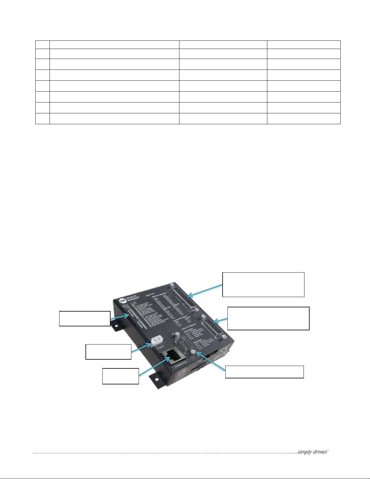
Power port
Ethernet
Indicator Lights
44-Pin Connector for
26-Pin Connector for
Analog Communications
RS-232 Serial Port
Figure 1: The CPC-1 Controller and its communication ports.
* For size of items in parts list see section 12
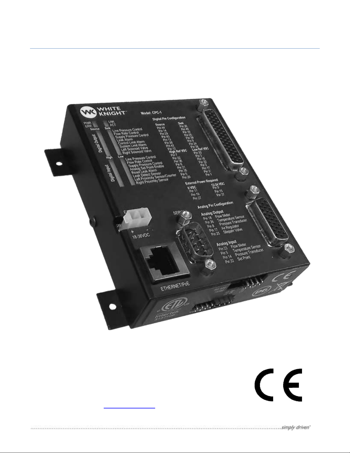
2.1 CPC-1 Closed Loop Controller
The CPC-1 control box is a small I/O communication device that controls the supply air pressure to the pump in
order to maintain either flow or pressure changes. The control box has:
• 44-pin HD D-Sub Connector: Sends and receives digital signals.
• Indicator Lights: Show when each digital signal is active.
• 26-pin HD D-Sub Connector: Sends and receives analog signals.
• Power Port: Takes 18-36 VDC input to power the controller.
• Ethernet Connector: Can be used by the setup software to configure the controller.
• RS 232 serial communication: Can be used by the setup software to configure the controller.
Figure 1 shows an image of the CPC-1 controller. Note: the production version will come with a din rail mount,
where the beta version does not.
Digital Communications
4 Manual version 1.0.2
Page 8
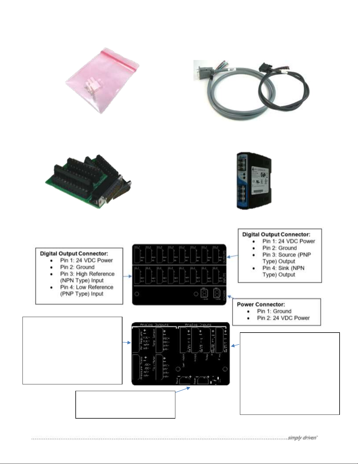
2.2 Power Adapter with Crimp Pins
2.3 Cable: 26 Pin & 44 HD D-Sub to
2.4 Breakout Board: 26 Pin HD D-Sub
to Screw Terminals
2.5 Din Rail Power Supply
Analog Output Connectors:
Analog Input Connectors:
different pinouts.
Power Connectors:
• Pin 2: 24 VDC Power
2.6 Quick connect boards. Using field wire-able connectors to make connections easier.
• Pin 1: 24 VDC Power
• Pin 2: Ground
• Pin 3: Voltage Output
• Pin 4: Voltage Reference
• Pin 5: Current Output
• Pin 6: Current Reference
• Pin 1: Ground
• Pin 1: 24 VDC Power
• Pin 2: Ground
• Pin 3: Analog Input
• Pin 4: Voltage Reference
• Pin 5 & 6: If Input is a
current input jumper two
pins together.
Note: Temp Connector has
5 Manual version 1.0.2
Page 9

3. Non-Stock Items Needed
The Closed Loop Control system makes use of several off the shelf items that White Knight does not supply.
There is a large variety of products and suppliers so the end user may obtain their preferred products. Below is a
brief description of these components and the CPC-1 interface requirements.
3.1 I/P Air Regulator
An electronic proportional air regulator is required for the closed loop control system. Minimum specifications for
I/P air regulator are:
• Supports a pressure range from 0 to 100 PSI.
• Supports air flow requirement for selected WK pump. (See pump’s manual)
• Ability to set pressure using analog signal*.
* The CPC-1 only supports analog voltage analog outputs (0-5 VDC, 0-10 VDC), if an analog current signal (0-20
mA or 4-20mA) is required then the 4-20 mA Expansion Board or a signal conditioner is required.
3.2 Pressure Transducer
A pressure transducer is only required for systems in which pressure control is desired. However, for systems that
are using flow control a pressure transducer can be added into the system for system monitoring. The minimum
specifications for the pressure transducer are:
• Support the full range of system pressures up to 100 PSI
• Output pressure reading via analog signal*
* If the pressure transducer outputs an analog current signal then a 500 ohms resistor or smaller can be
connected between the signal and ground connections to convert the signal to a voltage signal. (The 420 mA Analog Expansion Board will already have a 250 ohm resistor correctly placed for this conversion)
3.3 Flow Meter
A flow meter is only required for systems in which flow control is desired. However, for systems that are using
pressure control a flow meter can be added into the system for system monitoring. The minimum specifications
for the flow meter are:
• Support the full range of system flows.
• Output flow reading via analog signal*
* If the flow meter outputs an analog current signal then a 500 ohms resistor or smaller can be connected
between the signal and ground connections to convert the signal to a voltage signal. (The 4-20 mA
Analog Expansion Board will already have a 250 ohm resistor correctly placed for this conversion)
4 System Overview
Closed loop control is a self-monitoring system that will maintain one process variable independent of changes in
the system. The CPC-1 closed loop controller has two different control modes:
Pressure Control – Uses feedback from a pressure transducer to maintain a set line pressure at a
desired point in the system. Pressure transducers are able to detect small changes in the system with little to no
time delay. Thus a pressure controlled system is more responsive to changes in the system, such as a point of
use with multiple valves that open and close frequently. A pressure control system can also be used to maintain
flow in the system where a fixed pressure through a fixed orifice can result in a steady flow.
Flow Control – Uses feedback from a flow meter to maintain a desired flow rate in the system. Flow
meters generally use a rolling average to detect flow in the system, which results in a less responsive sensor.
6 Manual version 1.0.2
Page 10
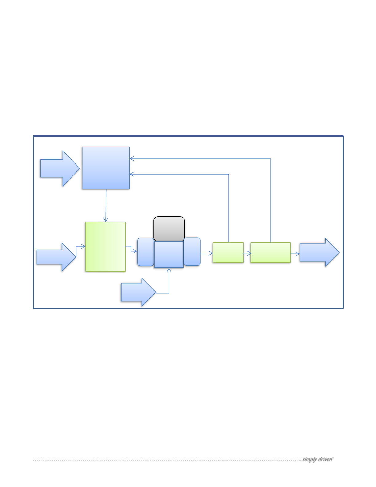
Thus a flow controlled system is slow to respond to changes in the system. Flow control processes are frequently
Fluid to
PLC
Commands
Pressure
Transducer
Air
Regulator
Pulse
Dampener
WK Pump
Supply Air
Fluid to
Flow
Meter
CPC-1
Analog Flow Signal
Analog Pressure Signal
Figure 2: Control Process diagram where elements shown in green can be obtained from a
third-party distributer. Note: Depending on which model of I/P Air regulator is selected they
may be two separate components or they may be one consolidated unit.
used in plating or mixing operations where the flow doesn’t change, but where the filter may clog over time. The
flow control will slowly adjust the pressure as flow restrictions build up in a filter. Using flow control can lengthen
the usable life of a filter because the control will maintain the correct flow.
The CPC-1 is able to take in both a pressure transducer and flow meter signals at the same time. While only one
is needed for the desired control process, the other can be input for monitoring and troubleshooting purposes.
Note: White Knight does not supply pressure transducers or flow meters. See Non-Stock Items Needed for more
information about selecting a pressure transducer and flow meter.
System
Pump
5 Setup
5.1 Plumbing the system
Assemble the system plumbing as normal and include the correct sensors that are required for the closed loop
control process; a pressure transducer for pressure controlled systems or a flow meter for flow controlled
processes. These sensors should be placed in the critical path close to the point of use. In some cases it may be
advantageous to add both sensors into the system; this will allow additional flexibility for implementing closed loop
control allowing the end operator to monitor both sensors, and have the ability to switch control methods.
5.2 Supply Air Pressure
The supply air going into the closed loop control system should be set to 100 PSI. The supply air is then directed
into the air regulator. The air regulator controls how much air is supplied to the pump and pulse dampener. See
Figure 2 for illustration of the air flow.
5.3 Wiring Setup
The CPC-1 has the following on device connections interfaces:
7 Manual version 1.0.2
Page 11
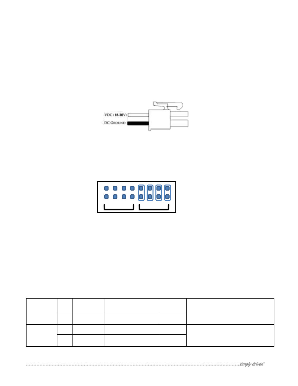
• 18-36 VDC Power Connector
Pin Name
Pin #
Wire Color
Designation
Levels
Notes
Power:
Source
Outputs
15
Red/
Black Stripe
Power Source
12-24 VDC
The voltage input into these pins power
all of the source type outputs.
* The voltage input will equal the voltage
output from these ports.
27
Red/
White Stripe
Ground Reference
0 VDC
Power:
Sink Outputs
8
Green
Power Source
12-24 VDC
The voltage input into these pins will
power the sink type outputs.
11
Orange
Ground Reference
0 VDC
Figure 3: External Power Connector
Figure 4: External power / Power over Ethernet Selection jumpers.
PoE EXT
Default setup supporting external power shown.
Table 1: Wire connections for powering the digital ports. All ports
should be connected.
• Ethernet/PoE Connection
• Serial to RS-232 connection
• 44 Pin HD D-Sub connection for Digital Communications
• 26 Pin HD D-Sub connection for Analog Communications
5.3.1 Powering the CPC-1
There are two methods of powering the CPC-1: 18-36 VDC power connector and Power over Ethernet, PoE. By
default the CPC-1 is setup to use the external power adapter. Simply connect an appropriate DC power to the
connector as shown in Figure 3.
To setup PoE find the jumpers on the bottom face of the controller that are labeled EXT and PoE, see Figure 4.
Move the jumpers from EXT to PoE locations. Now the Power over Ethernet connection can be used.
5.3.2 Digital Connections
5.3.2.1 Power Digital Ports:
The digital ports are not powered by the controller. An external power supply is required in order for the digital
ports to be active. Use Table 1 for digital port power connections.
8 Manual version 1.0.2
Page 12

Pin Name
Pin #
Wire Color
Designation
Levels
Notes
Digital Input:
Line Pressure
Control
On/Off
[DI_0]
7
Brown
Reference High VDC
24 V = Not Active, Off
0 V = Active, On
These Three digital inputs
control how the controller
will operate. In the case
that multiple signals are
received by the controller,
then the system will chose
the operations mode in
the following priority:
1. Line Pressure Control
2. Flow Rate Control
3. Supply Pressure Control
The priority system allows
the user to setup a
Pressure or Flow control
operation during active
process, and a basic supply
pressure control to
operate when the system
is inactive to keep the fluid
moving.
33
Light Green/
Red Stripe
Reference Low VDC
0 V = Not Active, Off
24 V = Active, On
Digital Input:
Flow Rate Control
On/Off
[DI_1]
22
Gray/
Black Stripe
Reference High VDC
24 V = Not Active, Off
0 V = Active, On
3
Red
Reference Low VDC
0 V = Not Active, Off
24 V = Active, On
Digital Input:
Supply Pressure
Control
On/Off
[DI_2]
36
Yellow/
Red Stripe
Reference High VDC
24 V = Not Active, Off
0 V = Active, On
18
Green/
Black Stripe
Reference Low VDC
0 V = Not Active, Off
24 V = Active, On
Digital Input:
Analog Set Point
On/Off
[DI_3]
6
Blue
Reference High VDC
24 V = Not Active
0 V = Active
The set point for each
operation mode can be set
though the set point
analog port. This digital
input tells the controller to
use the analog port to as
the set point for the active
control mode.
32
Gray/
Red Stripe
Reference Low VDC
0 V = Not Active
24 V = Active
Digital Input:
Reset Leak Alarm
[DI_4]
21
Brown/
Black Stripe
Reference High VDC
24 V = Not Active
0 V = Active
Once a leak has been
detected by the system,
the controller will shut off
the pump. This digital port
is used to deactivate the
leak alarm so that normal
pump operation can
continue.
2
White
Reference Low VDC
0 V = Not Active
24 V = Active
Power:
Input High
37
Violet/
Red Stripe
Reference Voltage High
12-24 VDC
The Voltage input into this pin will be the
reference for all digital high inputs.
Power:
Input Low
19
Orange/
Black Stripe
Reference Voltage Low
0 VDC
The Voltage input into this pin will be the
reference for all digital low inputs.
Table 2: Digital Input Connection Table, Continued on next page
5.3.2.2 Digital Input Ports
Digital inputs by default are set to receive signals from a high voltage reference connection. However each digital
input can be configured to receive the signal from the low voltage reference. To configure high or low voltage
reference ports use the desktop software.
9 Manual version 1.0.2
Page 13

Pin Name
Pin #
Wire Color
Designation
Levels
Notes
Digital Input:
Leak Detect Input
[DI_5]
35
Pink/
Red Stripe
Reference High VDC
24 V = Not Active
0 V = Active
Send leak detect inputs
into this digital port
17
Violet/
Black Stripe
Reference Low VDC
0 V = Not Active
24 V = Active
Digital Input:
Left Proximity
Sensor/ Counter
[DI_6]
5
Violet
Reference High VDC
24 V = Not Active
0 V = Active
If operating a pump with
end stroke detection
instead of a shuttle
operated pump the left
and right proximity sensor
inputs need to be
connected to these digital
ports. The left proximity
switch input will be used
to count cycles.
For those using a shuttle
pump and want the
controller to preform cycle
counting, then a pressure
switch can be connected
to the pump. See pump's
owner’s manual for
details.
31
Blue/
White
Stripe
Reference Low VDC
0 V = Not Active
24 V = Active
Digital Input:
Right Proximity
Sensor
[DI_7]
20
Blue/
Black Stripe
Reference High VDC
24 V = Not Active
0 V = Active
1
Black
Reference Low VDC
0 V = Not Active
24 V = Active
Pin Name
Pin #
Wire Color
Designation
Levels
Notes
Digital Output:
Line Pressure
Control Status
[DO_0]
26
Orange/
White Stripe
Sink: Connect To
ground when closed
Relay Open = Not Active
Relay Closed = Active
These digital outputs have
been designated to notify
the user which mode the
controller is operating in.
If none are on, then the
controller has been
turned off.
44
Light Green/
Green Stripe
Source: Connect to
power when closed
Relay Open = Not Active
Relay Closed = Active
Digital Output:
Flow Rate
Control Status
[DO_1]
40
Red/
Green Stripe
Sink: Connect To
ground when closed
Relay Open = Not Active
Relay Closed = Active
14
White/
Black Stripe
Source: Connect to
power when closed
Relay Open = Not Active
Relay Closed = Active
Digital Output:
Supply
Pressure
Status
[DO_2]
10
Light Blue
Sink: Connect To
ground when closed
Relay Open = Not Active
Relay Closed = Active
29
Brown/
White Stripe
Source: Connect to
power when closed
Relay Open = Not Active
Relay Closed = Active
Digital Output:
Leak Alarm
[DO_3]
25
Pink/
Black Stripe
Sink: Connect To
ground when closed
Relay Open = Not Active
Relay Closed = Active
This output is to notify
the user that a leak has
been detected.
43
Light Blue/
Green Stripe
Source: Connect to
power when closed
Relay Open = Not Active
Relay Closed = Active
Table 3: Digital Output Communications Table, Continued on next page
5.3.2.3 Digital Output Ports
The CPC-1 is able to send out digital communication to other devices. There are two types of digital outputs:
voltage sink and voltage source. By default the voltage source outputs are active. Each digital communication can
be configured to the voltage sink output using the desktop software.
10 Manual version 1.0.2
Page 14

Pin Name
Pin #
Wire Color
Designation
Levels
Notes
Digital Output:
Control Limit
Alarm
[DO_4]
39
Orange/
Green Stripe
Sink: Connect To
ground when closed
Relay Open = Not Active
Relay Closed = Active
This alarm is to indicate to
the user when the system
is operating outside of the
defined control limits.
13
Pink
Source: Connect to
power when closed
Relay Open = Not Active
Relay Closed = Active
Digital Output:
System Limit
Alarm
[DO_5]
9
Gray
Sink: Connect To
ground when closed
Relay Open = Not Active
Relay Closed = Active
This alarm is to notify the
user that the system is
operating near the
maximum capacity of the
system. This often occurs
when the system has an
obstruction that has built
up over time.
28
Violet/
White Stripe
Source: Connect to
power when closed
Relay Open = Not Active
Relay Closed = Active
Digital Output:
Left Solenoid
Valve
[DO_6]
39
Orange/
Green Stripe
Sink: Connect To
ground when closed
Relay Open = Not Active
Relay Closed = Active
These outputs are
designated to operate a
pump with end stroke
detection. Each digital
port will open an air valve
that will shift the air in
the pump.
13
Pink
Source: Connect to
power when closed
Relay Open = Not Active
Relay Closed = Active
Digital Output:
Right Solenoid
Valve
[DO_7]
9
Gray
Sink: Connect To
ground when closed
Relay Open = Not Active
Relay Closed = Active
28
Violet/
White stripe
Source: Connect to
power when closed
Relay Open = Not Active
Relay Closed = Active
Pin Name
Pin #
Wire Color
Designation
Default Setup
Note
Reference:
Common Ground
15
Red/
Black Stripe
Ground
0 VDC
These connections are
for referencing a
common ground. At
least one should be
connected to your
system's common
ground. And the others
can be used for your
sensors.
Reference:
Common Ground
12
Light Green
Ground
0 VDC
Reference:
Common Ground
9
Gray
Ground
0 VDC
Reference:
Common Ground
6
Blue
Ground
0 VDC
Table 4: Table of ground references for analog signals
5.3.3 Analog Connections
Each analog connection is configurable 0-10 VDC Input/output. To configure the analog ports to the specific
application use the desktop software.
5.3.3.1 Common Ground
The CPC-1 uses one common ground for all analog signals. Connect one of the common ground connections to
the system’s common ground, and then the others can be used as grounds for external devices.
11 Manual version 1.0.2
Page 15

5.3.3.2 Supplemental low power supply
Pin Name
Pin #
Wire Color
Designation
Default Setup
Note
Power Output:
+12 VDC
2
White
Power source
12 VDC
These are low current
power supplies that can
be used to power
sensors if necessary.
Power Output:
-12 VDC
20
Blue/
Black Stripe
Power Source
- 12 VDC
Pin Name
Pin #
Wire Color
Designation
Default Setup
Note
Analog Input:
Flow Meter Signal
[AI_0]
23
Light Blue/
Black Stripe
Customizable
0-10 VDC Input
0..10 VDC = 0..100%
Analog input for flow
control mode process
variable.
Analog Input:
Pressure
Transducer Signal
[AI_2]
14
White/
Black Stripe
Customizable
0-10 VDC Input
0..10 VDC = 0..100%
Analog input for
pressure control
mode process
variable.
Analog Input:
Set Point Signal
[AI_3]
22
Gray/
Black Stripe
Customizable
0-10 VDC Input
0..10 VDC = 0..100%
Analog input for
setting process
Analog Input:
Temperature Signal
[AI_1]
5
Violet
Customizable
0-10 VDC Input
0..10 VDC = 0..100%
Analog input for
temperature sensor.
Table 5: Table of analog input values used
Some sensors will need a 12 VDC power that may not be available on the existing equipment. A 12VDC power
supply is available for purchase from White Knight.
5.3.3.3 Analog Inputs
All analog inputs are expecting a 0-10 VDC signal. Using the desktop software these ports can be configured for
one of three different configurations: 0-5 VDC, 0-10 VDC, or 4-20 mA with a resistor bridging the signal and
common ground. 4 - 500 ohm resistors have been included with the beta order for the purpose of converting 4-20
mA signals to voltage signals.
12 Manual version 1.0.2
Page 16

5.3.3.4 Analog Outputs
Pin Name
Pin #
Wire Color
Designation
Default Setup
Note
Analog Output:
Flow Rate Signal
[AO_0]
18
Green/
Black Stripe
Customizable
0-10 VDC Output
0..10 VDC = 0..100%
These analog outputs
echo out the current
value of each sensor. In
the configured output
signal condition.
Analog Output:
Temperature Signal
[AO_1]
26
Blue/
White Stripe
Customizable
0-10 VDC Output
0..10 VDC = 0..100%
Analog Output:
Pressure Signal
[AO_2]
8
Green
Customizable
0-10 VDC Output
0..10 VDC = 0..100%
Analog Output:
Air Regulator Signal
[AO_3]
17
Violet/
Black Stripe
Customizable
0-10 VDC Output
0..10 VDC = 0..100%
This signal is to be sent
to the air regulator that
is to maintain the
process.
Table 6: I/O vs. CPC-1 Function Wiring requirements
All analog outputs have been configured to 0-10 VDC outputs. These outputs can be configured to a 0-5 VDC or
0-10 VDC using the desktop software. If a 4-20 mA output is required then an external signal conditioner will be
required (not supplied by White Knight).
5.3.3.5 Wiring Summary
13 Manual version 1.0.2
Page 17

6 PC to CPC-1 Communication:
Figure 5: Image of Connections Window with examples of appearance
CPC-1 Connected via Ethernet
CPC-1 Connected via RS-232
6.1 Ethernet Connection:
The Ethernet connection is available for PC to CPC-1 communications. These communications are available for
setting up the software, and for on screen controls. After the controller has been setup the settings can be saved
and disconnected to be run as a standalone unit. The CPC-1 uses two industry standard Ethernet connection
protocols TCP/IP and UDP/IP, the controller will automatically respond in the format in which it is connected.
When connecting to the WK Controller to a local network. The WK Controller will look to the server to assign it an
IP address; this is supported on both DHCP and BOOT-P server protocols.
6.2 RS-232 Connection:
An RS-232 connection can be created through the 9 pin serial port on the box. When opening the software the
RS-232 port will show as a COM port and will give two baud rate options, 19200 and 115000. The default baud
rate is 115000, however the slower 19200 baud rate can be selected by placing a jumper on the connection
labeled 19.2 on the upper left side of the control box.
7 Desktop Software
7.1 Installation
Download the WK Smart Control installation software from www.wkfluidhandling.com/cpc-1. Run the installation
software by double clicking on the executable, and follow the on screen prompts. Software requires windows XP
or newer version of windows.
7.2 Using the software
1. Open “WK Smart Control” software.
2. Wait for connections window to appear, See Figure 5 for a screen shot of the connections window.
14 Manual version 1.0.2
Page 18

3. Select the CPC-1 from the list (if the controller does not show up, then check that the controller is connected
Figure 6: Controls window, showing sensor dials, alarms and process control modes.
to the correct network. See trouble shooting section for more details. Click cancel and on the controls screen
click connect to try connecting again) Note: all active comports will show up in the connections. If connecting
via serial port you may want to open the device manager to determine which com port relates to the CPC1
4. After you have connected to the CPC-1 then the controls window will appear, See Figure 6.
7.2.1 Controls Window
The controls window is the main window for the smart control interface. This window shows the current readings
from the sensors, the system alarm notifications, the mode controls with set point adjuster, and the main menu.
7.2.1.1 Sensor Gauges
Each sensor gauge displays the current value for that sensor as seen by the controller. The gauge limits are set in
the setup window when specifying the analog I/O. Each gauge has a black pointer showing the current value for
that sensor, and a small gray marker, that shows what the current set point for the operation mode. Note: When
no sensor is connected, then the pointer will stay at a position about 25% of the maximum value.
15 Manual version 1.0.2
Page 19

7.2.1.2 System Alarms
There are four system alarms available through the smart control interface:
• Control Limit - Shows when the system is operating outside of the set process control limits defined by
the user.
• System Limit – Shows when the system is operating near maximum capacity. The point threshold for this
alarm is defined by the user.
• Maintenance Alarm – Shows when the pump has reached its maintenance limit set by the user. In order
for this alarm to function an end of cycle signal needs to be sent to the controller, such as a pressure switch.
Note: This alarm is available currently only through the software interface.
• Leak Detect – Shows when a leak has been detected by the system. The pump will be stopped by the
controller, and will not restart until the leak reset button is pressed (see section 8.1.3).
7.2.1.3 Operation Mode setup
There are three controls for the operation mode; each has a specific roll to play in setting up the control mode.
• Input Method Switch – This switch enables the user to change where the controller looks to receive
operation mode settings.
o On Screen Controls – When the “on screen controls” option is enabled, then the controller will
look for operation mode controls from the software interface.
o Digital I/O – W hen the digital I/O is enabled, than the controller will look to the digital inputs to
receive its operation mode settings.
• Operation Mode Dial – Operation mode sets how the controller will operate. This dial will only be
operational if a controller is connected and if the on screen controls are enabled.
o Flow Control – Uses the flow meter as the control variable for the system. The user will need to
specify the desired set point for flow control operation. The system will vary the supply pressure to
maintain the desired average flow rate.
o Pressure Control – Uses the pressure transducer as the control variable for the system. The user
will need to specify the desired set point for the flow control operation. The controller will vary the
supply pressure to maintain the desired average flow rate.
o Supply Air Control – This enables an uncontrolled system process to be used. This is specifically
helpful when testing a system for leaks, or can also be used for recirculation routines.
o Off – When the controller is not to send any air pressure to the pump
• Set Point Dial – The set point dial is used to modify the set point for each operation mode. The dial limits
will automatically be adjusted to the process variable’s limits.
7.2.1.4 Additional Menu Items
From the controls window there are additional controls available.
• Connect – Quickly connect when no controller is connected, just select the connect button, and the
connection screen will appear.
• Disconnect – Quickly disconnect from the current controller. (note: before disconnecting the user should
save the current setting if critical changes were made.)
• Save – This will save the current settings to the device’s nonvolatile memory, which gets loaded when a
power cycle occurs.
• Setup – This brings up the setup window which enables the user to specify process, analog I/O, and Digital
I/O settings. See section 5 for more details.
• Maintenance – This brings up the maintenance window with allows the user to view the current cycle count,
cycle rate, and maintenance limits. The user can also modify the maintenance limits.
• Graph – This brings up the time lapse graph for the end user to view the current process values as they
occur.
16 Manual version 1.0.2
Page 20

• Stepper Demo – This brings up a specialized window that was created for testing stepper valves, but can
also be used to send a 0-5 analog signal to two other connected devices.
• Advanced – This brings up the advanced window which enables the user to modify the PID settings in the
controller to get the optimal response for their system. This interface also gives technicians the ability to
send messages directly to the controller using the terminal.
• Modify IP Address – This brings up an option to modify the IP Address settings for the CPC-1. The CPC-
1 Can be configured to have a fixed IP Address specified by the user, or the IP Address can be left open
to be set by the DHCP Network.
• Update Controller Firmware – In cases where the controller’s version does not match the desktop
software’s version then a controller update may be necessary. The update controller firmware feature will
install the controller firmware that matches the software version.
17 Manual version 1.0.2
Page 21

7.2.2 Setup Window
Figure 7: Screenshot of process settings window.
The setup window has 3 main sections: Process settings, Analog I/O Settings, and Digital I/O settings. These
settings are for customizing the controller for specific end user needs. To keep any changes to the settings the
user will need to select “Save and Close”
7.2.2.1 Process Settings
The process settings window enables the end user to specify the process temperature with the pump in use, and
customize the system alarm limits. See Figure 7 for a screen shot of window.
• Pump Selection – When setting up the CPC-1 start by selecting the WK pump that will be used in the
process. This will enable an accurate pump supply pressure limit calculation.
• Process Temperature – Enter the temperature that the process will operate. Then the pump supply
pressure limits will be calculated. Once saved the CPC-1 will limit the pump’s pressure to within the valid
operation pressures for the operation temperature.
• System Limit Alarm – To configure the system limit alarm select the warning threshold and an “on delay”
value that is suitable for reducing false alarms.
• Control Limit Alarm – To configure the control limit alarm enter a percent of allowable variation and the
“on delay” value that is suitable for reducing false alarms.
• Controller Internal Averaging – The internal averaging applies the analog signals which are read. By
increasing the internal averaging, the system is able to filter out noise in the system and reduce false alarms,
and make the signal smoother.
18 Manual version 1.0.2
Page 22

7.2.2.2 Analog I/O Settings
Figure 8: Screenshot of the analog I/O setup
• Pump’s Pressure Limitations – This section shows the current pressure limits as determined by the
process settings. Note: these values are not editable; they are set by the pump selection and process
temperature specified. They are included on this page as a convenience for the user.
• Analog Set Point – This is to configure how the analog set point should be read into the system. The
analog signal input is used by the digital port “Analog Set Point” which is a way to remote assign the set
point using the digital ports
• Air Regulator – Configures how the controller will send out the air regulator signal, and set what pressure
limits the air regulator has.
• Flow Rate Sensor – Use this section to configure how the flow meter will be read by the CPC -1, how the
CPC-1 will echo out the signal, and what the flow meter is rated for.
• Pressure Transducer - Use this section to configure how the pressure transducer will be read by the CPC-
1, how the CPC-1 will echo out the signal, and what pressure it is rated for.
• Temperature Sensor – The temperature sensor supports an analog input signal. Use this section to
configure the analog input and output signals.
19 Manual version 1.0.2
Page 23

7.2.2.3 Digital I/O Settings
Figure 9: Screenshot of the digital I/O setup window
• Digital Inputs – For each digital input the input signal can be configured to be referenced to a high voltage
reference or a low voltage reference. Simply check the corresponding box to and connect the pin # specified
to the correct digital signal.
• Digital Outputs – For each digital output the output signal can be configure to be a voltage source or voltage
sink. Simply check the corresponding box and connect the pin # to the correct signal.
20 Manual version 1.0.2
Page 24

7.2.3 Advanced Window
Figure 10: Advanced Window
The advanced window offers some special features that may help in trouble shooting the controller.
7.2.3.1 Terminal Tab
The command line terminal is a tool that can come in handy when talking to customer support. This is an interface
that will allow a user to enter specific commands to the controller and see the response. Also, there might be
situations where there is a problem where customer support may want a script run. In those situations use the
browse button to search and run the script. See Figure 10 for a screenshot of Terminal tab.
7.2.3.2 Customize PID Gains Tab
PID gains modify the performance of the control system. Since every system will have a slightly different
performance response, the ability to modify the PID gains has been built into the software. For those who are
unfamiliar with modifying PID gains then please refer to section “9.3 - Issues with Stable Flow” for help in
modifying the PID gains. For those familiar with setting PID gains you should know that the CPC-1 does not use
true PID control; the PID algorithm has been modified to achieve optimal performance from the pump system. It is
recommended to be conservative in tuning the PID gains. The minimum value for any PID gain is .0001, and
number less than .0001 will be interpreted as a 0 by the controller. See Figure 11 for a screenshot of the
Customize PID Gains tab.
21 Manual version 1.0.2
Page 25

Figure 11: Customize PID gains in Advanced window
7.2.3.3 Configurations Tab
The Configurations tab allows the user some advance setting specific to the software log and update frequency of
the dials on the main control page. These setting can help keep log files small if they become too large for the
computer. However, if problems arise then it is helpful for customer support to have more detailed log files. This
will help in diagnosing problems.
8 Standalone Operation
After the CPC-1 has been wired and configured to communicate correctly with connected devices both analog
and digital, then standalone operation can be used. Before standalone operation is used; be sure to do the
following on the setup software.
• If not using the analog set point to assign the process set point, make sure the current process set points
are correct for the process.
• Verify that the switch input method switch is set to Digital I/O
• Save the settings, so that the controller will keep the current settings as the default setup in the event of a
power cycle.
22 Manual version 1.0.2
Page 26

8.1 Using Digital Communication
In using the digital communications to operate the pump during standard operation, there are 5 digital inputs and
1 analog input that can be used to send commands to the CPC-1. These inputs are listed below:
• Digital Input:
o Pressure Control On/Off
o Flow Control On/Off
o Supply Pressure Control On/Off
o Analog Set Point Enable On/Off
o Leak Reset
• Analog Input:
o Set Point
8.1.1 Operation Mode
There are 4 operation modes that the CPC-1 can operate:
• Pressure Control – Uses feedback from a pressure transducer. It is fast to respond to change in the
system. To turn pressure control on, turn on the Pressure Control signal. The pressure control operation
has the highest priority of all the operation modes, meaning that even if other signals are on; then pressure
control will still take precedence.
• Flow Control – Uses feedback from a flow meter. It is slow to change because most flow meters are slow
to respond. Turn this mode on by sending a signal to the Flow Control On/Off digital input. Flow control has
second priority, and will override supply air control.
• Supply Air Control – This control mode does not use any feedback and will send a fixed air pressure to
the pump. Supply air control has the lowest priority for the system.
• Recirculation Operation Mode - For some processes it is required that the fluid always move. There will
be some situations where a process control mode is desired when the machine is on, and when the system
is off a low air consumption fluid recirculation is desired. Rather than changing set points during operation
for the control modes, two of the above modes can be used in conjunction to achieve the same effect.
o Example - Send a pressure control signal on and the supply air control signal on at the same time,
when the controlled portion of the process is complete and the system needs to go into a
recirculation mode simply turn off the pressure control signal, and immediately the system will
switch to supply air control. This creates a two stage process operation mode, and recirculation
mode. This operation mode is possible because of the system priorities. When the system needs
maintenance and the pump needs to be turned off completely then turn off both signals and air will
shut off.
• System Off – To turn off the system do not send any operation signals.
8.1.2 Set Point Modification
The set point can be modified while the system is in standalone operation by turning on the “Analog Set Point
Enable” digital port. When this port is active then the current control mode will take on the new set point as a
percentage of the max value. Once the “Analog Set Point Enable” is turned off then the last analog signal
received before the port was turned off will be kept as the new set point for that operation mode. Some systems
may want to modify the set point on the fly during the operation. This can be done by leaving the “Analog Set
Point Enable” digital port on during the operation. When this is done then the set point will be continuously
updated to the current analog signal input.
8.1.3 Leak Detect Reset
The CPC-1 is able to detect leaks in the system during operation, this is done by connecting a leak sensor(s) to
the leak detect sensor digital input. If the leak sensors are connected to the CPC-1 then it is necessary to be able
23 Manual version 1.0.2
Page 27

to send a reset command to the pump. When leaks are detected, an alarm will be sent out and the supply air to
(Section continued on next Page)
the pump will be cut off. The pump must be manually reset by the operator after the system leak has been
resolved. It may be beneficial to connect a physical button near the pump so that the operator can easily reset the
system after leaks have been resolved.
9 Troubleshooting
9.1 Issues connecting to CPC-1 via Ethernet, preform the actions below
• Check that all wires are connected correctly.
• Check that network is assigning an IP Address. ( contact system administrator for help)
• Press reset button on the controller and wait for system restart.
• If still unable to connect contact White Knight at Courtney.Parsons@wkfluidhandling.com
9.2 Issues Connecting to CPC-1 via RS-232, preform the actions below
• Make sure that wires are connected correctly.
• Make sure that serial port uses RS-232 connection protocol.
• Go to the device manager on your computer.
1. Verify that your computer assigned a COM port for the device.
2. Verify that the COM port is set to a baud rate of 115000
• Press reset button on the controller and wait for system restart.
• If still unable to connect contact White Knight at Courtney.Parsons@wkfluidhandling.com
9.3 Issues with Stable Flow
Every system is different and may require some adjustments to the get optimal system performance. Here are
some helpful hints:
• Be sure to have sufficient back pressure in the system: If the I/P Air regulator turns on and off frequently
during operation this is a sign that there needs to be more back pressure in the system to run at the desired
set point. This can easily be fixed by placing an inline restrictor before the sensors. Low flow applications
may require the pump to have a significant back pressure, see the pump’s manual for pressure vs. flow
curves.
Note: If you do not know what PID gains are, you may consider contacting White Knight for assistance
with tuning PID gains
• Tune the PID gains for the operation: When operating in flow or pressure control modes, and the
controller oscillates from sending high supply pressure to low or no pressure supply pressure in rapid
successions then this would be an indication that the control PID gains are set too high. Here are the steps
for adjusting the PID gains:
1. Switch to supply pressure control: Before doing anything check that the issues go away when
operating in supply pressure control.
▪ If the problems go away then continue to next step
▪ If the problems persist, then check the electrical system for grounding issues, power supply
issues, or other problems.
▪ Press the reset button on the CPC-1.
24 Manual version 1.0.2
Page 28

2. Switch back to the flow / pressure control mode: Now check that the problem persists in the flow / pressure
control mode.
▪ If the problem still occurs, then continue to next step.
▪ If the problem is solved then you may stop
3. The advanced window has a tab for setting PID gains: The advanced window is located under “tools” in the
menu bar.
4. Tune the PID gains: For the specific flow / pressure control find the corresponding PID gains. The ultimate
goal is to get the optimal steady state operation, and then to get an acceptable disruption response.
a. Set all the gains to zero.
b. Adjust the integral gain up until the steady state response starts to vary noticeably. Take note of this
value; generally this value will be the upper limit for the integral gain.
c. Reduce the Integral gain back down to where the steady state response is reasonable. Take note of
this value; generally this is a good integral gain.
d. Turn the system off and back on. Check for the step response, if the step response is reasonable,
then you can stop here.
e. Increase the proportional gain till an acceptable step response is received. If the system goes unstable,
then the proportional gain is too high.
f. Verify that with the proportional gain added that the steady state response is still acceptable. If
acceptable then you can stop here.
g. Fine tune the proportional and integral gains by making small adjustments to the both until the desired
response is achieved. Note: based upon the experimentation preformed at White Knight the derivative
gain often has unexpected results, and is not needed for this system. However, the user may
experiment with the derivative gain as part of the fine tuning process.
h. When the process is complete then go to the main screen and save the changes to the system.
25 Manual version 1.0.2
Page 29

10 Appendix 1: 44 Pin D-Sub Connection Table
Pin Name
Pin #
Wire Color
Designation
Levels
Note
Power:
Source
Outputs
15
Red/
Black Stripe
Power Source
12-24 VDC
The voltage input into these
pins will be the voltage output
for all Source type output pins.
27
Red/
White Stripe
Ground Reference
0 VDC
Power:
Sink Outputs
8
Green
Power Source
12-24 VDC
The voltage input into these
pins will power the sink type
output pins.
11
Orange
Ground Reference
0 VDC
Power:
Input High
37
Violet/
Red Stripe
Reference Voltage
High
12-24 VDC
The Voltage input into this pin
will be the reference for all
digital high inputs.
Power:
Input Low
19
Orange/
Black Stripe
Reference Voltage
Low
0 VDC
The Voltage input into this pin
will be the reference for all
digital low inputs.
Digital Input:
Line Pressure
Control
On/Off
[DI_0]
7
Brown
Reference High VDC
24 V = Not Active, Off
0 V = Active, On
These Three digital inputs
control how the controller will
operate. In the case that
multiple signals are received by
the controller, then the system
will chose the operations mode
in the following priority:
1. Line Pressure Control
2. Flow Rate Control
3. Supply Pressure Control
The priority system allows the
user to setup a Pressure or
Flow control operation during
active process, and a basic
supply pressure control to
operate when the system is
inactive to keep the fluid
moving.
33
Light Green/
Red Stripe
Reference Low VDC
0 V = Not Active, Off
24 V = Active, On
Digital Input:
Flow Rate
Control
On/Off
[DI_1]
22
Gray/
Black Stripe
Reference High VDC
24 V = Not Active, Off
0 V = Active, On
3
Red
Reference Low VDC
0 V = Not Active, Off
24 V = Active, On
Digital Input:
Supply
Pressure
Control
On/Off
[DI_2]
36
Yellow/
Red Stripe
Reference High VDC
24 V = Not Active, Off
0 V = Active, On
18
Green/
Black Stripe
Reference Low VDC
0 V = Not Active, Off
24 V = Active, On
Digital Input:
Analog Set
Point
On/Off
[DI_3]
6
Blue
Reference High VDC
24 V = Not Active
0 V = Active
The set point for each
operation mode can be set
though the set point analog
port. This digital input tells the
controller to use the analog
port as the set point for the
active control mode.
32
Gray/
Red Stripe
Reference Low VDC
0 V = Not Active
24 V = Active
26 Manual version 1.0.2
Page 30

Pin Name
Pin #
Wire Color
Designation
Levels
Note
Digital Input:
Reset Leak
Alarm
[DI_4]
21
Brown/
Black Stripe
Reference High VDC
24 V = Not Active
0 V = Active
Once a leak has been detected
by the system, the controller
will shut off the pump. This
digital port is used to
deactivate the leak alarm so
that normal pump operation
can continue.
2
White
Reference Low VDC
0 V = Not Active
24 V = Active
Digital Input:
Leak Detect
Input
[DI_5]
35
Pink/
Red Stripe
Reference High VDC
24 V = Not Active
0 V = Active
Send leak detect inputs into
this digital port
17
Violet/
Black Stripe
Reference Low VDC
0 V = Not Active
24 V = Active
Digital Input:
Left Proximity
Sensor/
Counter
[DI_6]
5
Violet
Reference High VDC
24 V = Not Active
0 V = Active
If operating a pump with end
stroke detection instead of a
shuttle operated pump the left
and right proximity sensor
inputs need to be connected to
these digital ports. The left
proximity switch input will be
used to count cycles.
For those using a shuttle pump
and want the controller to
preform cycle counting, then a
pressure switch can be
connected to the pump. See
pump's owner’s manual for
details.
31
Blue/
White Stripe
Reference Low VDC
0 V = Not Active
24 V = Active
Digital Input:
Right
Proximity
Sensor
[DI_7]
20
Blue/
Black Stripe
Reference High VDC
24 V = Not Active
0 V = Active
1
Black
Reference Low VDC
0 V = Not Active
24 V = Active
Digital Output:
Line Pressure
Control Status
[DO_0]
26
Orange/
White Stripe
Sink: Connect To
ground when
closed
Relay Open = Not
Active
Relay Closed = Active
These digital outputs have been
designated to notify the user
which mode the controller is
operating in. If none are on,
then the controller has been
turned off.
44
Light Green/
Green Stripe
Source: Connect
to power when
closed
Relay Open = Not
Active
Relay Closed = Active
Digital Output:
Flow Rate
Control Status
[DO_1]
40
Red/
Green Stripe
Sink: Connect To
ground when
closed
Relay Open = Not
Active
Relay Closed = Active
14
White/
Black Stripe
Source: Connect
to power when
closed
Relay Open = Not
Active
Relay Closed = Active
Digital Output:
Supply
Pressure
Status
[DO_2]
10
Light Blue
Sink: Connect To
ground when
closed
Relay Open = Not
Active
Relay Closed = Active
29
Brown/
White Stripe
Source: Connect
to power when
closed
Relay Open = Not
Active
Relay Closed = Active
27 Manual version 1.0.2
Page 31

Pin Name
Pin #
Wire Color
Designation
Levels
Note
Digital Output:
Leak Alarm
[DO_3]
25
Pink/
Black Stripe
Sink: Connect To
ground when
closed
Relay Open = Not
Active
Relay Closed = Active
This output is to notify the user
that a leak has been detected.
43
Light Blue/
Green Stripe
Source: Connect
to power when
closed
Relay Open = Not
Active
Relay Closed = Active
Digital Output:
Control Limit
Alarm
[DO_4]
39
Orange/
Green Stripe
Sink: Connect To
ground when
closed
Relay Open = Not
Active
Relay Closed = Active
This alarm is to indicate to the
user when the system is
operating outside of the
defined control limits.
13
Pink
Source: Connect
to power when
closed
Relay Open = Not
Active
Relay Closed = Active
Digital Output:
System Limit
Alarm
[DO_5]
9
Gray
Sink: Connect To
ground when
closed
Relay Open = Not
Active
Relay Closed = Active
This alarm is to notify the user
that the system is operating
near the maximum capacity of
the system. This often occurs
when the system has an
obstruction that has built up
over time.
28
Violet/
White Stripe
Source: Connect
to power when
closed
Relay Open = Not
Active
Relay Closed = Active
Digital Output:
Left Solenoid
Valve
[DO_6]
24
Light Green/
Black Stripe
Sink: Connect To
ground when
closed
Relay Open = Not
Active
Relay Closed = Active
These outputs are designated
to operate a pump with end
stroke detection. Each digital
port will open an air valve that
will shift the air in the pump.
42
Brown/
Green Stripe
Source: Connect
to power when
closed
Relay Open = Not
Active
Relay Closed = Active
Digital Output:
Right Solenoid
Valve
[DO_7]
38
Gray/
Green Stripe
Sink: Connect To
ground when
closed
Relay Open = Not
Active
Relay Closed = Active
12
Light Green
Source: Connect
to power when
closed
Relay Open = Not
Active
Relay Closed = Active
Figure 13: Pin out diagram for 44 pin connector
28 Manual version 1.0.2
Page 32

11 Appendix 2: 26 Pin HD D-Sub Connection Table
Pin Name
Pin #
Wire Color
Designation
Default Setup
Note
Analog Input:
Flow Meter
Signal
[AI_0]
23
Light Blue/
Black Stripe
Customizable
0-10 VDC Input
0..5 VDC = 0..100%
Analog input for flow
control mode process
variable.
Analog Input:
Pressure
Transducer Signal
[AI_2]
14
White/
Black Stripe
Customizable
0-10 VDC Input
0..10 VDC = 0..100%
Analog input for
pressure control mode
process variable.
Analog Input:
Set Point Signal
[AI_3]
22
Gray/
Black Stripe
Customizable
0-10 VDC Input
0..10 VDC = 0..100%
Analog input for setting
process
Analog Input:
Temperature
Signal
[AI_1]
5
Violet
Customizable
0-10 VDC Input
0..10 VDC = 0..100%
Analog input for
temperature sensor.
Analog Input:
Unused
4
Yellow
Customizable
0-10 VDC Input
0..10 VDC = 0..100%
These analog inputs are
currently not used. If
there is additional
sensor readings that the
user would like to input
into these ports then
please contact WK.
Analog Input:
Unused
13
Pink
Customizable
0-10 VDC Input
0..10 VDC = 0..100%
Analog Input:
Unused
21
Brown/
Black Stripe
Customizable
0-10 VDC Input
0..10 VDC = 0..100%
Analog Input:
Unused
3
Red
Customizable
0-10 VDC Input
0..10 VDC = 0..100%
Analog Output:
Flow Rate Signal
[AO_0]
18
Green/
Black Stripe
Customizable
0-10 VDC Output
0..10 VDC = 0..100%
These analog outputs
echo-out the current
value of each sensor in
the configured output
signal condition.
Analog Output:
Temperature
Signal
[AO_1]
26
Blue/
White Stripe
Customizable
0-10 VDC Output
0..10 VDC = 0..100%
Analog Output:
Pressure Signal
[AO_2]
8
Green
Customizable
0-10 VDC Output
0..10 VDC = 0..100%
Analog Output:
Air Regulator
Signal
[AO_3]
17
Violet/
Black Stripe
Customizable
0-10 VDC Output
0..10 VDC = 0..100%
This signal is to be sent
to the air regulator that
is to maintain the
process.
Analog Output:
Unused
25
Pink/
Black Stripe
Customizable
0-10 VDC Output
0..10 VDC = 0..100%
These analog outputs
are not currently used. If
there is additional
29 Manual version 1.0.2
Page 33

Pin Name
Pin #
Wire Color
Designation
Default Setup
Note
Analog Output:
Unused
7
Brown
Customizable
0-10 VDC Output
0..10 VDC = 0..100%
information that the
user would like output
from the controller then
please contact WK.
Analog Output:
Unused
16
Yellow/
Black Stripe
Customizable
0-10 VDC Output
0..10 VDC = 0..100%
Analog Output:
Unused
24
Light Green/
Black Stripe
Customizable
0-10 VDC Output
0..10 VDC = 0..100%
Reference:
Common Ground
15
Red/
Black Stripe
Ground
0 VDC
These connections are
for referencing a
common ground. At
least one should be
connected to your
system's common
ground and the others
can be used for sensors.
Reference:
Common Ground
12
Light Green
Ground
0 VDC
Reference:
Common Ground
9
Gray
Ground
0 VDC
Reference:
Common Ground
6
Blue
Ground
0 VDC
Power Output:
+12 VDC
2
White
Power source
12 VDC
These are low current
power supplies that can
be used to power
sensors if necessary.
Power Output:
-12 VDC
20
Blue/
Black Stripe
Power Source
- 12 VDC
Unused:
No Connection
19
Orange/
Black Stripe
No Connection
No Connection
These wires are not
electrically connected to
the controller. They are
open connections.
Unused:
No Connection
11
Orange
No Connection
No Connection
Unused:
No Connection
10
Light Blue
No Connection
No Connection
Unused:
No Connection
1
Black
No Connection
No Connection
Figure 14: Pin outs for 26 pin connector
30 Manual version 1.0.2
Page 34

Controller Label
31 Manual version 1.0.2
Page 35

12 Appendix 3: Dimensional Drawings
32 Manual version 1.0.2
Page 36

13 Ordering Instructions
CPC-1 (Closed Loop Controller) Ordering Instructions
-
-
-
W
Q
S
White Knight Fluid Handling 435-783-6040
①P②
www.wkfluidhandling.com
Optional Configurations
= 26 & 44 male pin to 1-
Meter Wire Lead Cable
= Quick Connect Plugs
White Knight Fluid Handling
③ Revision Level : Contact factory for copy exact code activation information.
Rev
③
To configure your Closed Loop Controller with differe nt connection methods, a power supply or request a specific revision level, please select options
from the appropriate additional options (1-3).
= 26 & 44 male pin to
Screw Terminals
① Connection Method
② Power Supply
P
= 24V/60W Power
Supply
Required
Configurations
Additional
Options
CPC-1
Q
33 Manual version 1.0.2
Page 37

(Registered by Galil Motion Control, Inc.)
Manual version 1.0.2
Page 38

Page Left Intentionally Blank
Manual version 1.0.2
Page 39

Manual version 1.0.2
 Loading...