

Page 1

Gas Tumble dryer BG 43A_
INSTALLATION AND SERVICE INSTRUCTIONS
Keep this booklet for future reference.
The dryer must be fitted by a competent person. In the U.K. CORGI Registered Installers undertake
to work to safe and satisfactory standards.
The dryer must be installed in accordance with the Gas Safety (Installation and Use) Regulations
1998.
Guidance may be obtained from the relevant parts of B.S. 6172: B.S. 5440 parts 1 and 2,
B.S. 7624:2004, B.S. 6891: current editions, I.E.E. Wiring Regulations, and relevant Building
Regulations.
Failure to install the appliance correctly could invalidate the warranty liability claims and could lead to
prosecution.
FOR USE IN GREAT BRITAIN AND EIRE WITH NATURAL GAS ONLY.
GAS CATEGORY I
2H
GAS SUPPLY PRESSURE 20 MBAR.
THE INSTALLER MUST LEAVE THIS BOOKLET WITH THE CUSTOMER
Page 2

2
Page
Technical Data . . . . . . . . . . . . . . . . . . . . . . . 3
Installation . . . . . . . . . . . . . . . . . . . . . . . . . . 4
Service instructions . . . . . . . . . . . . . . . . . . . 6
Fault Finding . . . . . . . . . . . . . . . . . . . . . . . . 8
Wiring diagram . . . . . . . . . . . . . . . . . . . . . . . 12
Exploded views . . . . . . . . . . . . . . . . . . . . . . 13
Parts list . . . . . . . . . . . . . . . . . . . . . . . . . . . . 18
Contents
WARNING
THIS APPLIANCE SHALL BE
INSTALLED IN ACCORDANCE WITH
THE LOCAL REGULATIONS IN
FORCE AND ONLY IN A WELL
VENTILATED SPACE. READ THE
INSTRUCTIONS BEFORE USING OR
INSTALLING THIS APPLIANCE.
THIS APPLIANCE CONFORMS TO THE FOLLOWING EEC DIRECTIVES.
LOW VOLTAGE DIRECTIVE LVD 73/23/EEC: EN60 335-1, EN60 335-2.11.
GAS APPLIANCE DIRECTIVE (GAS) 90/396/EEC: BS 5258: PART 17: 1992. EN 1458-1, 2000
ELECTROMAGNETIC COMPATIBILITY DIRECTIVE 89/336/EEC: EN55014, EN 61000 - 3 - 2,
EN 61000 - 3 - 3, EN 50366
Page 3

3
TECHNICAL DATA
GENERAL
Front loading tumble dryer with gas heating. Reverse
action drum tumble. Time control. 2-temperature exhaust
thermostat control. Induced air flow enters dryer through
front grille, some passes through the gas burner into the
rear ducting and some into the cooling passages, this
mixed air enters the drum through the rear perforations,
passes through the clothes, lint filter, and the fan and is
discharged through the vent at the rear.
CONNECTIONS
Gas pressure: Rp 1/2(1/2” B.S.P. parallel internal thread).
Nominally 20mb
Electric: 230V. 50 Hz, earthed supply, 13A fuse.
(wall socket must have efficient earth
connection and correct polarity)
DIMENSIONS
Height 85 cms. (33
1
/
2
”)
Width 59.6 cms. (23
1
/
4
”)
Depth 57 cms. (22
1
/
2
”)
Depth when rear vent hose assembled 60cms. (23
5
/
8
”)
WEIGHT
With packing 37 kg
Without packing 36 kg
SUPPORT
Machine rests on 2 rear positioned rollers and 2 non
adjustable feet.
AIR-FLOW
Approximately 120 cubic metres per hour with capacity
clothes load.
IDENTITY
Manufacture date, and serial number are displayed on a
plate revealed when machine door is open.
The first 4 numerals identify year and week of manufacture.
The last 6 numerals identify the machine. ALL
INFORMATION FROM THIS PLATE SHOULD BE
QUOTED IN ANY SERVICE COMMUNICATION.
COMPONENTS
DRIVE MOTOR
Permanent split capacitor (8μF) 4 pole—Approx.
1
/
8
HP
Overload protection approx. 130°C
BURNER
Pressed steel with slotted flame perforations.
Heat input: 3.0kW (10235 Btu/hr). Injector 1.32 mm dia.
CONTROL
Type: Pactrol full sequence flame control, P16A GTD(CE)
414601. Ignition electrode gap to burner 3 to 4mm Flame
failure electrode (4213 078 52641). Height from heater
base to centre of electrode 27.0±0.5mm.
INLET THERMOSTAT
(Brown wires identification)
Bi-metal contacts normally closed.
Contacts open if airflow restricted.
Contacts open 130˚C ± 3˚C
Contacts reset 100˚C ± 5˚C
INLET TEMPERATURE LIMITER
(White wires identification)
Bi-metal contacts normally closed.
Contacts open if INLET THERMOSTAT fails.
Contacts open 143˚C ± 3˚C
Contacts reset 100˚C ± 5˚C
EXHAUST THERMOSTATS
Bi-metal contacts normally closed.
Normal Fabrics: Contacts open 60˚C ± 3˚C
60˚C (green spot Contacts reset 49˚C ± 4˚C
identification)
Delicate Fabrics: Contacts open 50˚C ± 3˚C
50˚C (red spot Contacts reset 35˚C ± 3˚C
identification)
DRUM
Volume 105 litres
Speed approx. 50/59 r.p.m.
Capacity 5 kg dry cotton
Rotation clockwise 6 mins., anticlockwise 10 secs
TRANSMISSION
Poly-vee belt driven by vee-grooved motor pulley to
outer circumference of drum.
TIMER
Electric 140 minutes combined forward and reverse 6
min cycle with 10 seconds reverse.
HEATER SWITCH
Single pole, ON/OFF
R.F.I. FILTER
0.1μF + 2x2400pF + 2x5mH + 2M2
ACCESSORIES
VENT HOSE ASSEMBLY 0312 001 01001
WALL/WINDOW VENT KIT 0312 005 01001
STACKING KIT 0312 003 01001
RESTRAINING KIT 0312 006 01001
Page 4
4
1 INSTALLATION
The dryer is designed for installation using a flexible gas
connection with tubing in accordance with B.S. 669.
Ensure that the supply gas sizing is adequate.
When installing, position the appliance so that the plug is
accessible.
An electric supply cord with moulded-on 13 Amp. plug is
fitted at the back of the dryer. The length is 1.5 m. (5ft.).
If there are any other appliances that are relatively high
rated (eg a central heating boiler) fed from the same gas
supply branch. It is advisable to perform the verification of
inlet pressure with both appliances in operation.
Prior to installation, check that the local distribution
conditions, nature of gas and pressure and adjustment of
the dryer are compatible.
2 AIR SUPPLY
The tumble dryer shall be installed in a room or internal
space having an openable window, or equivalent. The
customer must be advised that this must be kept open
during use.
Purpose provided ventilation of 100cm
2
shall also be
provided where the room volume is less than 3.7m
3
/kw of
appliance rated heat input.
Additional guidance on the provision of air supply may be
obtained from BS5440 parts 1 and 2 and BS 7624:2004
If the dryer is to be installed in a room or internal space that
already contains one or more fuel burning appliances, the
ventilation requirements above, together with any
additional requirements of BS5440-2:2000, 5,5 shall be
applied.
3 POSITION
The dryer must not be installed in a bedroom, bathroom or
shower room.
Great care is required in the location of the dryer in
premises where concentrations of flammable vapours may
accumulate, e.g. commercial garages and associated
workshops.
The dryer can be placed against a wall, other appliances,
kitchen furniture and similar surfaces.
4 VENTING
The dryer must be fitted with an exhaust vent hose and the
end either hung out of a window or fitted to a wall/ window
vent connection.
Note; Do not obstruct or add a mesh to the vent hose
outlet during use and ensure that it cannot be blocked or
bent sharply which obstruct the air flow.
It is recommended that the interior of the hose be
periodically inspected and cleaned if necessary.
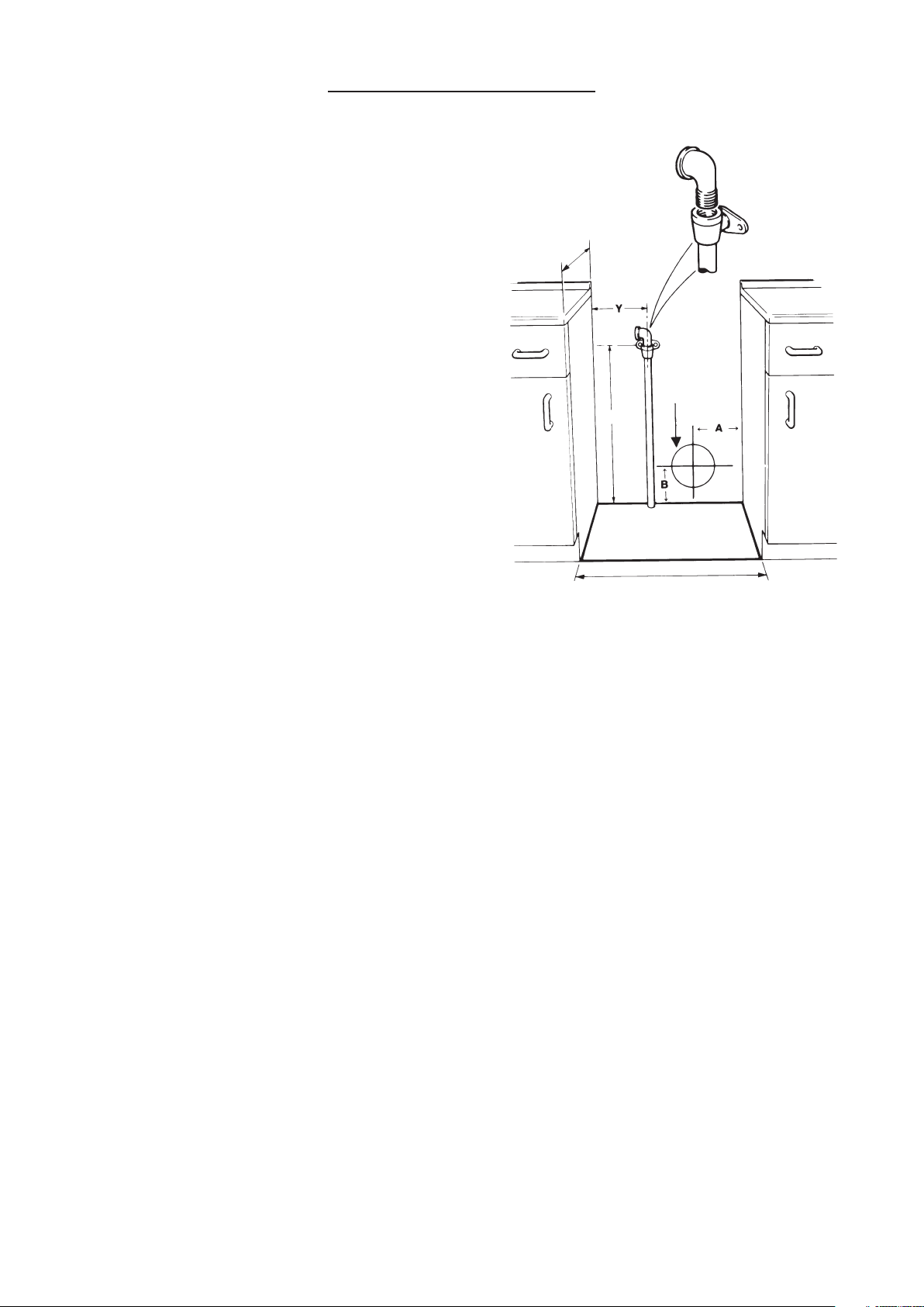
PERMANENT VENTING
Accessory wall/window vent kit CL005 is available:
See illustration for necessary hole through wall. Dim A =
200mm and Dim B = 100mm for direct alignment.
Note Dim B may be increased to 200mm to facilitate easier
drilling if required.
5 POSITION OF DRYER AND CONNECTIONS
The illustration shows the minimum space required by the
dryer and the position of the gas wall connector. It is not
acceptable to use a forward facing mounting plate
because of the space limitation. The sideways facing
assembly must be used and this should be fitted so that
the flexible hose hangs down from the bayonet connector.
A 13 Amp socket must be provided within a distance of 1.4
m (55 in.) of the cable entry into the dryer. The socket must
have an efficient earth connection.
If the dryer is to stand on a surface above the floor or on
top of a washing machine (using the Stacking Kit) then the
750 mm dimension is measured above the supporting
surface.
If the dryer is installed under a worktop there must be a
minimum gap of 15 mm between the top of the dryer and
the underside of the worktop to allow for ventilation.
If it is intended to move the dryer regularly for use then the
Restraining Kit must be fitted to prevent possible damage
to the gas connection.
We also recommend the fitting of a restraining kit to any
dryer which is stacked.
If using accessories:
Wall/Window Vent Kit
Stacking Kit
Restraining Kit
See separate fitting instructions included with each Kit.
Y = 150 to 330 mm
600mm
750mm
600mm
115-125 mm
diameter
INSTALLATION
Page 5

5
6. OPERATIONAL CHECK
6.1 Remove the pressure test point screw from the gas
tee connection at the back of the dryer and connect
a gas pressure gauge.
6.2 Check that the dryer timer is in the 'off' position, and
that the heat switch is set to 'high'.
Remove anything from inside the drum, check that
the lint filter is fitted, shut the dryer door.
6.3 Turn on the gas, push the electric plug into the socket
and switch on the electricity supply.
6.4 Turn the timer clockwise past the dotted line marking
the cool-down period to a setting of at least 30 mins.
Check for ignition. If the gas fails to remain lit then
repeatedly turn the timer on and off (or open and
close the door) for periods of at least 30 seconds
until the air is removed from the system and burning
is continuous. Note that gas is not lit when the drum
is turning anti-clockwise.
6.5 With the gas burning ensure that the pressure is as
detailed in the Technical Data. Turn off and replace
the pressure test point screw. Check for soundness.
6.6 Switch on again and re-start so that the gas is
burning.Disconnect the flexible gas hose and check
that the solenoids can be heard to close. After 30
seconds turn on the gas and check that there is no
re-ignition. Switch the machine off and on again and
check for reignition.
6.7 Check that the operation of the machine does not
cause spillage of products of combustion from any
open flued gas appliance in the same room, or from
appliances in adjoining rooms, e.g. a gas fire or
central heating boiler.
6.8 In the event of an electrical fault after installation of
the appliance, preliminary electrical system checks
must be carried out (i.e. earth continuity, polarity and
resistance to earth).
6.9 IMPORTANT INFORMATION RE-FUNCTIONING
OF THE FULL SEQUENCE FLAME CONTROL
BOX.
THE FULL SEQUENCE FLAME CONTROL BOX
ON THIS APPLIANCE REQUIRES A 6 SECOND
RE-SET PERIOD FOLLOWING EACH
INTERRUPTION OF INPUT VOLTAGE.
6 SECONDS DELAY IS REQUIRED BETWEEN
EACH ATTEMPT TO RESTART THE APPLIANCE
FOLLOWING SWITCHING IT OFF, OR AFTER
OPENING THE DOOR.
7 AIRFLOW
It is most important that airflow to the plinth is not
restricted.
8 MAINTENANCE
It is recommended that the appliance is serviced
annually by a person competent to service gas fired
tumble dryers.
9 STACKING
Instructions for stacking, if required, are supplied
with the stacking kit.
PROGRAMME
Clockwise rotation of the control knob closes switch
contacts within the timer to: a) energise the drive motor,
and b) energise the full sequence flame controller.
The timer switch controlling the drive motor and the timer
motor, remains closed until the timer motor mechanism
returns the control knob to the '0' position. The timer
switch controlling the full sequence flame controller
opens 12 minutes earlier to provide a cool-down period.
The full sequence flame controller opens the tandem
solenoid gas valves after a delay time of about 8 seconds
and operates the pulsing spark ignition. If the flame is not
detected by the flame failure electrode within 10 seconds
then the valves are closed. The system must then be reset by switching the machine off and re-starting.
The heat selector switch provides options for either 60°C,
or 50°C, exhaust thermostat control. This results in the
burner cycling on and off giving Ionger than anticipated
drying times. Drying times vary depending on the weight
and size of the articles, type of fabric, dampness etc.
These thermostats turn off the heating towards the end of
the chosen cycle and so avoid waste of energy. The
lower temperature thermostat prevents delicate fabrics
from getting too hot with possible risk of damage.
An inlet thermostat is fitted in the ducting at the back of
the dryer. It may also operate under certain other
conditions of restriction of the air-flow, for example, an
overloaded drum or blocked lint filter. This thermostat
switches off the flame controller. This will result in the
burner cycling on and off giving longer than anticipated
drying times. Drying times vary depending on the weight
and size of the articles, type of fabric, dampness etc.
Should the thermostat fail there is an inlet cut-out
connected in circuit with the gas valves. After operation,
the cut-out must be re-set to restore heating but a service
call may be required to correct the initial fault.
The conditions of failure of the air flow, blow-back, or of
gas interruption are detected by the flame failure
electrode and the system is shut-down.
Both drum rotation and heater control are switched off
when the door is opened and switched on when the door
is reclosed.
For programme times see chart on dryer control panel.
Note: Do not allow fluff to accumulate around the dryer.
Page 6
6
RECOMMENDATIONS FOR DISMANTLING
Note: Re-assembly should be done in reverse
sequence to these instructions.
HEATER ASSEMBLY REMOVAL
Heater Assy. (32), Solenoid Coil (45 or 45A), Flame
failure Electrode (33), lgnition Electrode (39).
Withdraw the 2-screws securing the Plinth (199) to the
Cabinet, unhook the bottom edge fixing, and remove it.
Separate the 4-way Housing (31 ) to release the wiring
from the Heater Assy. to the Cabinet.
Lay the dryer flat on its front, supported to take the
weight from the door and controls.
Withdraw the 6-screws securing the Cover Piate (19) to
the Back Panel (24) and remove it. Pull out the Exhaust
Tube (30).
Withdraw the 4-screws securing the Hot Air Elbow Assy.
(20) to the Back Panel (24) and remove it.
Disconnect the External Feed Pipe (15) from the Tee
Piece (27).
Pull the connectors off the Flame failure Electrode (33)
and the ignition Electrode (39).
SERVICE INSTRUCTIONS
Heat
Heat
Page 7

7
Withdraw the 3-screws and shakeproof vvashers (13)
securing the Flame Tube Assy. (34) to the Cabinet base.
Note: On re-assembly the shakeproof washers must be
replaced to ensure a good earth connection.
Lift out the Heater Assy.
To remove either solenoid coil (45 or 45A) disconnect the
electrical connectors, unscrew the nut (44) or remove circlip
(52) from the top of the valve and lift off. When removing
solenoid coil (45A), take care not to misplace the spring (53).
To remove the sensing electrode (33), withdraw the screw
(41) lockwasher (482) and nut (411 ) securing it to the Flame
Tube Assy. (34). Note on re-assembly the lockwasher (482)
must be replaced to ensure a good earth connection.
To remove the Ignition Electrode (39), withdraw the screw
securing it to the top of the Heater Tube Assy. (34).
If there is a fault in the valves, burner or other parts of the
gas line, then the Heater Assy. (32) must be replaced.
INLET THERMOSTAT & THERMAL OVERLOAD CUTOUT (TOC) REMOVAL
Lay the dryer flat on its front, supported to take the weight
from the door and controls.
Withdraw the 6-screws securing the Cover Plate (19) to the
Back Panel (24) and remove it. Pull out the Exhaust Tube
(30). Disconnect the Faston connectors from the 4-way
Terminal Block (142) as necessary (see wiring Diagram for
colour code). Cut off the 2-Cable Ties (387). Note: on
reassembly these must be replaced by new components to
secure thermostat wiring away from contact with the Drum.
Withdraw the 16-screws securing the Rear Banjo (18) and lift
it off.
Withdraw the screws securing the Thermostat (230) and/or
TOC (38) and pull the connecting wires through the
Grommet (25).
Note: Operation of the TOC should only occur if the
thermostat has failed. If the TOC should also fail this results
in high temperatures in the dryer.
Assembly
(359)
Page 8

8
FAULT FINDING
In the event of an electrical fault carry out the preliminary electrical system checks i.e. earth
continuity, polarity, and resistance to earth.
Use each chart to locate the fault causing the dryer to operate incorrectly as follows:
Chart No.
1 Motor does not run.
2 Motor runs but full sequence control does not produce ignition spark.
3 Motor runs, Full Sequence Control produces ignition sparks, but gas does not ignite.
4 Motor runs, gas ignites but burns for only a short period.
Chart 1. Motor does not run
Page 9

9
Chart 2.
Motor runs but full
sequence control does not
produce ignition spark
START
Exchange timer, Does control spark?
Does control spark with low heat
selected?
Change 50˚C exhaust thermostat
Does control spark?
Check continuity of red wire between
timer B2 and heat selector switch.
Are connections clean and tight.
Does control spark?
Exchange heat selector switch.
Does control spark?
Exchange both exhaust thermostats
(50˚C and 60˚C) and inlet thermostat
130˚C (brown wires)
Does control spark?
Exchange full sequence control unit.
Does control spark?
With timer ON (30 min) is voltage between output
B2 on timer and TB-N 230v?
Does control spark with high
heat selected?
Disconnect both red wires at timer B2. Reconnect
only red wire from heat selector to timer B2.
Caution the other red wire is live. Is voltage
between heat selector switch and TB-N 230V?
With red wire still disconnected is voltage between
output of heat selector switch and TB-N 230V at
high heat setting and zero volts at low setting.
Is voltage between brown wire in control box
multiway connector and TB-N 230V?
Check HT lead is connected to control and
electrode. Does control spark?
Check condition of ignition electrode and spark
gap is correct by removing heater assembly.
Does control spark?
Does gas light?
Does gas stay on?
Machine operating. Instruct
users as necessary
Yes
Yes
No
Yes
No
No
No
No
Refer to chart 3
No
Refer to chart 4
No
No
No
No
No
Yes
Yes
Yes
Yes
Yes
Yes
Yes
Yes
No
Yes
Yes
No
No
No
Yes
Yes
Yes
Page 10

10
Chart 3. Motor runs Full Sequence Control produces ignition sparks, but gas does not ignite
Page 11

11
Chart 4. Motor runs, gas ignites but stays on for only short period
Before proceeding, ensure polarity of 13 Amp supply socket and earthing is correct.
Is weight of load suitable?
Is filter clean? Is vent
hose or terminal
unobstructed? Is vent
terminal unaffected by
wind conditions that may
cause back pressure?
Is flame failure electrode
correctly positioned, and
undamaged? Is wire to
terminal 9 undamaged and
connections tight? Is rear
drum seal complete? Is rear
elbow and plinth attached
correctly?
Exchange full sequence
control and/or gas control
relay PCB and/or
thermostats as necessary
until gas stays on.
Machine operating.
Instruct user as necessary.
Yes
Yes
Yes
Start
Check gas pressure with all
other appliances in operation
does gas stay ON?
No
Yes
Rectify as necessary
does gas stay ON?
Yes
No
No
No
Page 12

12
WHITE KNIGHT BG 43A_
CROSSLEE P.L.C.
Page 13

13
WHITE KNIGHT BG 43A_
CROSSLEE P.L.C.
EXPLODED VIEW 1
Page 14

14
WHITE KNIGHT BG 43A_
CROSSLEE P.L.C.
EXPLODED VIEW 2
REAR ASSEMBLY VIEWED FROM FRONT
Page 15

15
WHITE KNIGHT BG 43A_
CROSSLEE P.L.C.
EXPLODED VIEW 3
INTERNALS VIEWED FROM REAR
Page 16

WHITE KNIGHT BG 43A_
CROSSLEE P.L.C.
EXPLODED VIEW 4
INTERNALS VIEWED FROM REAR
16
Page 17

17
WHITE KNIGHT BG 43A_
CROSSLEE P.L.C.
EXPLODED VIEW 5
HEATER ASSEMBLY
Page 18

18
Page 19

19
Page 20

BG 43A_ Installation/Service Book 4213 094 67791
Manufactured by: Crosslee plc. Lightcliffe Factory, Hipperholme, Halifax, West Yorkshire HX3 8DE.
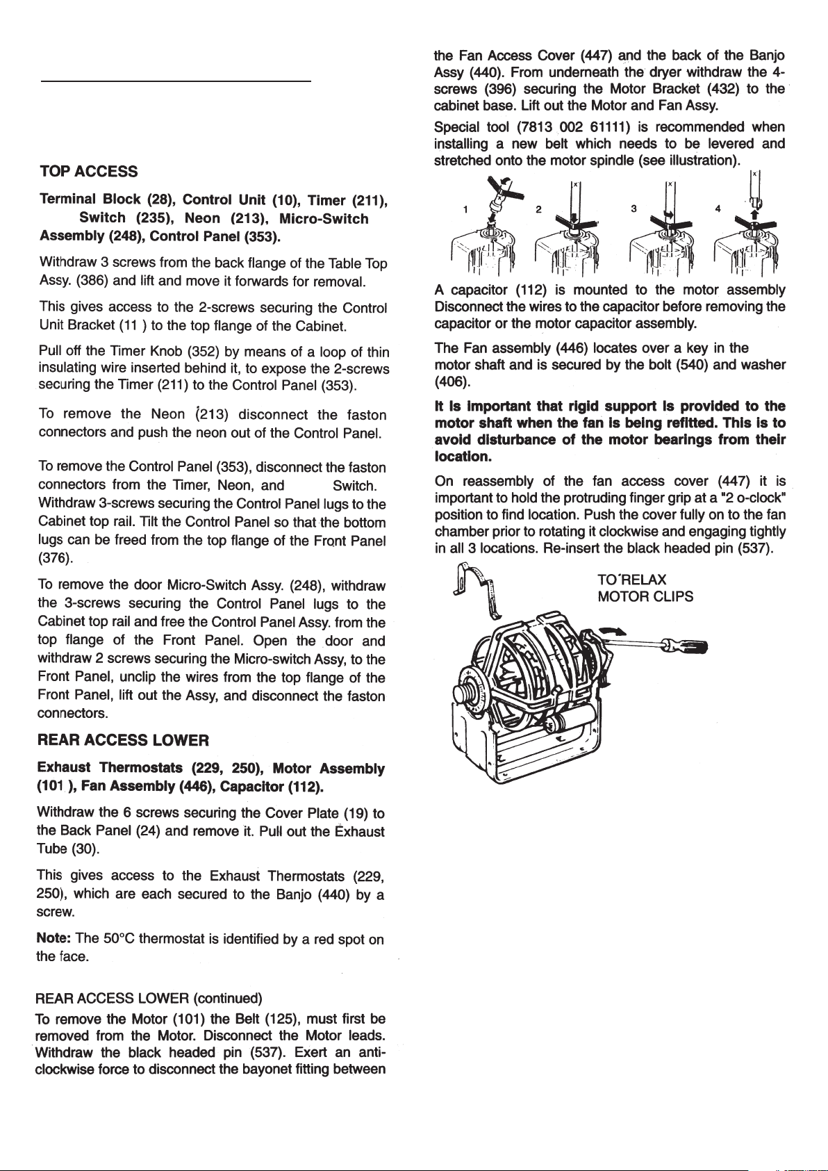
 Loading...