

Page 1
Trouble Shooting & Safety Guide
Wiring Diagram
Exploded Views
Parts List
September 2016
8kg
Condenser Tumble Dryer
UK
White Knight - B96M8W
SERVICE MANUAL
Note: Please read before servicing the unit. Any problems: contact your service centre
Page 2
CONTENTS – B96M8W
2. User error checklist
3. Control panel connection diagram
3.1 Lack of display on control panel
3.2 Drum does not turn but the control panel displays correctly
3.3 Heating system failure
3.4 The drum turns but the appliance fails to dry
3.5 The dryer makes an abnormal noise when operating
3.6 The dryer produces an abnormal smell when operating
3.7 The LED displays when the dryer is operating
3.8 Error warning codes
4.1 Disassembly warnings
4.2 Disassembly methods
5. Wiring diagram
6. Exploded view
2. User error checklist – please check prior to service
Symptoms
The drum does not rotate
The dryer gives out abnormal
heat
The clothes are creased or
shrunk
Check whether:
There is power to the appliance
The door is closed
The correct program has been selected and the start button has been
pressed
The heat exchanger is assembled and fit correctly
The maintenance cover is locked in place
The door is sealed correctly
The dryer is overloaded
The correct program has been selected
Page 3
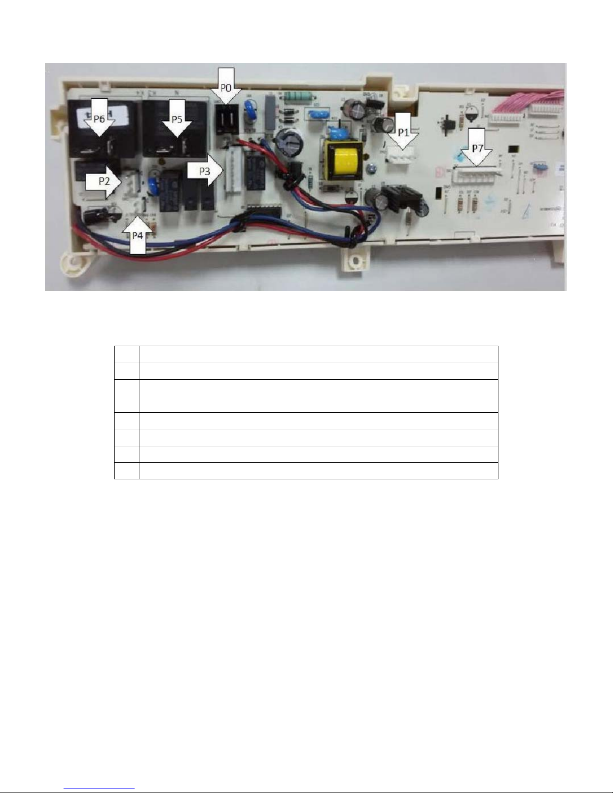
3. Control panel connection diagram
P0 Live and neutral
P1 Load moisture sensor
P2 Motor L + heater (700W) L
P3 Drum light and pump
P4 Door switch
P5 Heater N+ motor N
P6 Heater (1600W) L
P7 Water level sensor, Inlet thermistor and Exhaust thermistor
Page 4
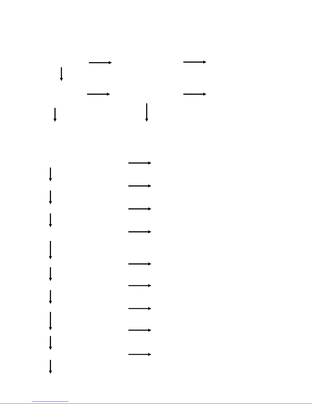
3. FAULT FINDING
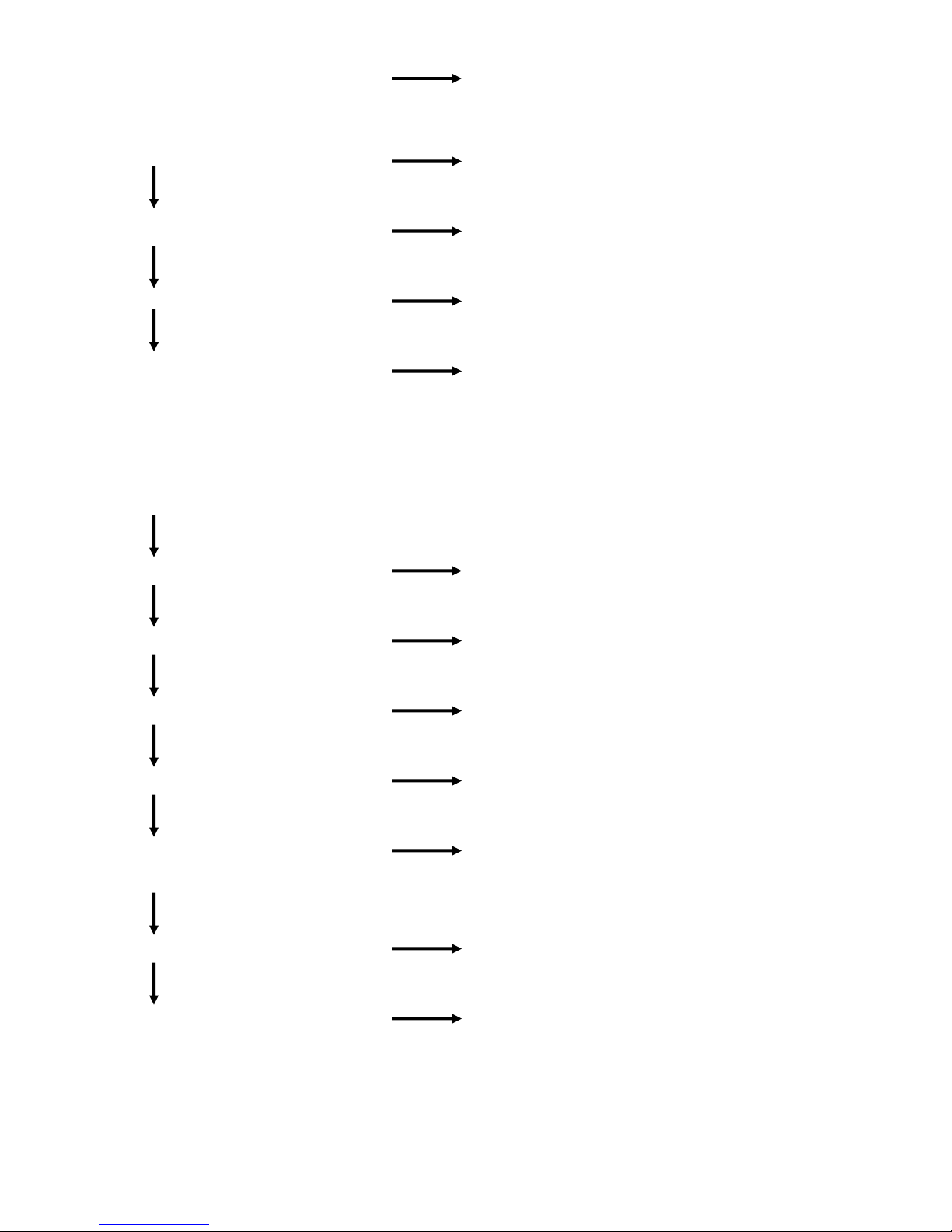
3.1 Lack of display on control panel
Check if power is NO YES
getting to the appliance Check fuse for continuity Replace fuse
YES
Switch off the appliance NO Check power cord and YES Replace the mains cable
Check for 230V between loom harness for damage or loom harness as necessary
pins P0 on PCB
YES YES
Replace the PCB Check the RFI filter for damage
3.2 Drum does not turn but the control panel displays correctly
YES
Check if the belt is loose or damaged Re-fit or replace belt
NO
YES
Check if the terminals of P2 are loose Ensure that the terminals are connected correctly
NO
YES
Check the front support wheel for damage Replace the front support wheel (including wheel shaft)
NO
YES
Check if the capacitor has correct value Insert or replace capacitor
and is connected to the loom
NO
YES
Check if the tension spring Install or replace the tension spring
NO
YES
Check the motor for damage Replace the motor
NO
YES
Check for blockage/binding when drum rotates Check and remove blockage
NO
YES
Check for damage to the drum bearing Replace the drum bearing assembly
NO
YES
Check any damage to door switch Replace the door switch
NO
YES
Page 5
Check loose connections or damage to loom Re-assemble or replace the loom
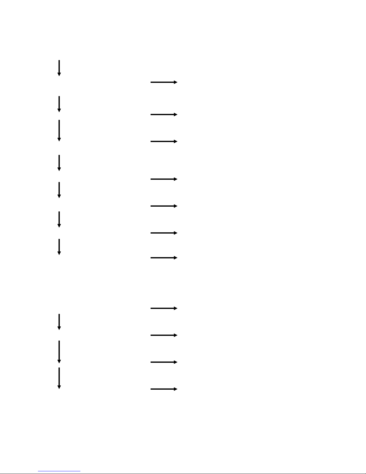
3.3 The heating system does not work
YES
Check if the “cool” program is in operation Re-test the appliance in a heating program
NO
YES
Check if terminal P4 is loose Re-attach terminals
NO
YES
Check if the loom is damaged Replace the loom harness
NO
YES
Check if the Inlet thermostat on the heater Replace the heater subassembly
assembly is damaged
3.4 The drum turns but the appliance fails to dry
Is the ambient temperature higher than 35°C
NO
YES
Check the correct program has been selected Select the correct program
NO
YES
Check if the dryer is overloaded The load placed in the drum must not exceed the
maximum load rating stated in the instruction book
NO
YES
Check that the filter is clean Clean the filter
NO
YES
Is the heat exchanger blocked Clean the heat exchanger
NO
YES
Is the Inlet thermostat damaged or has the thermal Reset the thermal cut-out if tripped. Replace the heater
cut-out tripped subassembly if damaged
NO
YES
Is the heater damaged Replace the heater subassembly
NO
YES
Check the load moisture sensors Clean and then check. If still faulty, replace.
Page 6
3.5 The dryer makes an abnormal noise when operating
Check to find the source of the noise
YES
Check if the screws holding the lifter to the drum Tighten the screws accordingly
are loose
NO
YES
Is the front support wheel damaged Replace the front support wheel subassembly including
shaft
NO
YES
Is the tension spring connected between the Reassemble the tension spring
motor and the base
NO
YES
Is the motor noisy Replace the motor
NO
YES
Check if the fan is loose or damaged Reassemble or replace the fan
NO
YES
Is the drum bearing/drive shaft damaged Replace the drum assembly
NO
YES
Does either the drainage or overflow Ensure the hoses are positioned correctly
pipe rub on the rotating drum
3.6 The dryer produces an abnormal smell when operating
YES
Is there any sign of deposits on the heater Clean the heater
NO
YES
Is the main drive belt slipping Replace the main drive belt. Check the spring providing
tension (between the motor and base)
NO
YES
Has the motor stalled Check for any signs as to why the motor stalled (e.g.
drum jammed). Replace motor if no issues found.
NO
YES
Check for any signs of overheating of electrical Replace any parts as necessary
components
Page 7
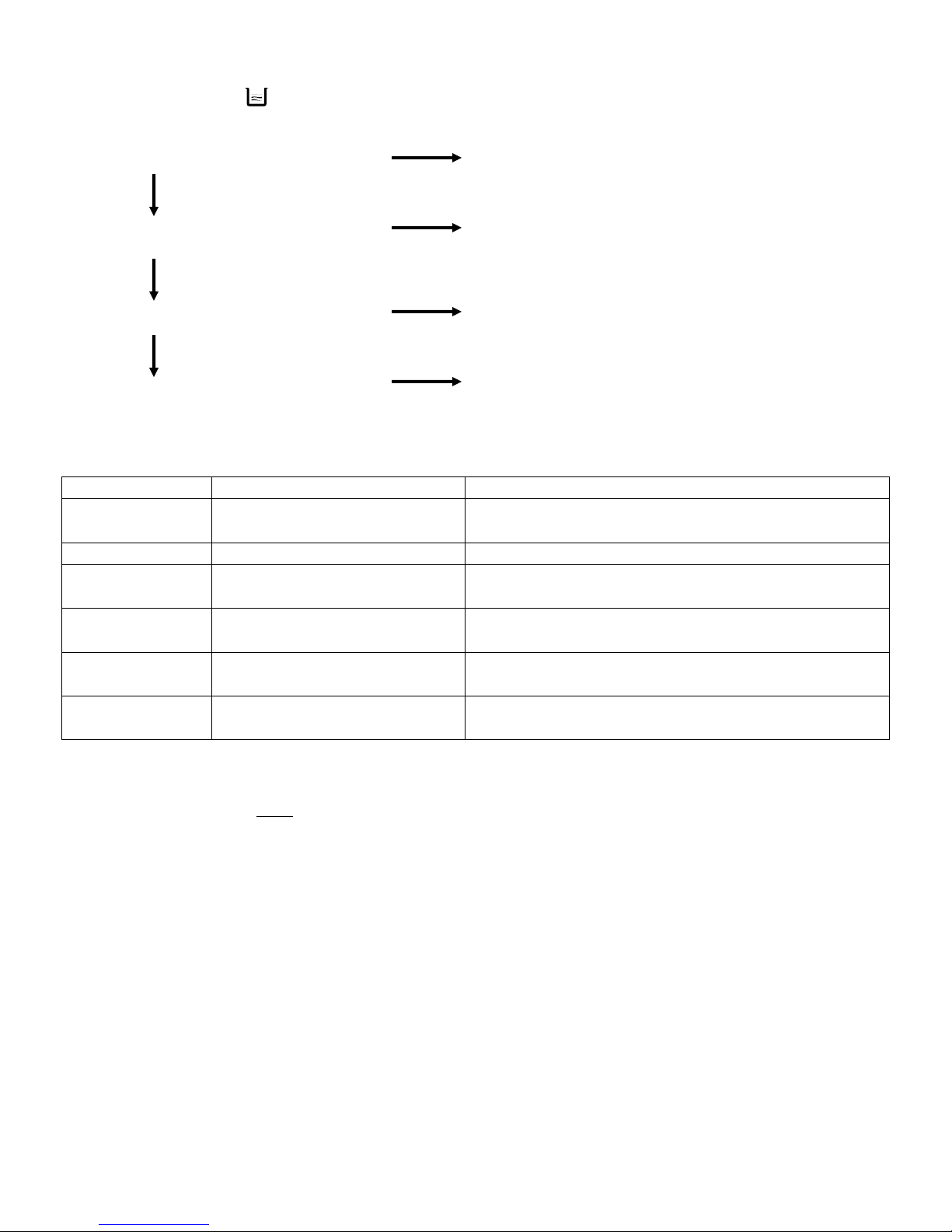
3.7 The LED displays when the dryer is operating
YES
Check if the bottle is full Empty the bottle
NO
YES
Check if the pump is connected correctly Attach the terminals accordingly or replace the loom
Check PCB for any signs of damage Check connections on PCB and replace if necessary
NO
YES
Check if the pump is damaged or blocked Replace or clean the pump
NO
YES
Check if the water level sensor is damaged Replace the water level sensor
3.8 Error warning codes
Error ‘code’ Error description Parts to check
Bottle full
indicator lit
Bottle is full of water
and bottle full indicator is lit
Check the water container, pump and water level
sensor
E30 Heater not working Check the heater and motor
Clean filter
indicator lit
E32
E33
E34
Filter mesh is blocked Clean the filter mesh and restart the machine
Load moisture sensor not
working
Inlet thermistor not functioning
correctly
Exhaust thermistor not
functioning correctly
Check the moisture sensors and restart the machine
Check the inlet thermistor (on heater assembly) and
check associated connections
Check the exhaust thermistor (below filter) and check
associated connections
4.1 Disassembly warnings
The mains cable must
be disconnected from the power supply when disassembling or repairing the
machine.
The loom harness and terminals used must be for the correct wire size and the correct tools must be
used to crimp any terminals onto the harness. Insulation tape must be used where appropriate.
When attaching terminals to the mating connectors, always ensure that they are pushed fully on.
When attaching a wire via a screw terminal, ensure that sufficient wire is underneath the screw
terminal. Ensure that the screw is tightened satisfactorily.
The loom harness should not touch any moving parts or sharp edges. The wiring route around high
temperature objects (e.g. motor) should be followed as per the initial construction.
Always use the specified screws
Page 8

4.2 Disassembly methods
1. Control panel assembly disassembly
1. Unfasten the two screws at the rear of the
top cover and slide top cover backwards
2. Remove the bottle
3. Remove 4 screws at the front of the dryer
from the control panel and cross brace
4. Remove 2 screws inside the slots on the
control panel
5. Remove all of the connections from the
back of the PCB
Page 9

6. Remove the screws holding the PCB to the
control panel. The PCB’s can be removed by
unscrewing and unclipping where necessary.
2. Disassembling the RFI filter and water level sensor
Disassembling the RFI filter:
Remove the loom terminals from the filter. Unfasten
the two screws from the filter in order to remove the
filter from the upper bracket.
Disassembling the water level sensor:
Remove the top cover (screws at rear of appliance)
and left-hand side panel (screws along top, at rear
and underneath appliance) from the appliance.
(1) Pull out the drainage hose connector from the
pump cover.
(2) Remove the pump cover(s)
(3) Remove the nut on water level sensor to
allow the water level sensor to be removed
from the pump cover. Unclip the wires.
3. Disassembling the door
1) Remove the screws holding the hinge to the front
panel. Lift the door to extract the hinge from the
panel and place on a soft surface to avoid scratching
the door.
2) Remove the screws on the inside of the door.
3) The door should now be able to be stripped into
its constituent parts.
Page 10

4) Push the two pins of the hinge to separate the
hinge..
4. Disassembling the heater
1) Remove the screws from the rear panel
2) Remove the screws from the air ductwork below
the heater
3) Remove the top cover by unscrewing the screws
at the back of the appliance.
4) Disconnect the loom harness from the RFI filter
5) Disconnect the terminal from the heater connector
Page 11

6) Remove the cable clamp holding the wires to the
backpanel
7) Remove the screws from the heater
5. Disassembling the drum
1) With the side panels and the top cover of the
appliance removed, remove the bracing struts
between the front and backpanels. Remove the
screws which hold the metal backpanel to the plastic
base. The drum and the backpanel should now come
away as one item.
2) Remove the main drive belt from the drum
subassembly.
3) Remove the two screws from the bearing cover
4) Remove the ring seal from the bearing cover
Page 12

5) Remove the nut with adjustable wrench or similar
6) Remove the drum shaft ring
7) Remove the backpanel from the drum
8) Remove the other two shaft rings
Page 13

5. Wiring Diagram
1-Pump 2-Drum light 3-Door Switch 4-Moisture level sensor 5-Mains cable 6-RFI filter
7-Motor 8-Capacitor 9-Heater 10-Inlet thermistor 11-Water level sensor 12-Exhaust thermistor
6. Exploded View
Page 14

Exploded View Base
Page 15

Exploded View Front Support
Page 16

Exploded View Control Panel & Water Bottle
Page 17

Exploded View Drum
Page 18

Exploded View Front Panel
Page 19

Exploded View Door
Page 20

Parts for Model White Knight B96M8W
ITEM No DESCRIPTION CODE BOM code
1.1 Handle Assembly 4213 092 69251 301160760440
1.2 Base Assembly NOT AVAILABLE 301160760035
1.2.1 Condenser Cover 4213 092 65211 301160700025
1.2.2 Sump Cover 4213 092 65341 301160700024
1.3 Capacitor 4213 092 65291 302460700011
1.4 Leg 4213 092 65311 301160700027
1.5.1 Short Belt 4213 092 65271 302760700002
1.5.2 Motor Support 4213 092 65251 301160700033
1.5.3 Motor 4213 092 65241 302460760017
1.6 Pump Protection Cover 4213 092 65191 301160760011
1.7 Pump Cover 4213 092 65181 301160700028
1.9 Drain Hose Joint 4213 092 65901 301160700030
1.10 Drain Pump 4213 092 65171 302460700014
1.11 Water Level Sensor 4213 092 65201 302460700015
1.12 Noise Absorber 4213 092 65321 302160700006
1.13 Fan Assembly 4213 092 65231 301160760030
1.14 Fan Assembly 4213 092 65261 301160760029
1.15 Tensioner Spring 4213 092 65281 302960700002
1.16 Condenser Assembly 4213 092 65001 301560760002
1.17 Cover Fan 4213 092 65221 301160700026
2.1 Front Support Seal 4213 092 65111 302160700003
2.2 Humidity Sensor 4213 092 65101 302460700024
2.3 Bracket Humidity Bar 4213 092 69261 301160700038
2.4 Noise Absorb Cotton 4213 092 69271 302160700005
2.5 Holder Lamp 4213 092 65071 302460700013
2.6 Lamp 4213 092 65091 302460700012
2.7 Front Support Assembly 4213 092 65061 301160700037
2.8 & 2.9 Cover Lamp & Seal 4213 092 65081 301160700039
2.10 Lint Filter 4213 092 65051 301160700070
2.11 Wheel Assembly 4213 092 65121 302960860008
2.12 Temperature Sensor 4213 092 65151 302411600802
2.13 Seal Thermistor 4213 092 65141 302760700003
2.14 Nut 4213 092 65741 302560700003
3.1 PCB 4213 092 64891 302460860001
3.2 Control Panel Assembly 4213 092 64881 3011607A0145
3.3 Knob 4213 092 64871 301160760018
4.1 Drum 4213 092 66091 301160760105
4.2 Cover Bearing 4213 092 66111 301260700013
4.3 Seal Cover Bearing 4213 092 66101 302760700007
4.4 Nut NOT AVAILABLE 302502000102
4.5 Cover Back NOT AVAILABLE 301260700016
4.6 Seal Back Assembly 4213 092 65391 302160700004
4.7 Bearing House Assembly 4213 092 65361 301260760022
4.8 Drum Assembly 4213 092 65401 301260760044
4.9 Lifter NOT AVAILABLE 301160700045
4.10 Cover Basket NOT AVAILABLE 301160700046
4.11 Heater Assembly 4213 092 65371 302460700016
5.1 Front Panel 4213 092 65561 301260700011
5.2 Door Lock Assembly - up to WK1537 4213 092 65591 301160700021
5.2 Door Lock Assembly - from WK1538 4213 092 68531 302460860004
5.3 Positioning Pin NOT AVAILABLE 301160760023
5.4 Cover Switch 4213 092 68531 302411500061
www.whiteknightspares.co.uk www.whiteknightrange.co.uk
Page 21

6 Door Assembly - up to WK1537 4213 092 64901 301160700018
6 Door Assembly - from WK1538 4213 092 69281 12138200A02721
6.1 Outer Frame 4213 092 64911 301160700053
6.2 Protect Cover 4213 092 64921 301160700057
6.3 Inner Ring Seal 4213 092 64941 302760700005
6.4 Door Plunger - up to WK1537 4213 092 64961 302960700011
6.4 Door Plunger - from WK1538 4213 092 68541 302960700015
6.5 Inner Ring (2 Ribs) - up to WK1537 4213 092 64951 301160700054
6.5 Inner Ring (No Ribs) - from WK1538 4213 092 68561 301160700054
6.6 Door Hinge Pedestal 4213 092 64981 301160700058
6.7 Parallel Pin NOT AVAILABLE 302960700010
6.8 Hinge Support 4213 092 64971 302960700009
6.9 Window Door 4213 092 64931 301160700056
7 Top Cover Assembly 4213 092 65491 301160700015
8 Upper Support 4213 092 65441 301160700012
9 Bottle Assembly 4213 092 65431 301160700069
10 Housing Bottle 4213 092 65451 301160700011
11 Water Bottle Handle And Printing 4213 092 65421 3011608A0038
12 Top Bracket 4213 092 65601 301260700009
13 Bracket Side 4213 092 65461 301260700006
14 Right Top Bracket 4213 092 65471 301260700007
15 Air Inlet Grill NOT AVAILABLE 301160760146
16 Long Belt 4213 092 65511 302760700001
17 Cover Back NOT AVAILABLE 301260700012
18 Side Panel 4213 092 65551 301260700008
19 Maintenance Cover 4213 092 65571 301160760145
20 UK Power Cord 4213 092 65501 302460760022
21 Electric Filter 4213 092 65481 302360700001
22 Door Gasket - up to WK1537 4213 092 65581 301160700007
22 Door Gasket - from WK1538 4213 092 68551 302760860001
23 Overflow Hose 4213 092 65411 301160700010
24 Drain Hose 4213 092 65331 302760700008
25 Inlet Duct 4213 092 65531 301260700010
www.whiteknightspares.co.uk www.whiteknightrange.co.uk
 Loading...