

Page 1
0
White Knight Fluid Handling Inc.
187 E 670 S Kamas, Utah 84036 USA
Phone 435.783.6040 • Fax 435.783.6128 •Toll Free 888.796.2476
wkfluidhandling.com
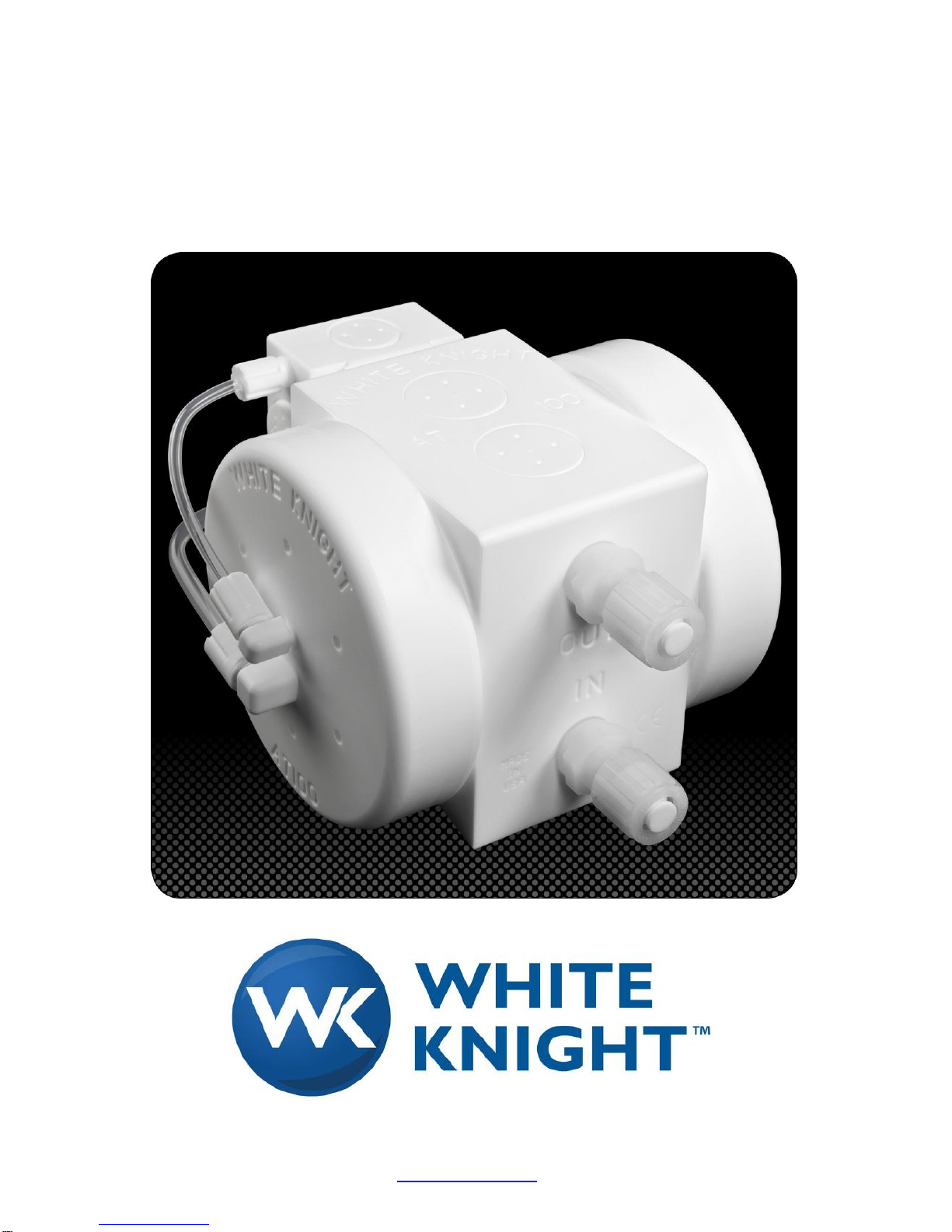
AT100 Owner’s Manual
WHITE KNIGHT
AT100 Owner’s Manual
Revision 10
Page 2

1
Revision 10
Page 3

2
TABLE OF CONTENTS
Recommended Mode of Installation 4
When Replacing a Competitor’s Pump 8
Cautions on Installation 10
Exploded View 11
Installation Instructions 12
Pump Stroke & Leak Detect Installation Instructions 13-17
Footprint 18
Flow Curves 18
Air Consumption 19
Air Supply Pressure to Temperature Limits 19
Rebuild Information and Options 20
Trouble Shooting 20
Decontamination Instructions 21
Ordering Instructions for non EXT 100 Series pumps 22
Rebuild Service or Kit Ordering Instructions 26
Warranty 27
Pulsation Dampening 28-31
Other Accessories 32
Electronic Accessories 33
Decontamination Certificate 34
Pricing, performance data, claims and other information contained within this owners manual is
subject to change without notice.
Revision 10
Page 4

3
Congratulations!
You are about to install a pump that has become legendary in the high purity
chemical pumping industry. White Knight is a leader in no metal high purity
pumps and continues to drive the industry with new technology. Since the
inception of White Knight in 1995, we have been awarded over 10 US patents for
our designs, with multiple other patents pending! Currently, White Knight
produces over 20 size/model combinations of zero metal high purity pumps, far
more than any other producer of high purity pumps anywhere. White Knight has
also been the recipient of multiple prestigious industry awards for its designs.
Other than PFA tubing and a few ceramic and electronic components and
assemblies, all parts of White Knight pumps are manufactured right here at our
plant in Kamas, Utah. This allows us to be rigorous in our quality assurance
process where almost all processes are performed right here at White Knight.
White Knight molds its own PTFE and machines all of its own PTFE, PFA, and
plastic components. This ensures that strict cleanliness procedures are always
followed and that components are built under consistent methods and conditions
to make our products as reliable and consistent as possible.
Your new pump was assembled and tested in a class 100, temperature and
humidity controlled cleanroom. It successfully underwent a battery of tests and
was then dried out and double bagged in the cleanroom to ensure cleanliness
and its operational integrity.
Before installing your White Knight pump please carefully review this owners
manual. There are many helpful hints and ways to optimize the installation of
your White Knight pump as well as instructions and requirements for installation
and use.
White Knight also provides many accessories that will enhance the abilities of
your White Knight pump. Many of these are briefly described in this manual.
We have gone to great lengths to provide you with what we believe to be not only
the best value for the money in high purity pumps, but the best high purity pump
period. We hope that you agree.
John Simmons
President, White Knight Fluid Handling, Inc.
Revision 10
Page 5

4
Recommended Mode of Installation New System Design
The following is an attempt to go over some basic physics of White Knight pumps
so that care may be taken in the design phase of equipment or applications
wherein White Knight pumps are used. Following the principles described in this
document will ensure the most practical and reliable installation of White Knight
pumps, though it is understood that the ideal mode may not always be possible.
Several principles should be understood before proceeding.
SUCTION LIFT: Any air driven pump pushes better than it lifts. This means
that if you have to move liquid up ten feet, that the pump will move more liquid
faster (and in most cases the pump will be more reliable) if the pump is
installed at liquid level and is allowed to push the liquid up the ten feet.
Rather than being installed at the ten foot level to lift liquid up to the delivery
level. The same should be said for long runs. The best installation is with the
pump as near the source as possible.
RESTRICTION OF LIQUID INLET LINE: Restricting the liquid supply of the
pump causes the pump to work harder and should be avoided when possible,
particularly in the event of pumping more viscous liquids.
UNDER SUPPLY OF OPERATIONAL AIR: Under supplying of air to an air
driven pump can cause a pump to run erratically. Air driven pumps vary
throughout the cycle as to how much air they require. Though the rate of air
usage is averaged for air usage charts, if the bare minimum air supply (as
shown on the charts) is provided, there are fractions of seconds during a
cycle where a pump would be “starved” for air. This could cause a pump to
run erratically or to stall. In many instances, it could affect the ability of the
pump to self-prime. White Knight publishes the size of air line orifice for all of
its pumps to avoid this situation. These sizes are listed on the “Warning”
sheet shipped out with every pump and included in this manual.
DRY RUNNING: While the consequences vary from model or brand of air
driven pump, it is always best to limit the amount of dry running that the pump
is required to perform. The worst case is in the instance of pumps with
wetted shafts such as the White Knight AT, AP, APFM, and Renaissance
series as well as some other brands of air driven pumps. Pumps with wetted
shafts use the liquid that they are pumping to lubricate the shaft and seals.
When these pumps are run dry, they are not receiving sufficient lubrication to
Revision 10
Page 6

5
keep abnormal wear from the shaft and/or seal. When this occurs, the pump
gradually loses its ability to self-prime. It is White Knight’s recommendation
that all air driven pumps with wetted shafts be installed in a flooded style (with
gravity feeding liquid to the pump). This does not mean that the pump must
be installed in a flooded style, remember that we are talking about “ideal”
conditions. It should also be understood that when any air driven pump is
running dry, it is cycling faster than it would be if it were pumping liquid. This
means that in the same amount of time, a pump running dry will achieve a
higher number of cycles against its life expectancy than a pump that is
pumping liquid, thereby shortening (in time) the life of the pump.
HEAD PRESSURE: While some air driven pumps common to the high purity
chemical industry limit the percentage of head pressure (amount of liquid line
pressure that the pump is pumping against) to air supply pressure, no White
Knight pumps are restricted in any such way. White Knight pumps can be
installed in any head pressure situation up to dead head (liquid line pressure
equaling air supply pressure, which equates to no flow). White Knight pumps
come standard to work in high back pressure situations. For applications
where high head pressures are needed the Renaissance series of pumps are
recommended as they are capable of running at air pressures of up to 100
PSI.
DEAD HEAD: Though some air driven pumps in the industry do not allow it,
White Knight pumps can actually be controlled by opening and closing the
outlet line of the pump.
CLOSED OR PLUGGED LIQUID INLET LINE: Air driven pumps should not
be controlled by closing the liquid inlet line to the pump. This causes undue
stress on bellows or diaphragms, and in many cases can cause a pump to
“race” thereby subtracting cycles from its life expectancy at an alarming rate.
ORIENTATION: While it is possible to install air driven pumps in other than
up right positions in flooded suction circumstances, it is not recommended.
Check valves within White Knight pumps are actuated by gravity and/or flow.
Therefore, a pump installed in the upright position would run more efficiently
than a pump that was installed in another way. A White Knight (and most
other air driven pumps in the high purity chemical industry) will not prime
themselves if installed in any way other than upright (within a few degrees).
THERMAL CYCLING: Some pumps in the industry have limits on or special
maintenance requirements for pumps in conditions that thermal cycle. No
White Knight pumps have special requirements for thermal cycling
applications, but pumps must be operated within their respective temperature
to pressure limitations.
SUPPLY PRESSURE RECOMMENDATIONS: While all manufactures of air
driven pumps set a limit (red line) on how much air pressure can be used for
Revision 10
Page 7

6
pump operation, it is always best to operate a pump at lower than red line
supply pressures. Life expectancy goes up as supply pressure goes down.
The life of many air driven pumps goes up significantly if the pump is
operated at between 60%-70% of red line pressures, particularly in open loop
systems where there is very little head pressure to slow pump cycling.
PASSING SOLIDS: In any instance where pumps are installed in an
application where solids could be introduced into the liquid, a pre pump filter
such as the White Knight Catcher should be installed in the inlet line going
to the pump. These pre pump filters are designed to catch solids before they
get to the pump where they could damage bellows, diaphragms, or other
parts of the pump. Of particular concern are shards from broken wafers in
semiconductor manufacturing. Care should be taken in selecting the pre
pump filter. Some pre pump filters have a very fine screen that screens out
anything that could damage a pump, but screens this fine come with other
problems. Some chemistries including but not limited to sulfuric acid and
phosphoric acid can begin to produce crystals similar in size and shape to
table salt crystals. Such crystals can plug up the screen and cause undue
stress to the pump, particularly to bellows or diaphragms. White Knight does
not cover such damage under warranty. While there is no perfect size of
screen that keeps out the bad without plugging up, the best scenario is to use
White Knight Catcher pre pump filters. With the Catcher the screen is
large enough to keep from becoming plugged in normal industry conditions.
And, when a Catcher is used in conjunction with a White Knight pump, if a
solid passes through the Catcher and damages the pumps (very unlikely)
White Knight will repair the pump under warranty.
OVERSIZED INLET LINE: White Knight (as well as many other air driven
pumps) are best installed with liquid inlet lines larger than the liquid outlet
lines, particularly in open loop systems where there is very little head
pressure. This reduces strain on bellows and diaphragms and also in many
cases reduces surge in the outlet line from the pump.
PULSATION: White Knight pumps are famous for the low surge created in
outlet lines down stream from the pump. However, there are things that can
be done to reduce surge even further. White Knight offers Flatliner
Pulsation dampeners in various sizes to minimize surge created by air driven
pumps. In open loop systems where there is very little head pressure, most
White Knight customers find it unnecessary to use additional pulsation
dampening devices, however, as head pressure increases, the requirement
for pulsation dampening increases. A less expensive way to lessen pulsation
in the outlet line is by the usage of a “stand tube”. This is accomplished by
installing a Tee in the outlet line from the pump. The Tee is pointed upward
and a piece of tubing (typically 3-4 feet long) is stood up and capped. As the
pump runs, the liquid pressure in the line compresses the air in the stand tube
during the pressure part of the pump stroke and the compressed air in the
stand tube pushes liquid back into the line during the shift part of the pump
Revision 10
Page 8

7
cycle. These stand tubes are pretty effective, however, they must be
monitored and from time to time the cap may need to be removed to allow the
tube to release liquid and refill with air.
LEAKY LINES: All liquid tubing connectors upstream and downstream from
the pump should be tight and leak proof. But on the inlet side of the pump, a
leak may not be noticed, as if the leak is sufficiently large, the pump will
simply not prime. Select a quality type of liquid connection throughout your
system and make sure that they are installed properly.
BOILING LIQUID: In the event of pumping chemistries at or near their boiling
point, it must be remembered that the boiling temperature of any liquid
reduces under vacuum conditions. As a pump sucks liquid into it, the liquid in
the supply line to the pump is under a vacuum condition. Depending on the
amount of vacuum and the temperature of the liquid, liquid could boil in the
outlet line of the pump when it is not boiling in the tank (or other supply
reservoir). Placing the pump as close as possible to the tank and with as little
vertical lift as possible (the pump being flooded by gravity is ideal) minimizes
boiling in the inlet line. Boiling of the liquid in the inlet line causes a pump to
“race” thereby shortening its life, and in extreme circumstances will cause the
pump not to prime.
FLAMMABLE SOLVENTS: High purity pumps are frequently used to pump
flammable solvents. Any system used to pump flammable solvents should be
properly grounded to avoid ignition by static charge. Where high purity
pumps are constructed from insulative materials (PTFE and PFA) grounding
the pump is not sufficient. A test from River’s Edge on using insulative pumps
to pump flammable liquids indicated that the liquid itself must be grounded
and that other procedures should be followed. A copy of the test is available
from our web site or may be acquired by calling or emailing us at White
Knight. Designs planning the use of any insulative type pump for use with
flammable solvents should only be done by those having proper training and
understanding of the effects of static electricity buildup in such systems.
CLEAN SUPPLY AIR: White Knight (as well as many other high purity air
driven pumps) require the use of CDA (Clean Dry Air) (Solids: No more than
1PPM with size no more than 1.0um Moisture: No more than 1PPM Oils: No
more than 1PPM) or nitrogen. Use of supply air that does not meet these
specifications could result in close tolerance parts of the pump shifting
mechanisms to seize.
ABRASIVE SLURRIES: Pumping of abrasive slurries will shorten the life of
any pump. Pumps are still warranted when used in abrasive applications,
however components that wear with use, will wear faster. Normal wear is not
a condition covered by warranty.
Revision 10
Page 9

8
CROSS CONTAMINATION: When replacing pumps in existing systems,
care should be taken to avoid cross contamination. PTFE (and for that matter
all plastics as well) are porous. As a high purity pump is run in a chemistry,
that chemistry is retained in the pores of the material. This situation is
increased if the pump is used in a thermal cycling application. This being the
case, care should be taken to keep a record of which pumps (White Knight
and most other high purity pump suppliers serial number each pump) have
been in which chemistries and then should be used only in the same
chemistry to avoid cross contamination.
PUMP MONITORING: Pump monitoring can be performed by several
methods such as Fiber Optic stroke detection (special pump heads required)
or Solid State Pressure Switch monitoring which can be installed on any
White Knight pump. These options are described on our web site in the
options section and are available through our authorized distributors.
LEAK DETECTION: Several types of leak detection are also available from
White Knight including Bubble In – Bubble Out and fiber optic air side leak
detection. These products are also described on our web site and are
available through our distributors.
PROGRAMABLE CONTROLING: White Knight has developed the Merlin
pump controller that can be used to program a White Knight pump. Run time
and volume “recipes” can be programmed into the Merlin to control any
White Knight pump.
Things to Watch For When Replacing Our Competitor’s
Pumps
AIR UNDERSUPPLY: Some other air driven pumps used in pumping high
purity chemistry are not as sensitive to air under supply as the White Knight
pumps are. Make sure that if you are replacing a competitor’s pump with a
White Knight pump that the proper sized air line is used. This information is
contained on a page called “warning” which is sent out with every White
Knight pump, is included in this manual and is also available from our web
site.
INLET/OUTLET CONFIGURATION: Most other air driven pumps used in
high purity applications are very particular in their connections to liquid inlet
and outlet for the pump. Many configurations are available on all White
Knight pumps and in most cases we can attach to liquid lines in a very similar
orientation and connection type as the pump that you have been using. A list
of options is available in the ordering section of this manual, on our web site
Revision 10
Page 10

9
under ordering instructions for each of our respective pumps, or contact a
White Knight representative for assistance.
PUMP MONITORING AND TRANSLATION: Many tools monitor a pump
while it is running and have alarms set for when pumps cycle too fast or too
slow, which could indicate a problem. White Knight pumps can use several
types of monitoring that provide a signal back to the tool that allows
monitoring of the White Knight pump. The problem is that no two brands or
models of pumps have the same displacement per stroke. This means that if
upper or lower limits are set in a monitoring system and a different brand or
model of pump is installed, that alarms could be immediately thrown. There
are two ways to overcome this problem. First of all, the alarms set in the tool
or its monitoring system can be reprogrammed. The biggest problem with
this option is that many times if a tool is upgraded with manufacturer’s
software later on the alarms are re-set. This can also cause problems with
the same tools in one area running different pumps, especially in the event of
a gradual change out. Different tools with different needs for programs can
become hectic. Because of this, White Knight developed Merlin pump
translators. Merlin pump translators are programmable at the White Knight
factory or by the user with the purchase of an additional kit. The Merlin
pump translators are capable of converting output to a fractional derivative of
actual operation based on displacement in order to provide monitoring
information back to tool similar to what signals would have been with other
pump of different displacement at similar flow. This eliminates the need for
reprogramming alarms in most instances.
PULSATION DAMPENING: When replacing one of our competitor’s pumps
for reasons of potential metal contamination take care to eliminate any other
source of potential metal contamination that you can. In many instances
when replacing a competitive pump with a White Knight, pulsation dampeners
that have been required before are no longer needed due the low pulsation
created by White Knight pumps. If this is the case, remove any pulsation
dampeners that have metal parts in them and discard them. If pulsation
dampening is still required, replace the pulsation dampener with a zero metal
pulsation dampener such as the White Knight Flatliner pulsation dampener.
PASSING SOLIDS: Make sure that if there is a potential for solids (such as
wafer shards) to be introduced into the liquid that the pump will be pumping
that a suitable pre pump filter such as the White Knight Catcher is installed.
White Knight warrants all White Knight pumps against passing solids when
used in conjunction with a Catcher.
AIR VALVE AND REGULATOR NEEDS: Double check to make sure that all
air regulators and solenoid valves are sufficiently sized to run the White
Knight pump that you are installing.
Revision 10
Page 11

10
WARNING
DO NOT LIFT PUMP BY SHUTTLE VALVE ASSEMBLY!
Damage may occur to mounting system.
Required air flow for the AT/AP50 pneumatic shuttle is 3/16" minimum orifice unrestricted.
Required air flow for the AT/AP100 pneumatic shuttle is 1/4" minimum orifice unrestricted.
Required air flow for the PL60 pneumatic shuttle is 1/4" minimum orifice unrestricted.
Required air flow for the AP200 pneumatic shuttle is 1/4" minimum orifice unrestricted.
Required air flow for the AT/AP300 pneumatic shuttle is 3/8" minimum orifice unrestricted.
Required air flow for the AP50FM pneumatic shuttle is 3/16" minimum orifice unrestricted.
Required air flow for the AP100FM pneumatic shuttle is 1/4" minimum orifice unrestricted.
Required air flow for the FM60 pneumatic shuttle is 1/4" minimum orifice unrestricted.
Required air flow for the AP200FM pneumatic shuttle is 1/4" minimum orifice unrestricted.
Required air flow for the AP300FM pneumatic shuttle is 3/8" minimum orifice unrestricted.
Required air flow for the AT/AP25EXT2 pneumatic shuttle is 3/16" minimum orifice unrestricted.
Required air flow for the AT/AP50EXT2 pneumatic shuttle is 1/4" minimum orifice unrestricted.
Required air flow for the AP100EXT2 pneumatic shuttle is 1/4" minimum orifice unrestricted.
Required air flow for the AT/AP100EXT3 pneumatic shuttle is 3/8" minimum orifice unrestricted.
Required air flow for the AP25FMEXT2 pneumatic shuttle is 3/16" minimum orifice unrestricted.
Required air flow for the AP50FMEXT2 pneumatic shuttle is 1/4" minimum orifice unrestricted.
Required air flow for the AP100FMEXT2 pneumatic shuttle is 1/4" minimum orifice unrestricted.
Required air flow for the AP100FMEXT3 pneumatic shuttle is 3/8" minimum orifice unrestricted.
Do not operate any White Knight® pumps above the " air supply/fluid temperature limitations" (see
chart for specifications) or 60psi static in ambient applications on all versions of AP and AT series
pumps.
Minimum operating pressure is 20psi.
Tubing connectors supplied by White Knight must be used on the inlet and outlet ports of the
pump. THESE PORTS ARE NOT NPT OR ANY OTHER STANDARD. Attempting to
use connectors other than ones supplied by White Knight will damage the pump. Such damage is
not covered under warranty. Many styles of connection are available. If your pump does not have
the style of connector that you desire, please contact White Knight for other options.
BE FAMILIAR WITH WHITE KNIGHT® PUMP INSTALLATION INSTRUCTIONS.
White Knight® pump installation requirements may vary from requirements of other pneumatic
pumps.
If you are in need of any of the above mentioned literature please contact us by one of the
following:
Toll free : 888.796.2476 Phone : 435.783.6040 Fax : 435.783.6128
E-mail : info@wkfluidhandling.com Web site : wkfluidhandling.com
Revision 10
Page 12

11
AT Series Pump Exploded View
Revision 10
Page 13

12
AT 100 Installation Instructions
WARNING: DO NOT LIFT PUMP OUT OF THE BOX USING THE TUBING OR SHUTTLE VALVE.
THIS COULD CAUSE SERIOUS DAMAGE TO THE SHUTTLE.
CAUTION: AIR SUPPLY MUST BE 1/4" MINIMUM ORIFICE (1/4"
UNRESTRICTED AIR FLOW) FROM SUPPLY SOURCE TO PUMP.
The AT100 base plate is designed to be mounted with two 3/8" or two
10mm socket head cap screws spaced 2.000" apart.
Remove the base plate from the pump by loosening the thumbscrew (19
or20) and sliding the base plate (18) out of the tongue and groove in the
body (1).
Install base plate (18) into work station by tightening it down with two
3/8" or two 10mm socket head cap screws, screwed into previously
drilled and tapped mating holes at a 2" hole distance.
Slide the pump assembly (1) onto the mating tongue and groove of the
base plate (18) and tighten the PTFE thumbscrew (19 or 20) finger tight.
Affix PFA thick wall tubing to fluid connectors without wrenches, hand
tighten only. Installation of lines is: intake on bottom; discharge on top.
If pump is equipped with Synchro flare fittings, use standard flaring
procedures. Take care to make sure the PFA gripper washer (48) is in
place in the nut (49) before flaring.
Hook up 3/8" PFA tubing and fitting to back of shuttle valve (center NTP
of 21).Air supply must be 1/4" minimum orifice (1/4" unrestricted air
flow) back to supply source.
Minimum operating pressure of 20psi. Maximum operating pressure of
60psi
Adjustable mufflers are preset at the factory for optimal performance in
most applications. You may “fine tune” the mufflers for optimum
performance in special circumstances by loosening the lock nut outside
the muffler cap. Gently screw in adjuster screw until initial contact is
made with the bottom of the muffler body (do not tighten). Then back
screw off to the desired setting and re tighten the lock nut while holding
the screw in place to prevent further rotation. Recommended setting is
to back the set screw off ½ turn from initial contact with muffler body
bottom.
Problems or Questions, call toll free:
888.796.2476
Or 435.783.6040
Revision 10
Page 14

13
Pump Stroke and Leak Detect Installation
Instructions
Fiber Optic Stroke Detection
First remove the ¼” npt plug from either the left or right head. Next remove the PFA
stroke detect probe from the PFA encapsulated fiber and screw it into the open port until
it bottoms out. The PFA encapsulated fiber can then be re-inserted back into the probe
until it bottoms out. The gripper nut can then be tightened up to lock the PFA
encapsulated fiber into place.
Fiber optic stroke detection is not available on the AT50, for stroke detection with this
pump please see Pressure Switch stroke detection.
Revision 10
Page 15

14
Solid State Pressure Switch Stroke Detection
First remove the 1/8” npt plug located in the upper right hand corner of the shuttle valve.
Replace it with a 1/8” npt X ¼” gripper fitting or other appropriate fitting. Then connect
the ¼” OD X 1/8” ID PFA tubing or other appropriate tubing to this fitting. Then connect
the other end to the same type of fitting which should be screwed into the 1/8” fnpt port
on the pressure switch.
Settings for the DP2-41N pressure switch are factory pre-set however they are as
follows:
S-PSI
D-Dual Output
D-Digital
The Out put pressures we recommend are 2psi for out put #1 and 4psi for out put #2.
Output #1 should be used for most applications. For applications where the pump is
operating at 50-60psi output #2 should be used.
Revision 10
Page 16

15
Leak Detection
There are a few different types of leak detection available depending on the model of
your pump. Please locate the type of pump and shuttle you have below to determine
how to connect the leak detection.
Internal Muffler Design (Bottom Mounted)
For the internal muffler design remove the 2ea ¼ npt plugs located on the bottom (above)
or face (below) of the shuttle valve. Next insert the Leak Adapters into the two open
ports. The ¼” npt plugs can now be replaced into the bottom of the Leak Adapters for
bottom mounted (above) and into the face for face mounted (below). Next remove the
PFA Leak Detect Probes from the PFA encapsulated fibers and screw them into the open
ports on the side of the leak adapters until they become snug. The PFA encapsulated
fibers can then be re-inserted back into the probes until they bottom out. The gripper
nuts can then be tightened up to lock the PFA encapsulated fibers into place. If pump is
already installed it may be necessary to remove the shuttle valve from pump in order to
attach the Leak Adapters.
Revision 10
Page 17

16
Internal Muffler Design (Face Mounted)
External Muffler Design
For the external muffler design remove the 2 mufflers located on the sides of the shuttle
valve. Next insert the Leak Adapters into the two open ports. The 2 mufflers can now be
replaced into the ends of the Leak Adapters. Next remove the PFA Leak Detect Probes
from the PFA encapsulated fibers and screw them into the open ports until they become
snug. The PFA encapsulated fibers can then be re-inserted back into the probes until
they bottom out. The gripper nuts can then be tightened up to lock the PFA encapsulated
fibers into place.
Revision 10
Page 18

17
Air Supply Fitting Design
The Air supply fitting type like the external muffler design is field retrofittable. For this
type of leak detection the air supply elbow (the elbow fitting which is the furthest from the
center of the head) should be removed. The “T” fitting should then be screwed into it’s
place. For 5 GPM pumps it may be necessary to turn the opposite elbow (shift air elbow)
so that it is facing away from “T” fitting NPT port. The “T” fitting can then be easily
screwed into the head until it almost bottoms out. The gripper fitting part of the “T” should
point back towards the shuttle. The air supply tube can now be reconnected to the
gripper fitting portion of the “T” fitting. The supplied leak detect adapter can then be
screwed into the 1/8” npt port of the “T” fitting. The remaining 1/8” npt port on the leak
detect adapter should be plugged unless this port is being used for pressure switch
stroke detection of the pump. Next remove the PFA Leak Detect Probes from the PFA
encapsulated fibers and screw them into the open ports until they become snug. The
PFA encapsulated fibers can then be re-inserted back into the probes until they bottom
out. The gripper nuts can then be tightened up to lock the PFA encapsulated fibers into
place.
Conductivity Leak Detection probes
The conductivity leak detection probes have the same thread connection as the fiber
optic leak detect probes. As such they can be screwed into the same port as the fiber
optic leak detect probes.
The conductivity leak detect probes should not be used in explosion proof environments
such as with solvent applications.
Revision 10
Page 19

18
AT100
0.0
10.0
20.0
30.0
40.0
50.0
60.0
Discharge Pressure (PSI)
Chart time = 1 second
AT100 30psi Open Flowrate
AT100 with…
Main Dimensions Shown In
Inches. Dimensions In
Brackets Represent
Revision 10
Page 20

19
AT100 Air Consumption Line Chart
0
1
2
3
4
5
6
7
0 1 2 3 4 5 6 7 8 9 10 11 12 13 14
Outlet Flowrate (GPM)
Air Consumption (SCFM)
Outlet Flowrate (LPM)
0510
20
15
25
60psi
20psi
30psi
40psi
50psi
3050454035
AT100
Revision 10
Page 21

20
Rebuild Information
While an exploded view of this pump is contained within this owners manual, we felt that including
rebuild instructions herein would be insufficient with the other instruments that we have made
available. White Knight has provided Virtual Rebuild instructions on our web site where written
technical instructions are accompanied by a virtual pump. After reading each technical instruction
the reader can click on the instruction and watch the operation performed with a virtual tool on the
virtual pump. Please visit our web site at wkfluidhandling.com for a free down load of Virtual
Rebuild.
Failed or problematic pumps under warranty must be returned to White Knight for warranty
coverage. With pumps that are out of warranty White Knight offers four options.
1. Our best recommendation is to return the pump to us at White Knight where the pump will be
fully evaluated and you will receive a written quote on rebuilding the pump by White Knight or
through our local distributor. If the quotation is accepted and a purchase order granted, the
pump will be fully rebuilt and will receive a new warranty (parts and labor) equal to what the
pump had when it was new. At White Knight our technicians have more experience rebuilding
our pumps than anywhere else in the world. Their vast experience and expertise ensure that
the pump will be running at its best when it is reinstalled into the system.
2. Another option that White Knight offers is to train technicians of companies who own White
Knight pumps to maintain and rebuild White Knight pumps. Companies participating in this
program are responsible for their own travel and expenses and there may be a charge for the
training. Persons successfully completing the training course will be given a certificate that
certifies them on whichever pumps they are trained to rebuild for two years. White Knight will
warranty parts in pumps rebuilt by White Knight certified technicians for the same amount of
time that White Knight would have warranted the pump were it rebuilt at White Knight.
3. The third option is made available to companies who are concerned about shipping of pumps
back and forth. White Knight has trained a number of third party companies to rebuild pumps.
If you are concerned about shipping pumps back and forth to White Knight for rebuilding,
please contact us at White Knight to see if there is a certified third party rebuilder in your area.
4. The last option is for you to purchase rebuild kits through White Knight or your local White
Knight distributor (a list of local distributors can be found on our web site at
wkfluidhandling.com) and rebuild the pumps on your own without training, though we
discourage this practice. But, if this is what you decide to do, please at least down load a copy
of Virtual Rebuild instructions from our web site.
From time to time we learn of new things to assist in troubleshooting pumps and the systems they
run in. Because of this our troubleshooting guide changes from time to time. For an updated
version of our troubleshooting guide, please visit our web site at www.whiteknightpumps.com
Before Returning a Pump to White Knight an RMA From White
Knight is Required. Also, the Following Decontamination and
Shipping Instructions Must be Followed.
Revision 10
Trouble Shooting
Page 22

21
White Knight Pump Decontamination Instructions
Attention:
White Knight pumps are designed to pump caustic and otherwise dangerous liquids. Therefore, every pump must be
handled as if it contains dangerous chemicals whether or not it actually does. White Knight specifies that if a pump runs under
it’s own power that the pump should circulate DI water for twenty minutes before disassembly or double bagging for shipment. If
the pump does not run under it’s own power, then DI water should be forced from the inlet, through the outlet for 40 minutes
before disassembly or double bagging for shipment. Only those who have been adequately trained in safety with and the
handling of acids and other dangerous chemicals should attempt to handle a White Knight pump that has been used. Adequate
safety gear appropriate for the chemical that has been in the pump must be used/worn and no attempt should be made to handle
the pump until Material Safety Data Sheets (here after MSDS) for the chemical that the pump has been used in have been
reviewed. Ph Papers, Showers, antidotes, clean-up equipment, neutralizers, and any other safety devices that could be used for
detecting, neutralizing or minimizing effects from the chemical described in the appropriate MSDS must be present as well as
emergency numbers for use in the event of an accident. Take great care in the handling of liquids and/or residues contained in
these pumps or any other chemical handling equipment. Remember, Safety First.
Note:
Any pumps returned to White Knight for warranty evaluation or repair must be complete with all parts and components
including but not limited to base plates, mount screws, tubing connectors, tubing connector caps, flare noses, shuttle valves,
mufflers, and tubing. Any missing parts will be added to the pump and charged to the customer in the event of repair or
replacement, warranty or otherwise.
Removal of Pump From Station:
1. Disconnect liquid tubing connectors from the front (opposite the externally mounted shuttle valve) of the pump.
2. Plug npt fittings with PTFE plug, Flare fittings with flare nose cover and cap, or other plug or cap as recommended by
connector supplier.
3. Disconnect air supply tubing from face of shuttle valve.
4. Loosen mount screw from Base Plate using thumb and forefinger but do not completely remove the screw from the base
plate.
5. If another White Knight pump of the same model number is to go into the same application the base plates are
interchangeable and the base plate in the station would not need to be removed. Otherwise, the base plate should be
removed using the proper tool for the fastening devices (not provided by White Knight) used. (usually allen wrenches or flat
head screw driver).
6. Return all removed parts to the pump.
Return of Pump to White Knight:
1. After removing the pump from the station the pump must be flushed as described in the attention section of this document.
2. Remaining DI water in the pump should be drained from the inlet and outlet liquid tubing connectors to the greatest extent
possible.
3. The pump liquid outlets must then be plugged as described in the removal of pump from station section of this document on
line two.
4. Dry off the pump.
5. Double bag the pump sealing it in thick polyethylene bags.
6. Return the pump to its original packaging.
7. Include MSDS for the chemical that the pump was handling in the box with the pump.
8. Complete Decontamination Certificate and fax or email to White Knight to begin RMA process.
9. Obtain RMA number from White Knight and write it on the outside of the box.
10. Ship to White Knight following all rules, regulations and laws regarding the shipping of dangerous materials. Ship freight prepaid. No collect shipments will be accepted. Unauthorized use of White Knight shipping accounts will result in the adding of
freight to the bill in addition to a service charge.
Standard One Year Rebuild For AT, APFM, X and AP Series Pumps:
Parts included:
Bellows, Shift Assembly ___2 ea. Shaft Seal___2 ea. Shaft ___1 ea. Shuttle End Plug___2 ea
Whisper Insert (where applicable)___2ea
Standard Three Year Rebuild:
Parts Included:
Standard one year rebuild plus, check balls___4ea. Top Check Cage___2ea. Bottom Check Cage___2ea.
*Bottom Check Seat___2ea. *Bottom Check Seat is found only in the AT Series pumps.
Note:
The standard one-year rebuild should be done once per year if the pump is running at 100% duty cycle. This rebuild does
not require replacement of the check valve parts (Top Check Cage , Top and Bottom Check Balls, Bottom Check Cages, or
Bottom Check Seats). However, these parts should be inspected for abnormal wear and replaced if worn or damaged.
The Three-year rebuild should be performed every three years if the pump runs at a 100% duty cycle and will replace all
moving or wearable parts.
Revision 10
Page 23

22
AT100-___ ___ ___ ___ ___ ___ ___ ___ ___ ___ ___
AP100FM-___ ___ ___ ___ ___ ___ ___ ___ ___ ___
AP100-___ ___ ___ ___ ___ ___ ___ ___ ___ ___ ___
Area:
Option:
Letter:
Liquid Inlet Configuration
Front, Straight
A
(first letter of suffix)
Front, Ell
B
Front Straight Catcher II
Prefilter
C
Liquid Outlet Configuration
Front, Straight
A
(second letter)
Front, Ell
B
Top, Straight
C
Top, Ell
D
Liquid Inlet Connection Style
3/4” Synchro-Flare
A
(third letter)
1/2” Synchro-Flare
B
1” Synchro-Flare
C
1/2” fnpt
D
3/4” fnpt
E
1” fnpt
F
1/2” Kurabo Finalock*
J
3/4” Kurabo Finalock*
K
Ordering Instructions AT100, AP100, & AP100FM
White Knight Pumps have many options and configurations to make them as versatile
as possible for our customers. With this versatility comes the trouble of a part numbering
system that makes it reasonably easy to order pumps, retrieve part numbers and recognize the
numbers as pumps are in the field. For this reason, we have devised the following part
numbering system.
All White Knight pump part numbers will begin with the model number (in this case
AT100, AP100, or AP100FM). The prefix will then be followed by a series of letters (numbers
were used in the previous randomly selected part numbers so letters are used now to avoid
confusion). Each letter will designate the configuration of a certain part of the pump.
The following is a list of those areas, their options, and the letter specifying the specific
option. Choose an option for each of the 11 spaces and add the appropriate value to the Pump
List Price. The standard dash letters are in large bold type.
Revision 10
Page 24

Revision 10
23
1” Kurabo Finalock*
L
1/4” Tubing Out
M
1/2” Tubing Out
N
3/4” Tubing Out
O
Blank
P
(This is not an NPT or any other standard. A fitting provided by White Knight Fluid Handling, Inc. is required in
order to make any connection to the pump)
1/2” Fluoroware Compatible
Q
3/4” Fluoroware Compatible
R
1” Fluoroware Compatible
S
1/2” PureBond
T
3/4” PureBond
U
1” PureBond
V
1/2” Pillar Super 300
W
3/4” Pillar Super 300
X
1” Pillar Super 300
Y
1” Tubing Out
Z
*These options require the appropriate nut and ferrule and are NOT supplied by White Knight Fluid Handling, Inc.
Liquid Outlet Connection
Style
3/4” Synchro-Flare
A
(fourth letter)
1/2” Synchro-Flare
B
1” Synchro-Flare
C
1/2” fnpt
D
3/4” fnpt
E
1” fnpt
F
1/2” Kurabo Finalock*
J
3/4” Kurabo Finalock*
K
1” Kurabo Finalock*
L
1/4” Tubing Out
M
1/2” Tubing Out
N
3/4” Tubing Out
O
Blank
P
(This is not an NPT or any other standard. A fitting provided by White Knight Fluid Handling, Inc. is required in
order to
make any connection to the pump)
1/2” Fluoroware Compatible
Q
3/4” Fluoroware Compatible
R
1” Fluoroware Compatible
S
1/2” PureBond
T
3/4” PureBond
U
1” PureBond
V
1/2” Pillar Super 300
W
3/4” Pillar Super 300
X
Page 25

Revision 10
24
1” Pillar Super 300
Y
1” Tubing Out
Z
*These options require the appropriate nut and ferrule and are NOT supplied by White Knight Fluid Handling, Inc.
Air Supply Inlet Connection
Style
1/4” fnpt ell
A
(fifth letter)
1/4” fnpt Straight
B
3/8” fnpt ell
C
3/8” fnpt Straight
D
Shuttle Valve Type
Ceramic
A
(sixth letter)
Ceramic w/Internal Mufflers
2
C
PTFE Ceramic w/Internal Mufflers
,2
D
No Shuttle
3
E
(Option D is only applicable for the AP100)
2
(please note that if selecting option C or D then the Muffler Type MUST be ”B”, “H” or “M”)
3
(please note that if selecting option E then the Muffler Type MUST be “H”)
Muffler Type
Adjustable
A
(seventh letter)
Non-Adjustable
B
Adjustable W/PTFE Deflectors
C
Adjustable W/Polypro
Deflectors
D
Non-Adjustable W/PTFE Deflectors
E
Non-Adjustable W/Polypro Deflectors
F
Whisper Adjustable W/O Deflectors
G
Whisper Non-adjust W/O Deflectors
H
Whisper Adjust W/ PTFE Deflectors
I
Whisper Adjust W/ PolyPro
Deflectors
J
Whisper Non-adjust W/ PTFE
Deflctrs
K
Whisper Non-adjust W/ Polypro
Deflct.
L
Whisper Non-adjust W/ Remote
Exhaust
M
(Remote Exhaust is only available with internal muffler design, option “C” or “D” on Shuttle)
Pulse Dampener
No Pulse Dampener
A
(eighth letter)
EQ100 (Air-run) Pump mount
B
EQ100 (Air-run) In-line
C
SL100 (Passive) In-line
D
(fittings same as pump outlet)
Page 26

25
Note: The following items are optional. However if ANY ONE item is selected, ALL must be
included
in the part order number. For example, if Leak Detection is desired but not Stroke Detection,
then Stroke
Detection must be noted as option “A”. If none are required then the part order number may be
submitted without any of these letters.
Stroke Detection
No Stroke Detection
A
(ninth letter optional )
Fiber Optic (PNP) Sourcing
B
Fiber Optic (NPN) Sinking
C
Fiber Optic (No sensors)
D
Solid State Pressure Switch
E
Fiber Optic (Ports only)
F
Dual Solid State Pressure
Switch
G
(please note that option “G” is only available when choosing option “E” on shuttle valve type)
Leak Detection
No Leak Detection
A
(tenth letter optional )
Fiber Optic (PNP) Sourcing
B
Fiber Optic (NPN) Sinking
C
Fiber Optic (No sensors)
D
Fiber Optic (Ports only)
E
Fiber Optic Ports W/ Leak Detect
Adapter
F
Conductivity
2
G
( Ports are only required for internal muffler shuttle design, option C & D on shuttle valve type )
2
(Should not be used for explosion proof environment)
Base Plate
Standard
A
(eleventh letter optional)
Lever Lock Base plate
B
(Lever Lock Base not available for AT Series)
Old rev level
Specify rev level
A
(twelfth letter optional)
(This option is added for customers requiring Copy Exact due to their ISO specifications. Pumps ordered without
the eleventh letter will be shipped the latest revision)
Order Notes
For example, an AT100 with straight front inlet, Top Straight outlet, ½”Synchro-Flare inlet, ¾”
Synchro-Flare outlet, 3/8 fnpt straight air inlet, Ceramic shuttle valve, Adjustable Mufflers, and no Pulse
Dampener, no stroke Detection, no Leak Detection, and Standard Base Plate, would be ordered as
follows: AT100-ACBACAAAAAA. An AP100 with the same configuration would be ordered as follows:
AP100-ACBACAAAAAA. An AP100FM with the same configuration would be ordered as follows:
AP100FM-ACBACAAAAAA.
Revision 10
Page 27

26
Standard for White Knight AP100s, AP100FMs, and AT100s is inlet straight front, outlet straight
front, inlet ¾” Synchro-Flare, outlet ¾” Synchro-Flare, Ceramic Shuttle Valve, Adjustable Mufflers, Air
Supply Inlet ¼” fnpt ell, no Pulsation Dampener, no Leak Detection, no Stroke Detection, and Standard
Base Plate. An AP100, AP100FM, or AT100 ordered with no suffix lettering would be delivered to the
standard configuration (AP100-AAAAAAAAAAA, AP100FM-AAAAAAAAAAA, or AT100AAAAAAAAAAA).
All previously assigned part numbers from the old randomly selected part number method will
still be valid and will continue to be recognized by White Knight. But, hopefully this will eliminate some
of the confusion that we have experienced in the past and make it more reasonable for our customers
to select options and be assured of what they are getting.
Revision 10
Page 28

27
Rebuild Parts For AT100 Series Pumps
Req.
Part Name Part Number Quantity
**
Ceramic Shuttle CT10-150 1
±
Ceramic Shuttle w/internal muffler CT10-250 1
±
*** * ** Bellows Shift Assembly 14300-PF-0006 2
Δ ±
* ** Check Seat Bottom 4135-TE-0008 2
Δ ±
* ** 3/4" Check Ball 4100-TE-0002 4
Δ ±
* ** Check Cage Bottom 4137-TE-0002 2
Δ ±
* ** Check Cage Top 4142-TE-0007 2
±
*** * ** Shaft 5144-PF-0006 1
±
*** * ** Shaft Seal 5143-TE-0004 2
*** * Shuttle End Cap (old) 6530-MP-0002 2
Shuttle End Cap (new) 6530-TE-0002 2
±
*** * ** Whisper Muffler Insert 6140-TE-0002 2
Labor ATRB10-50 1
Rebuild Kits For AT100 Series Pumps
Kit Name Part Number
* RBAT100-1
Δ
RBAT100-1A
**
RBAT100-2
±
RBAT100-250
***
RBAT100-3
Rebuild Kit w/ Checks
Rebuild Kit - Checks Only
Rebuild Kit w/ Checks & Shuttle
Rebuild Kit w/ Checks & Shuttle w/internal muffler
Rebuild Kit
* Items in RBAT100-1
± Items in RBAT100-1A
** Items in RBAT100-2
Δ Items in RBAT100-250
*** Items in RBAT100-3
An AT100 Tool Kit is required to perform rebuilds on AT100 pumps.
Pumps rebuilt by White Knight Fluid Handling, Inc. or other authorized company receive a full 1-year warranty.
Revision 10
Page 29

28
White Knight
FLUID HANDLING, INC.
PUMP WARRANTY
White Knight Fluid Handling, Inc. follows strict procedures in all phases of manufacturing,
assembly and testing to ensure reliability of its products. Each pump is individually tested to
assure its functional operation integrity.
White Knight Fluid Handling, Inc. warrants pumps, subassemblies and components to be
free from defects in materials and workmanship for the period of one year from the date of
start-up or 18 months from the date of shipment, whichever applies. Failures due to misuse,
abuse or any unauthorized disassembly of a White Knight pump could nullify this warranty.
Some pumps carry additional warranty coverage, for instance, EXT Series pumps carry two or
three year warranties depending on the version of pump.
The Facilitator Series pumps are warranted for up to 100psi air supply (when using a
secondary shift air source at 50psi) and have no limitations on running dry or on running
abrasive slurries.
All variations of AP, AT, X and APFM as well as EXT models are only covered up to 60psi of
air supply pressure, are not covered under dry run conditions, and are not covered in the event
of running abrasive slurries.
Due to the broad and ever evolving applications for usage of White Knight pumps we
cannot guarantee the suitability of any pump, component, or subassembly for any particular or
specific application. White Knight Fluid Handling, Inc. shall not be liable for any
consequential damage or expense arising from the use or misuse of its products in any
application. Responsibility is limited solely to the replacement or repair of defective White
Knight pumps, components, or subassemblies. All options to rebuild or replace
aforementioned items shall remain under the judgment of White Knight Fluid Handling, Inc.
Decisions as to the cause of failure shall be solely determined by White Knight Fluid
Handling, Inc.
Prior written, faxed, or emailed approval must be obtained from White Knight Fluid Handling,
Inc. before returning any pump, component, or subassembly for warranty consideration.
The foregoing warranty is exclusive and in lieu of all other warranties expressed or implied
including any warranties of suitability for any particular purpose. No variations of this warranty
by anyone other than the president of White Knight Fluid Handling, Inc. in a self signed
agreement shall be honored or considered legal binding.
John Simmons, President
White Knight Fluid Handling, Inc.
Revision 10
Page 30

29
FlatLine Pulsation Dampeners
By White Knight
Did You Say That You Wanted A Pulsation Dampener With Only One Moving Part?
Mount in line with any pump.
Top of pump mounting available on AT Series
Pumps.
Reduces line pulsation to as low as plus or minus ½
PSI*
100% PTFE Construction.
Temperatures to 200 Celsius.
Only One Moving Part.
*Line pressure delta varies in relation to head pressure in line.
Revision 10
Page 31

30
0.0
10.0
20.0
30.0
40.0
50.0
60.0
Discharge Pressure (PSI)
Chart time = 1 second
AT100 with 12psi Head @ 45psi Air Inlet Pressure
FlatLine Pulsation Dampeners
During stroke of the pump liquid
pressure overrides air pressure
and fills bellows with liquid.
During shift of the pump air pressure
overrides liquid pressure and moves
liquid from bellows to outlet line to
reduce line pressure delta.
AT100 with 30PSI supply, unrestricted flow
AT100 with 12PSI of head pressure
0.0
10.0
20.0
30.0
40.0
50.0
60.0
Discharge Pressure (PSI)
Chart time = 1 second
AT100 30psi Open Flowrate
AT100 with…
AT100 with Equalizer Pulse Dampener AT100 Standard
AT100 with Equalizer Pulse Dampener AT100 Standard
By White Knight
Revision 10
Page 32

31
Surgeless Pulsation Dampeners
SL100
By White Knight
Revision 10
Page 33

32
Surgeless Pulsation Dampeners
PL60
Operating
at 70PSI
with 40PSI
Liquid
Line
Pressure
Without Dampener
With Surgeless 100
*Line pressure delta varies in relation to head pressure in
By White Knight
Did You Say That You Wanted a Passive Pulsation Dampener That is as Effective as an Air Operated
Dampener?
Mount in line with any pump.
Reduces line pulsation to as low as plus or minus
½ PSI*
100% PTFE Construction.
Two Year Warranty.
Only One Moving Part.
Revision 10
Page 34

33
Pump Accessories
Pulse Dampeners. Pulse
dampeners come preset from
White Knight for the best all around
pulse dampening, but additional
bleed orifices are included so that a
pulse dampener can be fine tuned
for maximum performance to a
specific pump supply pressure to
back pressure setting.
Catcher Pump inlet screen. To protect pump from harmful solids such as wafer shards.
Larger through holes than many pre pump filters to avoid loading of filter by fine crystals often
found in chemistries while still filtering out the majority of solids that could damage the pump.
Screen can be removed and cleaned without disconnection of liquid inlet and outlet lines. If a
White Knight pump is damaged from passing a solid while using the Catcher, White Knight
will repair the pump at no charge to the customer.
Merlin pump translator. Converts
input from stroke detection to
output of different fractional rate to
allow for drop in replacement of
other monitored pumps of different
displacements.
Merlin pump controller. Provides
programming of pump for times on
and off as well as multiple
programmable flow rates based on
displacement and air pressure.
Whisper Porous PTFE muffler
inserts. Provide all the chemical
compatibility of PTFE baffles
while providing the noise
reduction typical of material type
mufflers.
By White Knight
Revision 10
Page 35

34
Fiber optic stroke detection.
Watches for reciprocating
portion of pumps to come in
proximity of fiber optic and
sends signal. Communicates to
Merlin products, PLC, etc.
Bubble In – Bubble Out Fiber optic leak
detection. Monitors inlet line for bubbles and
outlet line for bubbles. If both have bubbles (as
in priming or if chemistry is boiling) the monitor
does not react. If there are no bubbles in the
inlet line, but bubbles are present in the outlet
line, a leak is assumed and alarm is sent.
Fiber Optic air side leak
detection. Watches for liquid in
the air side of the pump and
sends alarm when sighted.
Hardware and software
for programming
Merlin pump translator
from laptop or PC.
Solid State pressure switch
stroke detection. Translates
puff of air sent to pump muffler
on exhaust into electronic signal
for monitoring of pump.
Communicates to Merlin
products, PLC, etc.
Revision 10
Page 36

I, the undersigned, employee of
certify
that all decontamination and safety procedures outlined in the White Knight document labeled “White
Knight Pump Decontamination Instructions” have been followed for the pump listed bellow.
Pump Serial Number:
Shuttle Serial Number:
(If Known)
Please check one of the following:
1. The pump has not been used in metal processes (I.E. Copper and Bumping Processes).
2. The pump has been used in Metal Processes.
2a. The Metal Process that it was used in
(Insert type of process I.E. Copper, Gold, Lead Bumping, Tin Bumping, Aluminum Etch, Other (please describe))
Failure Mode:
Specific Failure
Details:
Application
Parameters:
Air
Supply:
Flow
Rate:
Process Chemistry:
Process
Temperature:
Duty Cycle:
Installation Date (if known):
Contact Information to send RMA# and Evaluation Report to:
Name:
Phone:
Email:
Customer Reference # (if needed):
Name:
RMA#:
Decontamination Certification
Pumps that have been exposed to metal processes must be returned to White Knight in
packaging or containers which are clearly and conspicuously marked on the outside that
the enclosed pump has been exposed to metal processes and to which metal they may
have been exposed!
Pumps exposed to Metal Processes Pumps not exposed to Metal Process
must be returned to White Knight via must be returned to White Knight via
the following address: the following address:
White Knight Fluid Handling Inc. White Knight Fluid Handling Inc.
187 E. 670 S. Suite B 187 E. 670 S. Suite C
Kamas, UT 84036 Kamas, UT 84036
35
Page 37

36
Page 38

37
Page 39

38
Page 40

39
 Loading...